PPJSCXMIT13Medallion Series Transmitter
Silent Call Communications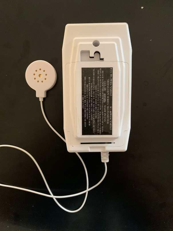
Click to zoom
Application Details
- Equipment Class
- DSC - Part 15 Security/Remote Control Transmitter
- Date of Grant
- Jan 11, 2021
- Application Purpose
- Original Equipment
- Date of Application
- Jan 07, 2021
- Equipment Note
- Medallion Series Transmitter
- Frequency Range
- 418.00000000 - 418.00000000
- Company
- Silent Call Communications
- Country
- United States
Documents & Files
Document Text
Text extracted from the exhibit documents filed with the FCC. Open a document above to read the original.
Users Manual
Installation and Operating Instructions Model CEL-MC Medallion Series Transmitter 1 Document# 109124 Transmitter Features: CEL-MC transmitters are battery operated. CEL-MC is coded at the manufacturer with a unique address ID. Transmitter has a test button for programming and operational testing. When test button is activated the RED LED will illuminate and the CEL-MC will transmit a phone alert to the Silent Call Medallion series receiver. Low Battery YELLOW LED will flash every 10 seconds when batteries are in need of replacement. Installation: 1. The CEL-MC transmitter will work with standard cell phones with the “vibration” alert mode activated, as the cell transmitter will pick up the vibration of your phone. 2. To install the CEL-MC Cell transmitter on a cell phone, find a hard surface, that will not get bumped, that’s in a quiet place to cut down on false signals. Turn On the Cell transmitter and prop the edge of the cell phone on the disk (see photo below). You can also lay the disk on the screen of the cell phone. Test both ways with your cell phone to see which one works better for your type of phone. When the cell phone vibrates, indicating an incoming alert, the disk will feel the vibration of the phone and send a signal to your Medallion receiver. If it doesn’t work, go to Settings on your phone and choose a different vibration pattern. 3. Keep in mind the cell phone transmitter can give false signals if being used on a table, or other surface, that you are using, ie..bumping the table can cause the cell phone transmitter to activate. Also, a very loud noise that causes a vibration can activate the cell transmitter. So, using a surface that is out of the way of being bumped is a good idea. Operation: 1. Whenever the cell phone receives an incoming alert, the Red light on the cell transmitter will light up and the transmitter will send a signal to your Silent Call Medallion Series Receiver causing the receiver to activate “Phone Alert”. Replacement Batteries: Use two AA 1.5V Alkaline Batteries. AA Batteries may be purchased from local retail stores. Transmitter is shipped with 2 AA Alkaline Batteries. Regulatory Information Notice: This device complies with Industry Canada license-exempt RSS standard(s). Operation is subject to the following two conditions: (1) This device may not cause harmful interference, and (2) this device must accept any interference received, including interference that may cause undesired operation of the device. This equipment has been tested and found to comply with the limits for a Class B digital device, pursuant to Part 15 of FCC Rules. These limits are designed to provide reasonable protection against harmful interference in a residential installation. This equipment generates, uses and can radiate radio frequency energy and if not installed and used in accordance with the instructions, may cause harmful interference to radio communications. However, there is no guarantee that interference will not occur in a particular installation. If this equipment does cause harmful interference to radio or television reception, which can be determined by turning the equipment off and on, the user is encouraged to try to correct the interference by one or more of the following measures: • Reorient or relocate the receiving antenna. • Increase the separation between the equipment and the receiver • Connect the equipment into an outlet on a circuit different from that to which the receiver is connected. • Consult the dealer or an experienced radio/television technician for help Unauthorized changes or modifications could void the user’s authority to operate the equipment. Installation and Operating Instructions Model CEL-MC Medallion Series Transmitter 2 Document# 109124 Instructions d’installation et de fonctionnement Français Émetteur de 418MHz RF transmetteur téléphonique Caractéristiques de l’émetteur: Les émetteurs CEL-MC fonctionnent sur piles. CEL-MC est codé chez le fabricant avec un identifiant d'adresse unique. L'émetteur dispose d'un bouton de test pour la programmation et les tests opérationnels. Lorsque le bouton de test est activé, la LED ROUGE s'allume et le CEL-MC transmet une alerte téléphonique au récepteur de la série Silent Call Medallion. La LED JAUNE de batterie faible clignote toutes les 10 secondes lorsque les batteries doivent être remplacées. Installation: 1. L'émetteur CEL-MC fonctionnera avec les téléphones portables standard avec le mode d'alerte «vibration» activé, car l'émetteur cellulaire captera les vibrations de votre téléphone. 2. Pour installer l’émetteur CEL-MC Cell sur un téléphone portable, recherchez une surface dure, qui ne sera pas heurtée, qui est dans un endroit calme pour réduire les faux signaux. Allumez l'émetteur cellulaire et maintenez le bord du téléphone portable sur le disque (voir photo ci- dessous). Vous pouvez également poser le disque sur l'écran du téléphone portable. Testez les deux méthodes avec votre téléphone portable pour voir lequel fonctionne le mieux pour votre type de téléphone. Lorsque le téléphone portable vibre, indiquant une alerte entrante, le disque ressent la vibration du téléphone et envoie un signal à votre récepteur Medallion. Si cela ne fonctionne pas, accédez aux paramètres de votre téléphone et choisissez un autre modèle de vibration. 3. Gardez à l'esprit que l'émetteur du téléphone portable peut donner de faux signaux s'il est utilisé sur une table, ou une autre surface, que vous utilisez, c'est-à-dire que le fait de cogner la table peut provoquer l'activation de l'émetteur du téléphone portable. De plus, un bruit très fort qui provoque une vibration peut activer l'émetteur cellulaire. Donc, utiliser une surface qui ne peut pas être heurtée est une bonne idée. Opération: 1. Chaque fois que le téléphone (ou visiophone) sonne, le voyant rouge sur le transmetteur téléphonique s'allumera et l'émetteur enverra un signal à votre récepteur silencieux de série médaillon appeler causant le …
Text truncated - open the document above for the full version.
Cover Letter(s)
January 7, 2021 American Certification Body, Inc. 6731 Whittier Avenue Suite C110 McLean, VA 22101 Re: Letter of Agency for FCC Compliance Testing Please be advised that Silent Call Communications authorizes Amber Helm Development L.C. Sister Lakes, MI 49047, to act on our behalf in front of the Federal Communications Commission with respect to all matters relating to certification. We certify that we are not subject to denial of federal benefits, that includes FCC benefits, pursuant to Section 5301 of the Anti-Drug Abuse Act of 1988, 21 U.S.C. 862. Further, no party, as defined in 47 CFR 1.2002 (b), to the application is subject to denial of federal benefits, that includes FCC benefits. Dated this __ 7th _____ day of __January_, 20 21. By: ___ George Elwell___________ (Signature) (Print Name) Title, President, Silent Call Communications Email: [email protected] On behalf of: Silent Call Communications 5095 Williams Lake Road Waterford, MI 48329 USA Telephone: 800-572-5227 Fax: 248-673-7360 5095 Williams Lake Road, Waterford, MI 48329 (800) 572-5227 v/tty (248) 673-7360 fax Email: [email protected] Website: www.silentcall.com January 7, 2021 Attn: Director of Certification Authority to Act as Agent I appoint Amber Helm Development L.C. to act as our agent in the preparation of this application for equipment certification. I certify that submitted documents properly describe the device or system for which equipment certification is sought. I also certify that each unit manufactured, imported or marketed, as defined in Industry Canada's regulations will have affixed to it a label identical to that submitted for approval with this application. We also declare that the information provided to the FCC is true and correct to the best of our knowledge (47 CFR 2.911(d)) and we have been informed of the grantee responsibilities (47 CFR 2.909) with regard to certified equipment. For instances where our authorized agent signs the application for certification on our behalf, I acknowledge that all responsibility for complying with the terms and conditions for Certification, as specified by American Certification Body, still resides with Silent Call Communications 5095 Williams Lake Road Waterford, MI 48329 USA Dated this __ 7th _____ day of __January_, 20 21. By: ________George Elwell______________ (Signature) (Print Name) Title: President, Silent Call Communications Email: [email protected] On behalf of: Silent Call Communications 5095 Williams Lake Road Waterford, MI 48329 USA Telephone: 800-572-5227 Fax: 248-673-7360 5095 Williams Lake Road, Waterford, MI 48329 (800) 572-5227 v/tty (248) 673-7360 fax Email: [email protected] Website: www.silentcall.com
Cover Letter(s)
07/09/2020 FCC ID: PPJSCXMIT13 Request for Confidentiality In accordance with 47 C.F.R. Sections 0.457(d) and 0.459, we, Silent Call Communications Corporation, hereby request confidentiality for the block diagram, schematic, bill of material, and theory of operation presented for certification. In support of the Request for Confidentiality, the following is stated: Enclosed within this application is technical information which we deem to be trade secrets and proprietary. If made public, the information might be used to our disadvantage. To assist in assuring that we receive the full value of our product and protect its competitive posture, we respectfully request this grant of confidentiality. George Elwell, President Silent Call Communications Corporation 5095 Williams Lake Road, Waterford, MI 48329 (800) 572-5227 v/tty, (248) 673-7360 fax Email: [email protected] Website: www.silentcall.com
External Photos
Top Right Side Top Side Left Side Bottom Side Bottom
ID Label/Location Info
Label Location
Internal Photos
Internal Photos PCB Top PCB Bottom
Test Report
Amber Helm Development L.C. 92723 Michigan Hwy-152 Sister Lakes, Michigan 49047 USA Tel: 888-847-8027 2002454TX Issued:December 15, 2020 EMC Test Report regarding USA: CFR Title 47, Part 15.231(Emissions) Canada:IC RSS-210v10/GENv5(Emissions) for CEL-MC Category: Remote Control Transmitter Judgments: 15.231 / RSS-210v10 Compliant Testing Completed: December 15, 2020 TESTING NVLAP LAB CODE 200129-0 Prepared for: Silent Call Communications 5095 Williams Lake Rd., Waterford Michigan 48329 USA Phone: (800) 572-5227, Fax: (248) 673-7360 Contact: George Elwell, [email protected] Data Recorded by:Reviewed by: Gordon Helm, EMC-002401-NEGordon Helm, EMC-002401-NE Prepared by: Date of Issue: December 15, 2020 Dr. Joseph Brunett, EMC-002790-NE A copy of this report will remain on file until January 2031.Page 1 of 20 Date: December 15, 2020Prepared For: Silent Call CommunicationsReport No.: 2002454TX Revision History Rev. No.DateDetailsRevised By r0December 15, 2020Initial Release.J. Brunett Contents Revision History2 Table of Contents2 1 Test Report Scope and Limitations4 1.1 Laboratory Authorization . . . . . . . . . . . . . . . . . . . . . . . . . . . . . . . . . . . . . . . . . . .4 1.2 Report Retention . . . . . . . . . . . . . . . . . . . . . . . . . . . . . . . . . . . . . . . . . . . . . . . .4 1.3 Subcontracted Testing . . . . . . . . . . . . . . . . . . . . . . . . . . . . . . . . . . . . . . . . . . . . .4 1.4 Test Data . . . . . . . . . . . . . . . . . . . . . . . . . . . . . . . . . . . . . . . . . . . . . . . . . . . .4 1.5 Limitation of Results . . . . . . . . . . . . . . . . . . . . . . . . . . . . . . . . . . . . . . . . . . . . . .4 1.6 Copyright . . . . . . . . . . . . . . . . . . . . . . . . . . . . . . . . . . . . . . . . . . . . . . . . . . . .4 1.7 Endorsements . . . . . . . . . . . . . . . . . . . . . . . . . . . . . . . . . . . . . . . . . . . . . . . . . .4 1.8 Test Location . . . . . . . . . . . . . . . . . . . . . . . . . . . . . . . . . . . . . . . . . . . . . . . . . .5 1.9 Traceability and Equipment Used . . . . . . . . . . . . . . . . . . . . . . . . . . . . . . . . . . . . . . .5 2 Test Specifications and Procedures6 2.1 Test Specification and General Procedures . . . . . . . . . . . . . . . . . . . . . . . . . . . . . . . . . .6 3 Configuration and Identification of the Equipment Under Test7 3.1 Description and Declarations . . . . . . . . . . . . . . . . . . . . . . . . . . . . . . . . . . . . . . . . .7 3.1.1EUT Configuration . . . . . . . . . . . . . . . . . . . . . . . . . . . . . . . . . . . . . . . . . . .8 3.1.2Modes of Operation . . . . . . . . . . . . . . . . . . . . . . . . . . . . . . . . . . . . . . . . . .8 3.1.3Variants . . . . . . . . . . . . . . . . . . . . . . . . . . . . . . . . . . . . . . . . . . . . . . . . .9 3.1.4Test Samples . . . . . . . . . . . . . . . . . . . . . . . . . . . . . . . . . . . . . . . . . . . . . .9 3.1.5Functional Exerciser . . . . . . . . . . . . . . . . . . . . . . . . . . . . . . . . . . . . . . . . . .9 3.1.6Modifications Made . . . . . . . . . . . . . . . . . . . . . . . . . . . . . . . . . . . . . . . . . .9 3.1.7Production Intent . . . . . . . . . . . . . . . . . . . . . . . . . . . . . . . . . . . . . . . . . . .9 3.1.8Declared Exemptions and Additional Product Notes . . . . . . . . . . . . . . . . . . . . . . . .9 4 Emissions10 4.1 General Test Procedures . . . . . . . . . . . . . . . . . . . . . . . . . . . . . . . . . . . . . . . . . . . . 10 4.1.1Radiated Test Setup and Procedures . . . . . . . . . . . . . . . . . . . . . . . . . . . . . . . . . 10 4.1.2Conducted Emissions Test Setup and Procedures . . . . . . . . . . . . . . . . . . . . . . . . . . 12 4.1.3Power Supply Variation . . . . . . . . . . . . . . . . . . . . . . . . . . . . . . . . . . . . . . . . 12 4.2 Intentional Emissions . . . . . . . . . . . . . . . . . . . . . . . . . . . . . . . . . . . . . . . . . . . . . . 13 4.2.1Fundamental Emission Pulsed Operation . . . . . . . . . . . . . . . . . . . . . . . . . . . . . . 13 4.2.2Fundamental Emission Bandwidth . . . . . . . . . . . . . . . . . . . . . . . . . . . . . . . . . . 15 4.2.3Fundamental Emission Field Strength . . . . . . . . . . . . . . . . . . . . . . . . . . . . . . . . 17 4.3 Unintentional Emissions . . . . . . . . . . . . . . . . . . . . . . . . . . . . . . . . . . . . . . . . . . . . 18 4.3.1Transmit Chain Spurious Emissions . . . . . . . . . . . . . . . . . . . . . . . . . . . . . . . . . 18 4.3.2General Radiated Spurious . . . . . . . . . . . . . . . . . . . . . . . . . . . . . . . . . . . . . . 19 5 Measurement Uncertainty and Accreditation Documents20 Amber Helm Development L.C., 92723 Michigan Hwy-152, Sister Lakes, Michigan 49047 USAPage 2 of 20 Date: December 15, 2020Prepared For: Silent Call CommunicationsReport No.: 2002454TX List of Tables 1Test Site List. . . . . . . . . . . . . . . . . . . . . . . . . . . . . . . . . . . . . . . . . . . . . . . . . . .5 2Equipment List. . . . . . . . . . . . . . . . . . . . . . . . . . . . . . . . . . . . . . . . . . . . . . . . .5 3EUT Declarations. . . . . . . . . . . . . . . . . . . . . . . . . . . . . . . . . . . . . . . . . . . . . . . .8 4Fundamental Emission Pulsed Operation. . . . . . . . . . . . . . . . . . . . . . . . . . . . . . . . . . . 13 5Fundamental Emission Bandwidth.. . . . . . . . . . . . . . . . . . . . . . . . . . . . . . . . . . . . . 15 6Fundamental Emission Field Strength.. . . . . . . . . . . . . . . . . . . . . . . . . . . . . . . . . . . 17 7Transmit Chain Spurious Emissions. . . . . . . . . . . . . . . . . . . . . . . . . . . . . . . . . . . . . . 18 8Radiated Digital Spurious Emissions.. . . . . . . . . . . . . . . . . . . . . . . . . . . . . . . . . . . . 19 9Measurement Uncertainty. . . . . . . . . . . . . . . . . . . . . . . . . . . . . . . . . . . . . . . . . . . . 20 List of Figures 1Photos of EUT.. . . . . . . . . . . . . . . . . . . . . . . . . . . . . . . . . . . . . . . . . . . . . . . .7 2EUT Test Conf…
Text truncated - open the document above for the full version.
Contact Information
Applicant
George Elwell(President)
Test Firm
AHD (Amber Helm Development, L.C.)Gordon Helm
Technical Specifications
| # | Rule Parts | Frequency Range | Power Output |
|---|---|---|---|
| 1 | 15.231(e) | 418 MHz - 418 MHz | - |