PPS-DL-5801C24Cable Access Radio CPE
Wireless Bypass Inc.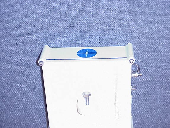
Click to zoom
Application Details
- Equipment Class
- NII - Unlicensed National Information Infrastructure TX
- Date of Grant
- Mar 05, 2002
- Application Purpose
- Original Equipment
- Date of Application
- Mar 05, 2002
- Equipment Note
- Cable Access Radio CPE
- Frequency Range
- 5727.25000000 - 5740.00000000
- Company
- Wireless Bypass Inc.
- Country
- United States
Documents & Files
Document Text
Text extracted from the exhibit documents filed with the FCC. Open a document above to read the original.
Users Manual
PRELIMINARY PRELIMINARY Wireless Bypass DL-5800 5.8 GHz U-NII Wireless CABLE ACCESS SYSTEM Technical & Installation Manual O P E R A T I O N I N S T A L L A T I O N PRELIMINARY PRELIMINARY Proprietary Notice This information and design disclosed herein was originated by and is the property of Wireless Bypass, Inc. Wireless Bypass reserves all patent proprietary design, manufacturing, reproduction use, and sales rights thereto, and to any article disclosed therein, except to the extent rights are expressly granted to others. The foregoing does not apply to vendor proprietary parts. Specifications are typical and subject to change without notice, in order to allow the introduction of design improvements. Wireless Bypass has carefully reviewed the information herein and it is believed to be accurate and reliable. However, no responsibility is assumed for inaccuracies or errors. Use of this information and/or any of our products does not convey to the user any patent rights or licenses. Wireless Bypass reserves the right to change any specifications or information contained herein without notice. Wireless Bypass products are not to be used in life support applications without the expressed written consent of Wireless Bypass. Wireless Bypass 43 Northwestern Drive Salem, N.H. 03079 USA www.wireless-bypass.com Worldwide Sales & Service: TEL: 603-870-6222 FAX 603-870-6279 Copyrighted (c) 2000 Wireless Bypass Salem N.H. 03079 Printed in the U.S.A. PRELIMINARY PRELIMINARY Safety Precautions RF Energy Radiation Warning The radio equipment described in this guide uses radio frequency transmitters. Although the power level is low, the concentrated energy from a directional antenna may pose a health hazard operated incorrectly. All devices must be installed by qualified installation / deployment personnel, and a minimum of 1.5 meters of separation must exist between the device and persons, when the device is operating. The device installers and operators should be aware of the transmitter operating conditions specified in the Wireless Bypass DL-5800 installation manual and other associated user documentation, as well as the antenna co-location requirements of Part 1.1307 (b) (3), of FCC rules, pertaining to RF exposure. Protection from Lightning Article 810 of the US National Electric Department of Energy Handbook 1996 specifies that radio and television lead-in cables must have adequate surge protection at or near the point of entry to the building. The code specifies that any shielded cable from an external antenna must have the shield directly connected to a 10 AWG wire that connects to the building ground electrode. Regulatory Notices: Canada: Operation is subject to the following two conditions: (1) this device may not cause interference, and (2) this device must accept any interference, including interference that may cause undesirable operation of the device. To reduce potential radio interference to other users, the antenna type and its gain should be so chosen that the equivalent isotropic radiated power (EIRP) is not more than that required for successful communication. United States: CAUTION: Modifications to this device not expressly approved by Wireless Bypass may cause the device to exceed regulatory standards and therefore VOID the user’s authority to operate the device. This device complies with Part 15 of the FCC rules. Operation is subject to the following two conditions: (1) this device may not cause PRELIMINARY PRELIMINARY interference, and (2) this device must accept any interference received, including interference that may cause undesirable operation. PRELIMINARY PRELIMINARY System Description Wireless Bypass Cable Access Radio Systems are high performance, wireless, microwave communication links that provide an efficient solution for Cable Modem data transmission requirements. These systems operate in the unlicensed 5.8 GHz U-NII band between 5.725 & 5.825 GHz. The Wireless Bypass DL-5800 Series U-NII Cable Access Radio enables cable operators to expand their cable service market by delivering high-speed Internet service to customers previously inaccessible with the installed HFC network. The Wireless Bypass system described in this manual consists of a HUB radio frequency unit, and a CPE (Customer Premise Equipment) radio frequency unit. Several different antenna configurations may be described for point-to-point, or point-to-multipoint operation. In multipoint configurations, many CPE’s may be used with one HUB. The HUB connects to the installed HFC network using standard cable drop techniques. The HUB contains all the signal processing necessary to transmit the downstream IP data into the coverage area and insert the upstream data bursts into the HFC network. The CPE is a small radio transceiver installed at the customer site that provides the downstream data and a return connection for the customer’s cable modems to the HFC network. The Antenna system used will be determined by the desired coverage area and network topology. Two basic Antenna systems may be used with the DL-5800: Point-to-Point, and Point-to-Multipoint. DL-5800 distance capability will range from about 2 miles in a Point-to- Multipoint implementation, and up to 20 miles for Point-to-Point. Basic main lobe antenna patterns are show below. ***************INSERT ANTENNA PATTERNS HERE*************** Equipment Design Features Wireless Bypass's radio systems provide patent pending advanced designs, incorporating a high level of circuit integration to achieve lower power consumption per terminal, and higher reliability for longer MTBF. Microprocessor-based intelligent monitoring of vital performance functions provides extensive diagnostics that are summarized to provide a single point red LED indicator, which will illuminate in the event of a malfunction. PRELIMINARY PRELIMINARY The highly integrated design of the Wireless Bypass DL-5800 series radio systems provide the user with a cost-efficient radio that is eas…
Text truncated - open the document above for the full version.
Attestation Statements
Wireless Bypass wireless solutions for CMTS and CATV distribution 12/21/2001 Transmitter Mute Switch & Transmitter Frequency Stability To Whom It May Concern: Wireless Bypass has built a transmitter mute function into the U-NII model PPS- DL-5801C24. These mute functions can be traced using the supplied documentation. Specifically, the transmitter mute will take effect from 90% to 10% in less than 1 millisecond in the event of a PLL out of lock, and less than 1 microsecond in the absence of data. Frequency stability of the PPS-DL-5801C24 is controlled by one upconversion at 5.700 GHz. Overall stability over temperature is +/- 1.0 PPM & over time +/- 1.0 PPM yielding a total of +/- 11,400 hz over time and temp. The attached crystal specification is applicable to all cases. Thank you for your help in this matter, David Blumberg, Wireless Bypass 43 Northwestern Drive Salem NH 03079 41 Northwestern Drive, Salem NH 03079 Radio Sales and Support 603-870-6222 603-870-6232 (FAX) www.wireless-bypass.com
Cover Letter(s)
Attention: Application Examiner Reviewing Engineer Re: Request for confidentiality per Section 0.459 of FCC Rules Applicant: Wireless Bypass Inc. FCC ID: PPS-DL-5801C24 To whom it may concern, Request is hereby submitted by Wireless Bypass Inc., to withhold from public review certain portions of the application for equipment certification for the referenced FCC identifiers. In particular, the following sections of the application and report are requested to be kept confidential: • Schematics • Detailed Block diagrams • Detailed Operational/Functional Description Rationale for request for confidentiality: These units must be professionally installed, which does not subject or expose the device to user intrusion. In addition, Wireless Bypass has invested considerable time and materials in research and development to produce the referenced product. Disclosure of the confidential portions of this application to competitors would not only give them competitive advantage in developing similar products, but would also disclose successful implementation of unpublished, leading edge technology developed at Wireless Bypass in the area of microwave diplexers. The fee for confidentiality has been submitted along with the fee for certification. If you have questions or need further information, please contact the undersigned. Sincerely, David Blumberg Wireless Bypass VP & COO 603-870-6220
Cover Letter(s)
MODEL VTXO700 Voltage Controlled Temperature Compensated Crystal Oscillators Low profile surface mountable VCTCXO available in custom frequencies from 8.2MHz to 32MHz with a clipped sinewave output Product Description This Colpitts oscillator uses the direct two−port temperature compensation method. Operating on the fundamental mode, the circular AT−cut crystal is housed in the environmentally rugged UM−1 SLIM resistance weld package. The product can be configured to operate on any voltage between 2.7V and 5V. A mechanical trimmer is available for adjusting the frequency. Customized frequencies readily available make this model suitable for many timing and frequency applications where an HCMOS output is required. Features Compatible with normal solder reflow processes Excellent temperature stability performance Able to operate over industrial temperature ranges Low hysteresis Low power consumption Excellent vibration performance Very good phase noise performance Frequency control ranges from 6 to 50ppm available 1.0SPECIFICATION REFERENCES 1.1Model Description VTXO710R 10.0 MHz 1.2Reference Number 3515 1.3CompanyWireless Bypass 2.0FREQUENCY CHARACTERISTICS LineParameterTest ConditionMin.Max.Units 2.1Nominal Frequency Nominal Frequency referenced to 25 deg. C.10.0MHz 2.2Frequency calibration Frequency at 23 deg. C +/−2 deg. C (see Note 1)1.0+/−ppm 2.3Frequency stability over temperature Referenced to frequency reading at 25 deg. C. Temperature varied at max. of 2 deg. C per minute. Control voltage held at voltage control range midpoint. (Note 2) 1.0+/−ppm 2.4Temperature range The operating temperature range over which the frequency stability is measured (Note 3) −20.0 70.0Degrees C 2.5Frequency perturbations Peak to peak amplitude of frequency perturbation within operating temperature range (Note 1) 0.5ppm 2.6Frequency slopeMinimum of 1 frequency reading every 2 degrees C, over the operating0.5ppm/deg C © 1998 Rakon Limited PG 01 PRODUCT SPECIFICATION of perturbationstemperature range (Note 1) 2.7Static temperature hysteresis Frequency change after reciprocal temperature ramped over the operating range. Frequency measured before and after at 25 deg C 0.4+/−ppm 2.8Supply voltage stability Supply voltage varied +/−5% at 25 deg C. Frequencies above 25MHz are not able to be specified below the max. value given. (Note 1) 0.3+/−ppm 2.9Load sensitivity+/−10% load change0.2+/−ppm 2.10Root Allan Variance 1 second Tau. (Note 1)1.0ppb 2.11Long term stability Frequency drift over 1 year (Note 1)1.0+/−ppm 2.12G SensitivityGamma vector of all three axes from 30Hz to 1500Hz (Note 1)1.0ppb/G 2.13Trimmer adjustment Manual adjustment using trimmer tool3.0+/−ppm 3.0POWER SUPPLY LineParameterTest ConditionMin.Max.Units 3.1Supply voltageSupply voltage range based on nominal 5V4.755.25V 3.2CurrentAt Max. supply voltage2.0mA 4.0CONTROL VOLTAGE LineParameterTest ConditionMin.Max.Units 4.1Control voltage range Determined by supply voltage (Note 5). The nominal control voltage value is midway between the minimum and maximum. 0.54.5V 4.2Frequency tuningFrequency shift from Min. to Max. control voltages (Note 6)6.0ppm 4.3Frequency tuning linearity Deviation from straight line curve fit (Note 1)20.0% 4.4Port input impedance 100.0K Ohms 5.0OSCILLATOR OUTPUT LineParameterTest ConditionMin.Max.Units 5.1Output waveformClipped sinewave 5.2Output voltage level At min. supply voltage1.0V 5.3Output load resistance Operating range18.022.0K Ohms © 1998 Rakon Limited PG 02 PRODUCT SPECIFICATION 5.4Output load capacitance Operating range4.55.5pF 6.0SSB PHASE NOISE LineParameterTest ConditionMin.Max.Units Quiescent measurement at room temperature. Phase noise dependent on oscillator frequency. The dBc/Hz are typical values. 6.1SSB Phase noise density 1Hz offset−70.0dBc/Hz 6.2SSB Phase noise density 10Hz offset−100.0 dBc/Hz 6.3SSB Phase noise density 100Hz offset−130.0 dBc/Hz 6.4SSB Phase noise density 1KHz offset−145.0 dBc/Hz 6.5SSB Phase noise density 10KHz offset−150.0 dBc/Hz 7.0ENVIRONMENTAL The oscillator shall meet electrical characteristics and suffer no physical damage after being subject to the following conditions: 7.1ShockHalf sinewave acceleration of 100G peak amplitude for 11ms duration, 3 cycles each plane. 7.2Random Vibration 10G RMS 30Hz to 1500Hz duration of 6 Hours. 7.3HumidityAfter 48hours at 85 deg C +/−2% deg C 85% relative humidity non−condensing 7.4Thermal shock test Exposed at −40 deg C for 30 minutes then to 85 deg C for 30 minutes constantly for a period of 5 days. 7.5Storage temperature −40 to 85 deg C 8.0MARKING 8.1TypeEngrave 8.2Line 1Rakon logo 8.3Line 2Model descriptive 8.4Line 3Frequency in MHz (to 3 decimal places or greater depending on the no. of significant digits after the decimal point) 8.5Line 4Date code WWYY © 1998 Rakon Limited PG 03 PRODUCT SPECIFICATION 9.0MANUFACTURING INFORMATION 9.1Reflow and washing Able to withstand normal solder reflow processes but not aqueous washing due to presence of trimmer with open dielectric exposure. 9.2Packaging description Tape and reel 10.0SPECIFICATION NOTES 10.1Note 1The Max. value is the specification. A Min. value, if present, indicates the tightest specification available. 10.2Note 2A max. frequency stability over the temperature is required to be specified. For this model, values between to +/−1ppm and +/−10ppm are available. Standard options are +/−1ppm, +/−1.5ppm, +/−2ppm and +/−2.5ppm. 10.3Note 3The operating temperature range needs to be specified. The extremes for this model are −40 and +85 deg C. If either or both ends of the operating temperature range are at these extremes, then the frequency stability options are limited to greater than +/−1.5ppm. 10.4Note 4Standard power supply options are 2.7V, 3V, 3.3V, 4V or 5V, but any value between Min. & Max. is available. 10.5Note 5This range is normally 0.5V to Supply voltage less 0.5V i.e. for a supply voltage of 3V, the range is 0.5V to 2.5V. 10.6Note 6The Min value is the specification. A Max v…
Text truncated - open the document above for the full version.
External Photos
Back Front Bottom Top Left Right
ID Label/Location Info
Label Information FCC ID: PPS-DL-5801C24 IC ID: Canada ___________________ This device comp lies with Part 15 of the FCC Rules. Op eration is subject to the following two conditions: (1) This device may not cause harmful int erferen ce, and (2) t his devi ce must acc ep t any int erference rece ived, in cludin g int erferenc e t hat may cause undesired op eration. M odel # DL-5801C24 Wireless By p ass Salem NH USA VHF MONVHF / PowerSwitch Access –20 dB
Internal Photos
Chassis Bottom Chassis Top PC Board Bottom PC Board Top
Operational Description
FCC Part 15 certification Questions from Roland Gubisch @ ITS Relationship between switch programming and RF power output The RF power switch settings are selected such that the maximum peak power emissions with the selected antenna are not exceeded. The switches define a 6-bit control word that sets the output power. Example: a single channel (6 MHz) hub system has a maximum peak power of 24.78 dBm into a 6 dBi antenna. Using a 15 dBi gain antenna requires a reduction in output power of 9 dB or a maximum output power of 15.78 dBm into the antenna. A control word of 110001 (49 decimal) is selected giving an output power of 15.4 dBm into the 15 dBi antenna. All switch settings for the various antennas are calculated in the same fashion. Point-to-multipoint systems use the maximum antenna gain of 6 dBi and point-to- point systems 23 dBi for the maximum antenna gain Output power vs. Control Word -40 -30 -20 -10 0 10 20 30 0 102030405060 Control Word Output Power (dBm ) Peak Power dBm
RF Exposure Info
Wireless Bypass wireless solutions for CMTS and CATV distribution 41 Northwestern Drive, Salem NH 03079 Radio Sales and Support 603-870-6222 603-870-6232 (FAX) www.wireless-bypass.com Statement of Radiofrequency Radiation Exposure Limits 47 CFR Sec. 1.1310 defines the limits for uncontrolled and controlled exposure. For transmitters operating in the 5725 – 5825 MHz frequency band the exposure limits for uncontrolled and controlled exposures are 5 mW/cm 2 and 1 mW/c m 2 respectively. Wireless Bypass offers two configurations of UNII band radio systems, point-to-multipoint (P/MP) and point-to-point (P/P). Each configuration of radio system contains a ‘downstream unit’ designated with an ‘H’ e.g. DL5800H, and an ‘upstream unit’ designated with a ‘C’. The ‘downstream unit’, DL5800H, has a 26 dB transmitter bandwidth of approximately 6 MHz and the ‘upstream unit’, DL5800C, has a 26 dB transmitter bandwidth of approximately 3.2 MHz. The following table gives give the distance from the antenna that the power density is 1 mW/cm 2 and the power density at a distance of 1.5 meters from the antenna. 1.5 meters is required in the Users Manual for uncontrolled distance. Radio SystemMaximum Peak EIRP (dBm) Distance for 1 mW/cm 2 (cm) Power Density at 1.5 meter (mw/cm 2 ) DL5800H P/MP31.789.760.0042 DL5800H P/P48.7869.090.2121 DL5800C P/MP28.057.130.0023 DL5800C P/P45.0550.450.1131 The following is the relevant text from the DL5800 Technical Manual RF Exposure Limits The DL5800 series transceivers and associated antenna shall be installed by qualified personal. Section 1.1310 of the Federal Communication Commission Regulations sets limits on the field strengths and power densities allowable for human exposure. To comply with Radiofrequency exposure requirements, the antennas used for the DL5800 series shall be installed to provide a minimum distance of 1.5 meters where persons may have access. Antenna Warning A label or sign containing the following language shall be placed on or near the antenna and visible from at least 1.5 meters: CAUTION: To comply with RF exposure require ments, this antenna must be installed to provide a separation distance of at least 1.5 meters from all persons .
Test Report
Intertek Testing Services 70 Codman Hill Road, Boxborough, MA, 01719 Wireless Bypass, FCC ID: PPS-DL-5801C24Date of Test: June 11 -- 19, November 28-29, 2001 Report # 3015156FCC Part 15.407 Certification ii Table of Contents 1.0Summary of Tests..................................................................................................................1 2.0General Description...............................................................................................................2 2.1Product Description..................................................................................................2 2.2Related Submittal(s) Grants.......................................................................................2 2.3Test Methodology.....................................................................................................3 2.4Test Facility..............................................................................................................3 3.0System Test Configuration....................................................................................................3 3.1Support Equipment and description...........................................................................4 3.2Block Diagram of Test Setup.....................................................................................5 3.3Justification...................................................................................................6 3.4Software Exercise Program.......................................................................................6 3.5Mode of operation during test....................................................................................6 3.6Modifications required for Compliance......................................................................6 3.7Additions, deviations and exclusions from standards...................................................6 4.0Measurement Results............................................................................................................7 4.1Conducted Output Power at Antenna Terminal..........................................................7 4.226 dB Bandwidth......................................................................................................8 4.3Power Density..........................................................................................................9 4.4The ratio of the peak excursion of the modulation envelope to the peak power..........10 4.5Out of Band Emissions............................................................................................11 4.6Transmitter Radiated Emissions in Restricted Bands.................................................18 4.8AC Line Conducted Emission..................................................................................19 4.8.1Line Conducted Emission Limits..................................................................19 4.9Radiated Emissions from Digital Section...................................................................21 4.10Radiated Emissions from Receiver Section...............................................................22 4.11Transmitter Duty Cycle Calculation / Measurements.................................................23 4.12Frequency Stability...................................................................................................24 5.0List of Test Equipment.........................................................................................................25 Intertek Testing Services 70 Codman Hill Road, Boxborough, MA, 01719 Wireless Bypass, FCC ID: PPS-DL-5801C24Date of Test: June 11 -- 19, November 28-29, 2001 Report # 3015156FCC Part 15.407 Certification 1 1.0Summary of Tests Wireless Bypass, Model: DL-5801C24 FCC ID: PPS-DL-5801C24 TESTREFERENCERESULTS Output power15.407 (a)Pass 26 dB Bandwidth*15.407 (a)For calculation only Power Density15.407 (a) (5)Pass The ratio of the peak excursion of the modulation envelope to the peak transmit power 15.407 (a) (6)Pass Out of Band Antenna Conducted Emission15.407 (b)Pass Radiated Emission in Restricted Bands15.205Pass AC Conducted Emission15.207Pass Radiated Emission from Digital Module15.209Pass Radiated Emission from Receiver15.209Pass Radiation Exposure Requirement1.1310Pass Frequency Stability15.407(g)Pass Antenna Requirement15.203Pass, Professional Install Test Engineer: Date: Nicholas Abbondante Staff Engineer: Date: Michael F. Murphy Intertek Testing Services 70 Codman Hill Road, Boxborough, MA, 01719 Wireless Bypass, FCC ID: PPS-DL-5801C24Date of Test: June 11 -- 19, November 28-29, 2001 Report # 3015156FCC Part 15.407 Certification 2 2.0General Description 2.1Product Description The EUT Model No.: DL-5801C24 is an intentional transmitter used for wireless point-to-point and point-to- multipoint communications operating in the frequency range: 5.725-5.825 GHz. A pre-production version of the sample was received on June 11, 2001 and on November 28, 2001 in good condition. Overview of the Cable Access Radio CPE Applicant Wireless Bypass, Inc. Trade Name & Model No.Cable Access Radio CPE, Model: DL-5801C24 FCC IdentifierPPS-DL-5801C24 Use of ProductPoint-to-point fixed and point-to-multipoint wireless interconnect Type of Transmission256 QAM, 64 QAM Maximum RF Output (dBm) *10.97 dBm Frequency Range (MHz)5.725 – 5.825 GHz Number of Channel(s)3 Antenna(s) & Gain, dBiPoint-to-Point: Flat Panel Antenna, 23 dBi Parabolic Antenna, 28, 34.6, and 37.6 dBi Point-to-Multipoint: Flat Panel Antenna, 12, 15, 16, 18 and 23 dBi Antenna Requirement[ ]The EUT uses a permanently connected antenna. [ ]The antenna is affixed to the EUT using a unique connector which allows for replacement of a broken antenna, but DOES NOT use a standard antenna jack or electrical connector. [ x ]The EUT requires professional installation (attach supporting documentation if using this option). Manufacturer name & addressWireless Bypass, Inc. 43 Northwestern Drive Salem, MA, 030…
Text truncated - open the document above for the full version.
Test Setup Photos
Configuration Photograph 2’ Parabolic Point-to-Point 28 dBi Gain Configuration Photograph (Continued) 6’ Parabolic Point-to-Point 37.6 dBi Gain Configuration Photograph (Continued) Flat Panel Point-to-Point 23 dBi Gain Configuration Photograph (Continued) Flat Panel Point-to-Multipoint 23 dBi Gain Configuration Photograph (Continued) Flat Panel Point-to-Multipoint 12dBi Gain Configuration Photograph Line-conducted emissions, CPE
Contact Information
Applicant
David Blumberg(VP & COO)
Technical Contact
Intertek Testing ServicesNicholas Abbondante
[email protected]978 263 2662
70 Codman Hill Road · Boxborough, Massachusetts · United States
Non-Technical Contact
Intertek Testing ServicesNicholas Abbondante
[email protected]978-263-2662
Test Firm
Intertek Testing Services NA Inc.Roland Gubisch
Technical Specifications
| # | Rule Parts | Frequency Range | Power Output |
|---|---|---|---|
| 1 | 15E | 5.73 GHz - 5.74 GHz | 12.50 mW |
Other Applications from Wireless Bypass Inc.

PPS-DL-5800C24
Aug 31, 2001Cable Access Radio CPE
Equipment Class
NII - Unlicensed National Information Infrastructure TX
PPS-DL-5800H24
Aug 31, 2001Cable Access Radio Hub
Equipment Class
NII - Unlicensed National Information Infrastructure TX