PRV-CF-2002Compact Flash Wireless LAN Card
yLez Technologies Pte Ltd.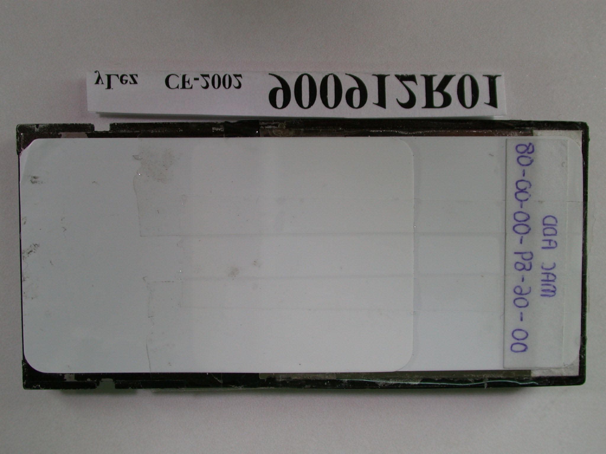
Click to zoom
Application Details
- Equipment Class
- DTS - Digital Transmission System
- Date of Grant
- Sep 20, 2001
- Application Purpose
- Original Equipment
- Date of Application
- Sep 20, 2001
- Equipment Note
- Compact Flash Wireless LAN Card
- Frequency Range
- 2412.00000000 - 2462.00000000
- Company
- yLez Technologies Pte Ltd.
- Country
- Singapore
Documents & Files
Document Text
Text extracted from the exhibit documents filed with the FCC. Open a document above to read the original.
Users Manual
yLez CF-2002 Compact Flash Wireless Network Interface Card Product Manual Revision 1 September 2001 yLez Technologies Pte Ltd No part of this document may be reproduced or transmitted in any means, electronic or mechanical, for any purpose, without the written permission of yLez Technologies Pte Ltd. Information in this document is subject to change without notice. yLez Technologies Pte Ltd makes no representation or warranties with respect to the contents of this manual and specifically disclaims any express or implied warranties of merchantability or fitness for any particular purpose. @ yLez Technologies Pte Ltd All rights reserved. CF-2002 TM and yLez Technologies are trademarks of yLez Technologies Pte Ltd Other trademarks used are properties of their respective owners. Printed in Singapore. DOC-CF-2002-USERMANUAL-RELEASE_1.0 Table of Contents i Table of Contents Chapter 1 Introduction.....................................................................................................1 1.1 CF-2002 Compact Flash WLAN Adapter................................................................2 Chapter 2 Overview of IEEE 802.11 Wireless LAN Technology.........................4 2.1 Introduction to Wireless LAN.................................................................................4 2.2 IEEE 802.11b High Data Rate (HR) Standard.........................................................5 2.3 Frequency Channels...............................................................................................5 2.4 Scanning, Beaconing & ESSID...............................................................................5 2.5 The Benefits of Wireless LANs..............................................................................7 2.6 Designing and building a Wireless LAN System..................................................8 2.7 WLAN Configuration.............................................................................................11 2.7.1 Adhoc (Peer-to-Peer) Network.......................................................................11 2.7.2 Infrastructure Network...................................................................................12 2.8 Wireless LAN Security.......................................................................................13 Chapter 3 Installing and Configuring the Driver in Windows CE....................14 3.1 Installing the CF-2002 Windows CE Driver and Application Program.........14 3.2 Configuring the CF-2002 Windows CE Driver and Application Program.....15 3.3 Driver and Application Un-installation for Windows CE...............................18 Chapter 4 WLAN Connection Monitoring Application......................................19 Chapter 5 Technical Specifications of CF-2002...............................................20 Chapter 6 Channels............................................................................................22 Chapter 7 Technical Support.............................................................................23 Introduction Page 1 Chapter 1 Introduction Welcome to the yLez Technologies CF-2002 User Manual. This manual covers the installation, control, and maintenance of your CF-2002 Compact Flash Wireless Network Interface Adapter. The package you have received should contain the following items: • CF-2002 Compact Flash Wireless Network Interface Card • Compact Disc (CD) containing CF-2002 WLAN Configuration Application and drivers Note: If anything is missing, please contact your vendor. The CD contains both the drivers and Configuration Application. The WLAN Configuration Application is used to manage the CF-2002 Compact Flash Wireless Network Interface Adapter. The CF-2002 drivers are used to setup the CF-2002 Compact Flash Wireless Network Interface Adapter on Windows CE 3.0 platforms. Introduction Page 2 1.1 CF-2002 Compact Flash WLAN Adapter This chapter provides the information on the CF-2002 Compact Flash WLAN Adapter, along with an overview of Wireless Local Area Network (WLAN), including Adhoc (pear-to- pear) and Infrastructure networks. In addition, information is also provided on spread spectrum technology, and security. With the yLez CF-2002 Compact Flash WLAN Card, you can connect the PDAs and handheld devices to the 802.11b wireless LANs. It provides a high-speed and cable-free communication to PDA device mobile users. The CF-2002 is designed for PDA devices with CF Type I/II extended card slots. Powered with Intersil PRISM II.V chipset, the CF-2002 fully supports the Microsoft Windows for Pocket PC. Designed for interoperability, the CF-2002 is designed to the latest IEEE 802.11b High Rate (HR) standard. The CF-2002 is used with any IEEE 802.11b compliant Access Points to connect a mobile device to an existing wired Ethernet LAN infrastructure. Simply speaking, the CF-2002 provides a transparent wireless connection to a wired network. A high-performance spread spectrum transceiver delivers robust and error-free communications at a maximum data rate of 11 Mbps. The CF-2002 has an automatic backoff capability to 5.5 Mbps, 2 Mbps, or 1 Mbps if necessary as specified by the IEEE 802.11b High Rate (HR) standard. The Cf-2002 supports the Windows CE 3.0 for Pocket PC, and even the latest Microsoft Merlin OS for Pocket PC. The CF-2002 comes with the following main features: • CompactFlash form factor, designed specially for handheld and PDA devices with CF Type I/II extended card slots • Fully support Microsoft Windows CE 3.0 Pocket PC and Merlin OS • Compliant to IEEE 802.11b High Data Rate wireless LAN standard. • Indoor range of 120 ft (37 M) in a typical office environment, 400 ft • Outdoor range of 400 ft (100 M) line of sight • Automatic Rate scaling at 11, 5.5, 2, and 1 Mbps data transfer rate for maximum range Introduction Page 3 • WEP security with 40 bit or 128 bit encryption • Advanced power management for low power consumption • Fully compatibility with the Pocket PC and handheld device…
Text truncated - open the document above for the full version.
External Photos
Page 1 ANNEX PHOTOGRAPHS OF EUT Page 2
ID Label/Location Info
FCC ID Location
ID Label/Location Info
Operation is subject to Following Two conditions: (2) This device must accept any interference received, This unit complies with Part 15 of FCC Rules (1) This device may not cause Harmful Interference Including interference that may cause undesired operation Made In Singapore FCC ID: PRV-CF - 2002 Compact Flash Wireless LAN Card CF CF CF CF - -- - 2002 2002 2002 2002 yLez • IEEE 802.11b Compliant • DSSS at 2.4GHz ISM Band
Internal Photos
Page 3 Page 4
RF Exposure Info
FCC ID: PRV-CF-2002 ADT No.: 900912R01 FCC TEST REPORT REPORT NO.: RF900912R01 MODEL NO.: CF-2002 ACCORDING: FCC Guidelines for Human Exposure IEEE C95.1 APPLICANT:yLez Technologies Pte Ltd. ADDRESS: No.1, Tannery Road, #09-03 Cencon 1, Singapore 347719 ISSUED BY:Advance Data Technology Corporation LAB LOCATION:47 14th Lin, Chiapau Tsun, Linko, Taipei, Taiwan, R.O.C. 0528 Lab Code: 200102-0 FCC ID: PRV-CF-2002 ADT No.: 900912R01 RF Exposure Measurement (Mobile Device) 1. Introduction 2.4 GHz frequency band is regarded specially as a dangerous band for its heating harmfulness to the human body. That’s why microwave oven is operating in this frequency band. The manufacturer whose product is working in this frequency band is obligatory to prove the harmfulness of his product. In this document, we try to prove the safety of radiation harmfulness to the human body for our product. The limit for Maximum Permissible Exposure (MPE) specified in FCC 1.1310 is followed. The Gain of the antenna used in this product is measured in a Fully Anechoic Chamber (FAC), and the maximum total power input to the antenna is measured. Through the Friis transmission formula and the maximum gain of the antenna, we can calculate the distance, away from the product, where the limit of MPE is reached. 2. Classification The antenna of the product, under normal use condition, is at least 20 cm away from the body of the user. Warning statement for keeping 20 cm separation distance and the prohibition of operating next to a person has been printed on the users manual. So, this product is classified as the Mobile Device. 3. RF Exposure Limit According to FCC 1.1310: The criteria listed in the following table shall be used to evaluate the environmental impact of human exposure to radio-frequency (RF) radiation as specified in 1.1307(b). FCC ID: PRV-CF-2002 ADT No.: 900912R01 LIMITS FOR MAXIMUM PERMISSIBLE EXPOSURE (MPE) Frequency Range (MHz) Electric Field Strength (V/m) Magnetic Field Strength (A/m) Power Density (mW/cm 2 ) Average Time (minutes) (A)Limits For Occupational / Control Exposures 30-30061.40.1631.06 300-1500......F/3006 1500-100,000......56 (B)Limits For General Population / Uncontrolled Exposure 30-30027.50.0730.230 300-1500......F/150030 1500-100,000......1.030 F = Frequency in MHz 4. Friis Formula Friis transmission formula : Pd = (Pout*G) / (4*pi*r 2 ) where Pd = power density in mW/cm 2 Pout = output power to antenna in mW G = gain of antenna in linear scale Pi = 3.1416 R = distance between observation point and center of the radiator in cm Pd is the limit of MPE, 1 mW/cm 2 . If we know the maximum Gain of the antenna and the total power input to the antenna, through the calculation, we will know the distance r where the MPE limit is reached. Ref. : David K. Cheng, Field and Wave Electromagnetics, Second Edition, Page 640, Eq. (11-133). 5. EUT Operating condition The software provided by Manufacturer enabled the EUT to transmit and receive data at lowest, middle and highest channel individually. FCC ID: PRV-CF-2002 ADT No.: 900912R01 6. Test Results 6.1 Antenna Gain The maximum Gain measured in Fully Anechoic Chamber is -1dBi or 0.79 (numeric). 6.2 Output Power Into Antenna & RF Exposure Distance : CHANNEL CHANNEL FREQUENCY (MHz) OUTPUT POWER TO ANTENNA (mW) MINIMUM ALLOWABLE DISTANCE ( r ) FROM SKIN (Centi-Meter) 1241263.241.99 6243754.331.85 11246251.521.80 The minimum allowable distance is very close to the enclosure of the antenna and is very far away from the human being under normal use condition.
Test Report
FCC ID: PRV-CF-2002 Report No.: RF900912R01 1 Issued: September 20, 2001 FCC TEST REPORT REPORT NO.: RF900912R01 MODEL NO.: CF-2002 RECEIVED: September 12, 2001 TESTED: Sep. 13~ Sep. 15, 2001 APPLICANT: yLez Technologies Pte Ltd. ADDRESS: No.1, Tannery Road, #09-03 Cencon 1, Singapore 347719 ISSUED BY: Advance Data Technology Corporation LAB LOCATION: 47 14th Lin, Chiapau Tsun, Linko, Taipei, Taiwan, R.O.C. This test report consists of 49 pages in total. It may be duplicated completely for legal use with the approval of the applicant. It should not be reproduced except in full, without the written approval of our laboratory. The client should not use it to claim product endorsement by CNLA, NVLAP or any government agencies. The test results in the report only apply to the tested sample. 0528 Lab Code: 200102-0 FCC ID: PRV-CF-2002 Report No.: RF900912R01 2 Issued: September 20, 2001 Table of Contents 1CERTIFICATION ........................................................................................... 4 2SUMMARY OF TEST RESULTS ................................................................... 5 3GENERAL INFORMATION............................................................................ 6 3.1GENERAL DESCRIPTION OF EUT.............................................................. 6 3.2DESCRIPTION OF TEST MODES ................................................................ 7 3.3GENERAL DESCRIPTION OF APPLIED STANDARDS ............................... 7 3.4DESCRIPTION OF SUPPORT UNITS .......................................................... 8 4TEST TYPES AND RESULTS ....................................................................... 9 4.1CONDUCTED EMISSION MEASUREMENT ................................................ 9 4.1.1LIMITS OF CONDUCTED EMISSION MEASUREMENT .............................. 9 4.1.2TEST INSTRUMENTS................................................................................... 9 4.1.3TEST PROCEDURES ................................................................................. 10 4.1.4TEST SETUP .............................................................................................. 10 4.1.5EUT OPERATING CONDITIONS ................................................................ 11 4.1.6TEST RESULTS .......................................................................................... 12 4.2RADIATED EMISSION MEASUREMENT ................................................... 18 4.2.1LIMITS OF RADIATED EMISSION MEASUREMENT ................................. 18 4.2.2TEST INSTRUMENTS................................................................................. 19 4.2.3TEST PROCEDURES ................................................................................. 20 4.2.4TEST SETUP .............................................................................................. 21 4.2.5EUT OPERATING CONDITIONS ................................................................ 21 4.2.6TEST RESULTS .......................................................................................... 22 4.36DB BANDWIDTH MEASUREMENT .......................................................... 27 4.3.1LIMITS OF 6dB BANDWIDTH MEASUREMENT ........................................ 27 4.3.2TEST INSTRUMENTS................................................................................. 27 4.3.3TEST PROCEDURE.................................................................................... 28 4.3.4TEST SETUP .............................................................................................. 28 4.3.5EUT OPERATING CONDITIONS ................................................................ 28 4.3.6TEST RESULTS .......................................................................................... 29 4.4MAXIMUM PEAK OUTPUT POWER .......................................................... 33 4.4.1LIMITS OF MAXIMUM PEAK OUTPUT POWER MEASUREMENT ........... 33 4.4.2TEST INSTRUMENTS................................................................................. 33 4.4.3TEST PROCEDURES ................................................................................. 34 4.4.4TEST SETUP .............................................................................................. 34 4.4.5EUT OPERATING CONDITIONS ................................................................ 34 FCC ID: PRV-CF-2002 Report No.: RF900912R01 3 Issued: September 20, 2001 4.4.6TEST RESULTS .......................................................................................... 35 4.5POWER SPECTRAL DENSITY MEASUREMENT ...................................... 36 4.5.1LIMITS OF POWER SPECTRAL DENSITY MEASUREMENT ................... 36 4.5.2TEST INSTRUMENTS................................................................................. 36 4.5.3TEST PROCEDURE.................................................................................... 37 4.5.4TEST SETUP .............................................................................................. 37 4.5.5EUT OPERATING CONDITIONS ................................................................ 37 4.5.6TEST RESULTS .......................................................................................... 38 4.6BAND EDGES MEASUREMENT ................................................................ 42 4.6.1LIMITS OF BAND EDGES MEASUREMENT .............................................. 42 4.6.2TEST INSTRUMENTS................................................................................. 42 4.6.3TEST PROCEDURE.................................................................................... 42 4.6.4EUT OPERATING CONDITION .................................................................. 43 4.6.5TEST RESULTS .......................................................................................... 43 4.7ANTENNA REQUIREMENT ........................................................................ 46 4.7.1STANDARD APPLICABLE .................…
Text truncated - open the document above for the full version.
Test Setup Photos
FCC ID: PRV-CF-2002 Report No.: RF900912R01 47 Issued: September 20, 2001 5 PHOTOGRAPHS OF THE TEST CONFIGURATION CONDUCTED EMISSION TEST FCC ID: PRV-CF-2002 Report No.: RF900912R01 48 Issued: September 20, 2001 RADIATED EMISSION TEST
Contact Information
Applicant
Lim Boon Lum(V.P. (R&D))
Technical Contact
Advance Data Technology CorporationAlan Lane
[email protected]+886 3 327 0910
13-1, Lane 19, WenShan 3rd St · Taoyuan · Taiwan
Test Firm
Bureau Veritas CPS (H.K.) Ltd. Taoyuan BranchRichard Chen
Technical Specifications
| # | Rule Parts | Frequency Range | Power Output |
|---|---|---|---|
| 1 | 15C | 2.41 GHz - 2.46 GHz | 63.00 mW |
Other Applications from yLez Technologies Pte Ltd.
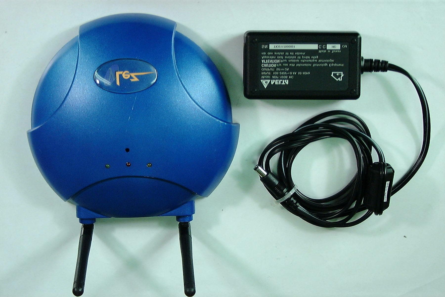
PRV-AP-830
Jul 19, 2001Wireless LAN Access Point
Equipment Class
DSS - Part 15 Spread Spectrum Transmitter