PRWFT901
World Symbol Ltd.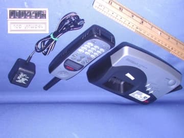
Click to zoom
Application Details
- Equipment Class
- DSS - Part 15 Spread Spectrum Transmitter
- Date of Grant
- Jan 27, 2002
- Application Purpose
- Original Equipment
- Date of Application
- Aug 19, 2001
- Frequency Range
- 903.93600000 - 926.20800000
- Company
- World Symbol Ltd.
- Country
- Hong Kong
Documents & Files
Document Text
Text extracted from the exhibit documents filed with the FCC. Open a document above to read the original.
External Photos
External photos FCC ID: PRWFT901 External photos FCC ID: PRWFT901
Internal Photos
Internal photosFCC ID: PRWFT901 Base assembly Base Main PCB comp s ide Internal photosFCC ID: PRWFT901 Base Main PCB solder side Base Oscillator PCB co mp side Internal photosFCC ID: PRWFT901 Base Oscillator PCB so lde r side LED display comp side Internal photosFCC ID: PRWFT901 LED display solder side Internal photosFCC ID: PRWFT901 Ha ndse t asse mbly Ha ndse t Main PCB co mp s ide Internal photosFCC ID: PRWFT901 Handset Main PCB display side Ha ndse t Oscillato r PCB co mp s ide Internal photosFCC ID: PRWFT901 Ha ndse t Oscillato r PCB solde r side
RF Exposure Info
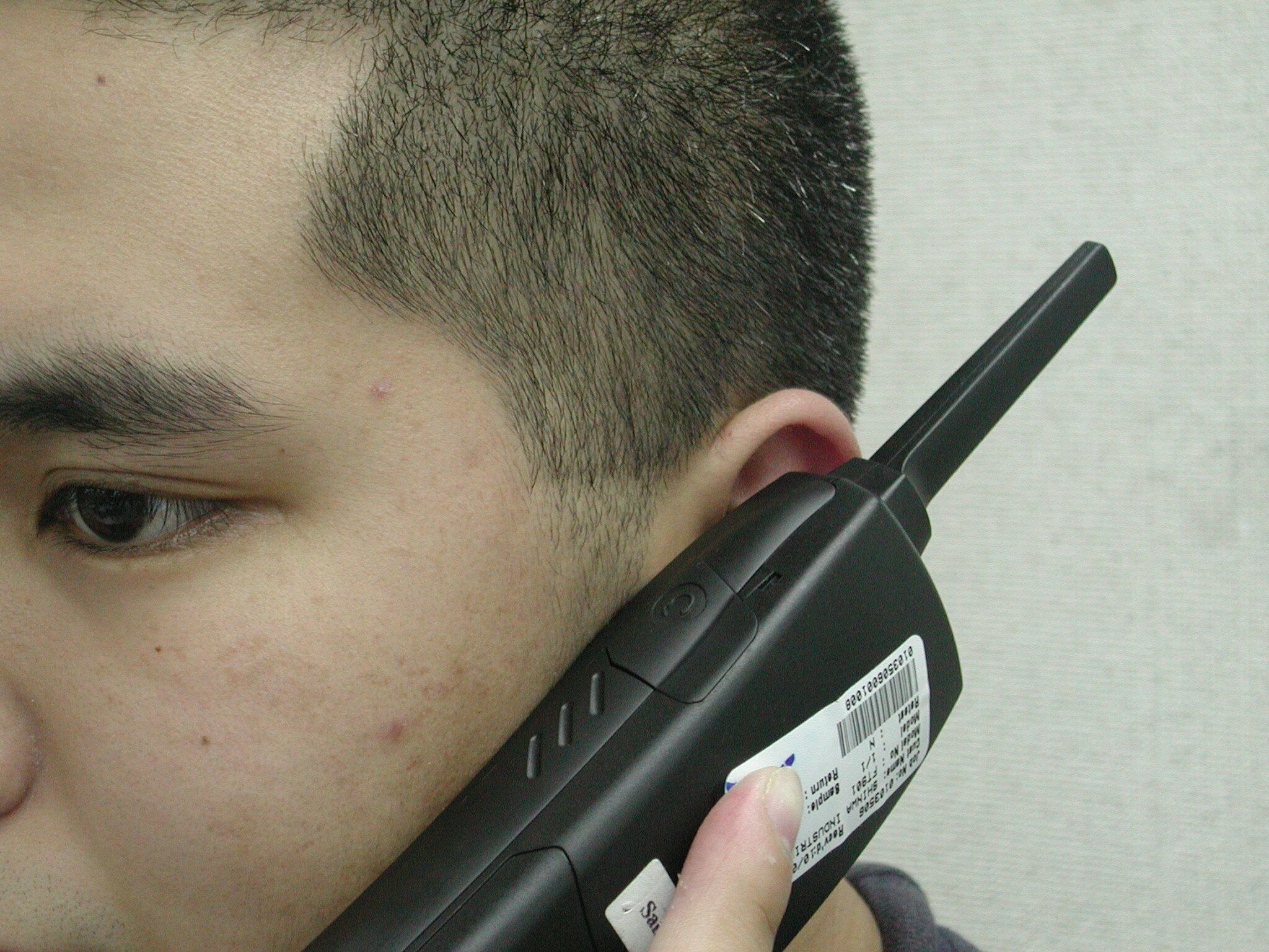
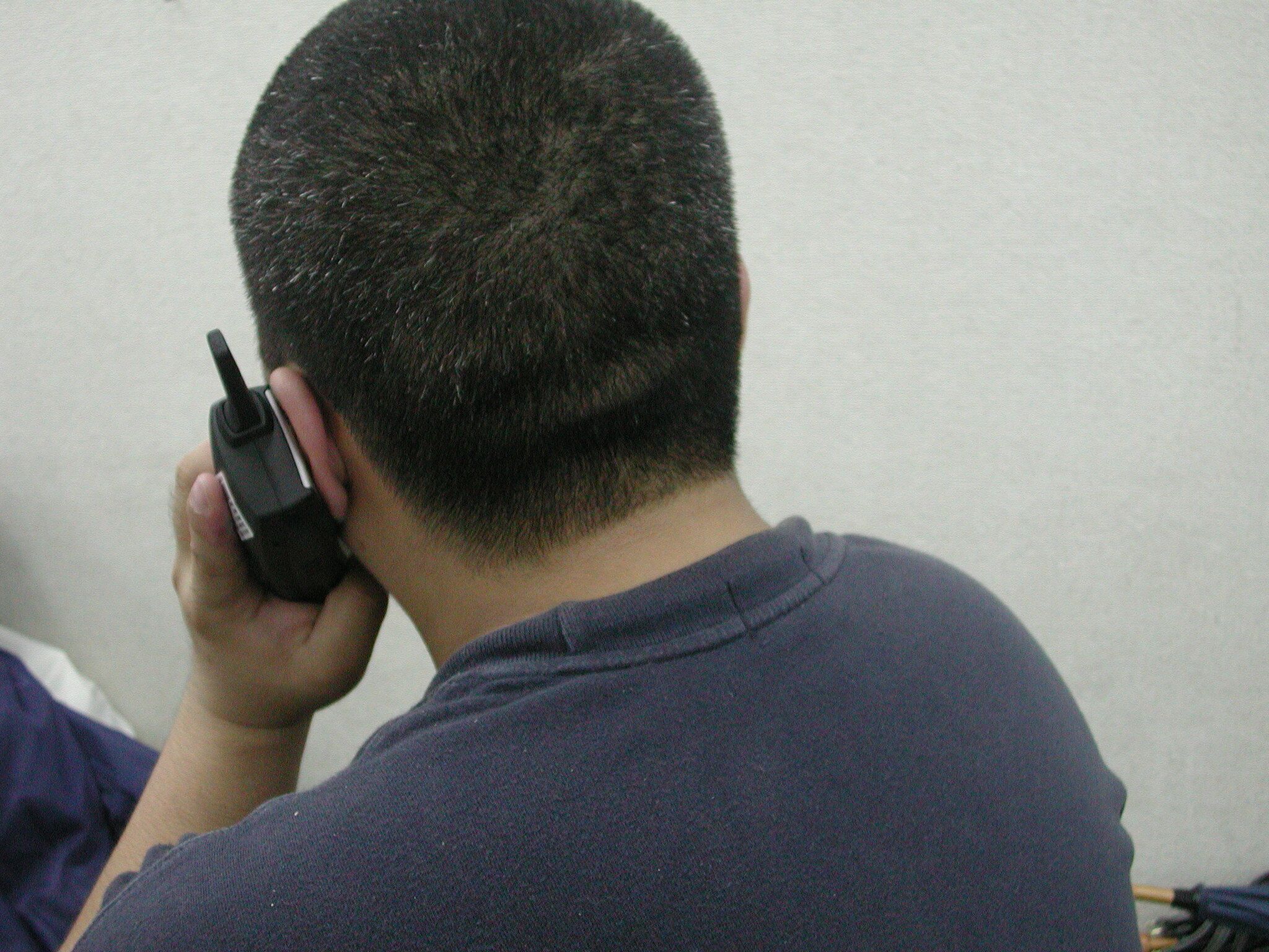
RF Safety information Maximum Conducted Output Power (mW) Measured Maximum F ield Strength @ 3m (dB μ μμ μ V/m) Calculated EIRP (mW) Base Unit74.1111.542.3 Handset131.8114.075.4 The FT901 operates at frequency range of 903.936MHz to 926.208MHz. With reference to Supplement C (Edition 97-01) to FCC OET Bulletin 65 Evaluating Compliance with FCC Guidelines for Human Exposure to Radio frequency Electromagnetic Fields, Spread Spectrum Cordless Phone handsets and transmitters that generally at above 300 mW EIRP, the potential for exceeding MPE and/or SAR limits is dependent on the design of the antenna and device operating conditions. From the above data, the maximum conducted power is 131.8 mW and the calculated EIRP is 75.4 mW, these low energy level ensures that the public is not exposed to radio frequency energy levels in excess of the Commission’s guild lines as stipulated in Parts 1.1307(b)(1) and 2.1093.
RF Exposure Info
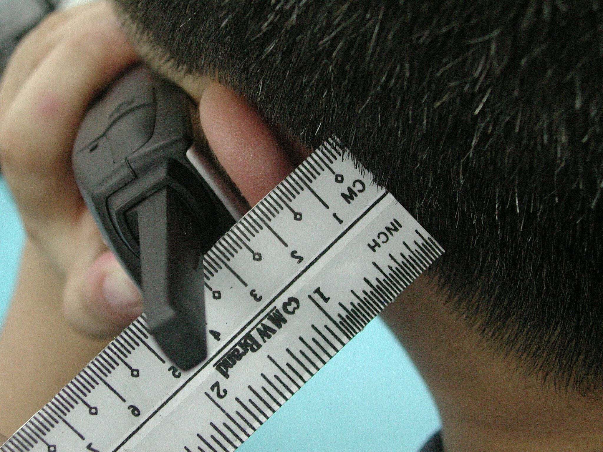
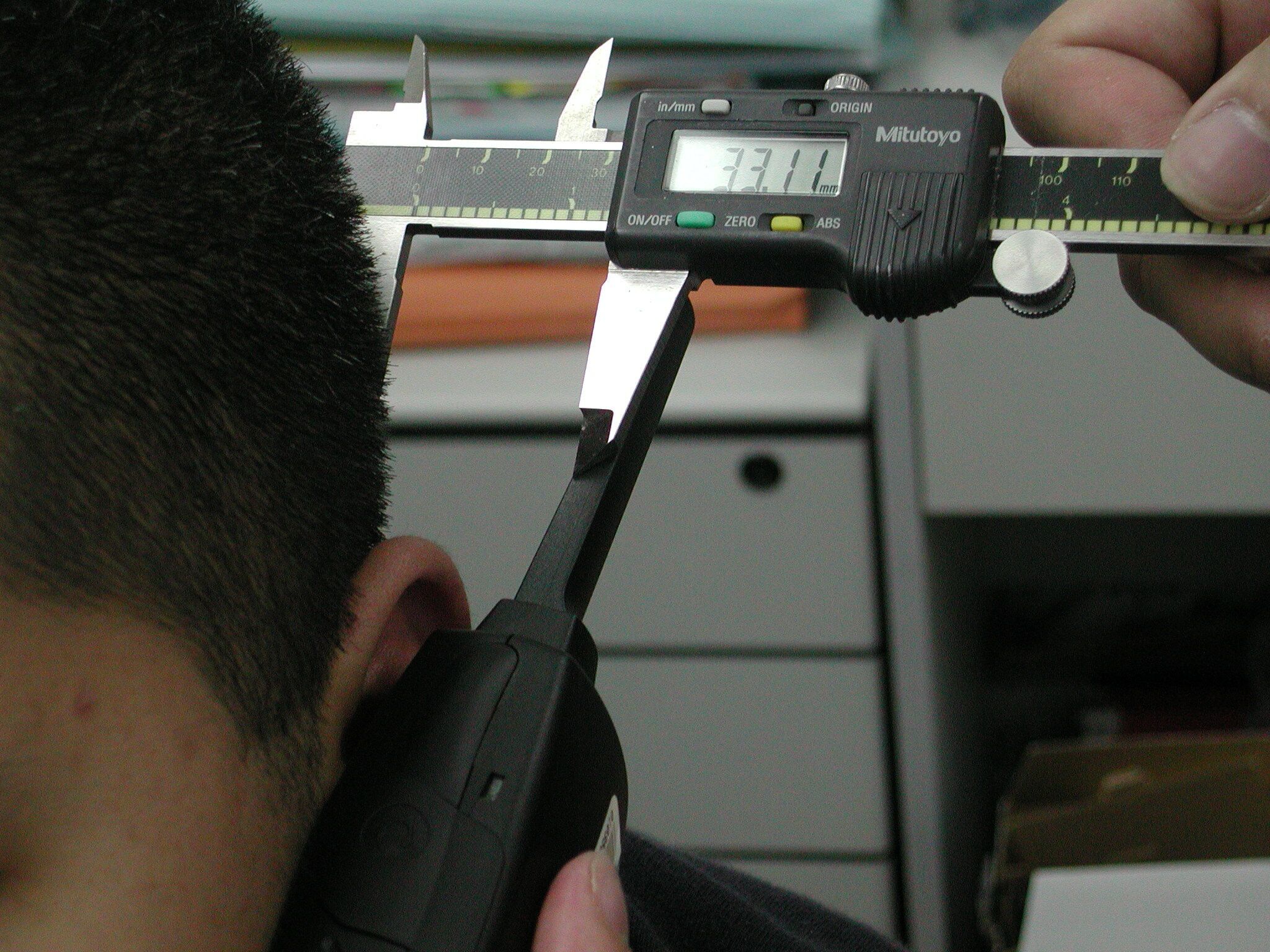
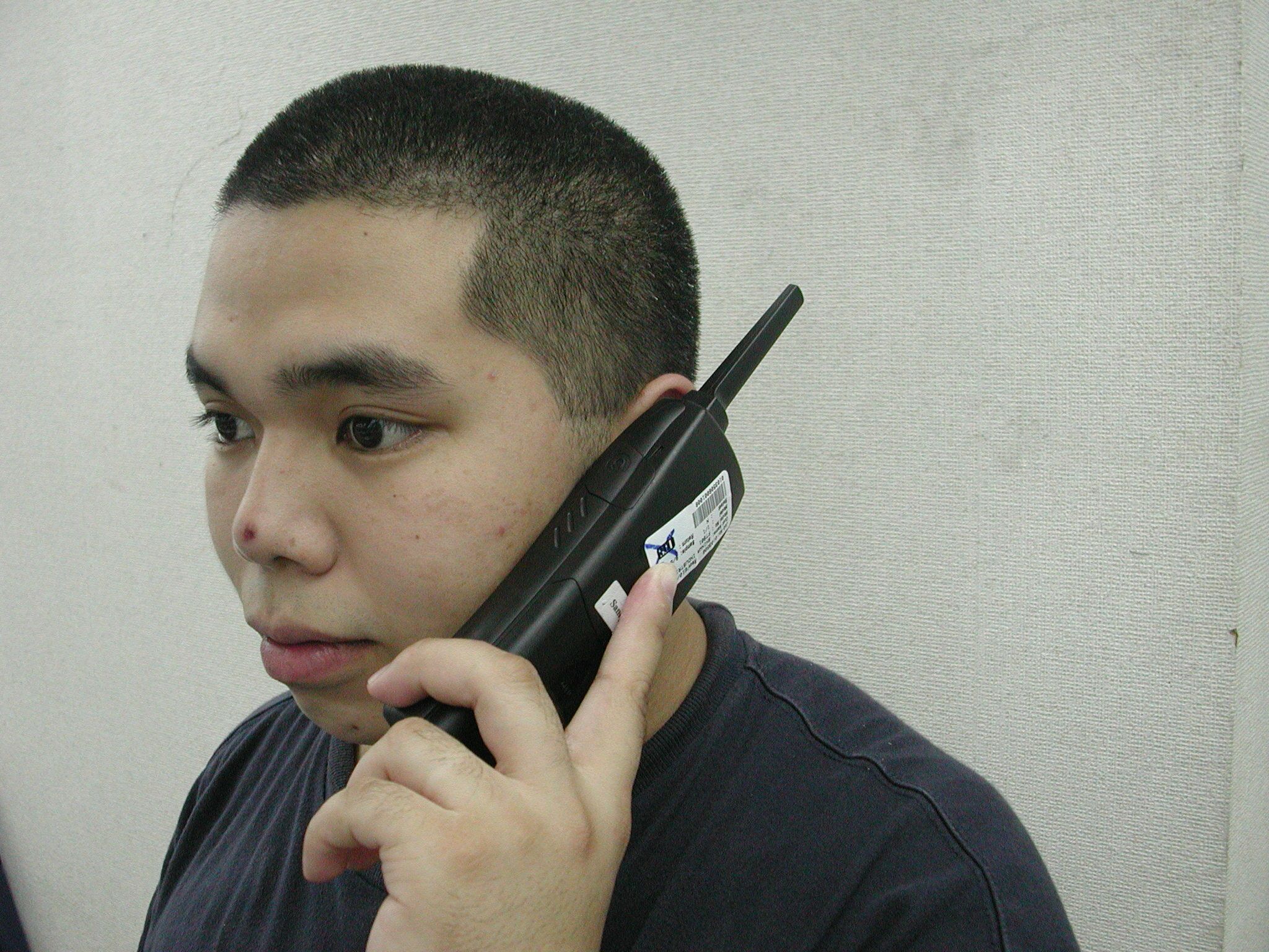
TEST REPORT Your Ref:Date: 27 Nov 2001 Our Ref: EMC/R/02318Page: 1 of 35 DID: 7729722Fax: 7776409 NOTE: This Report is not a Certificate of Quality. It is issued subject to the “ Terms and Conditions Governing Technical Services” set out in the “Request for Technical Services” form. The terms and conditions governing the issue of this report are set out overleaf. FORMAL REPORT ON TESTING IN ACCORDANCE WITH SAR (Specific Absorption Rate) Requirements using guidelines established in : FCC OET Bulletin 65 - Supplement C (Edition 97-01) OF A 900MHz Spread Spectrum Cordless Phone [ Model : FT901 ] TEST FACILITYTelecoms & EMC, Testing Group, PSB Corporation Pte Ltd 1 Science Park Drive, Singapore 118221 PREPARED FORRaymond Li World Symbol Ltd Unit 402, Wing Shan Tower, 173 Des Voeux Road, Central, Hong Kong. Tel : 852 28511188Fax : 852 28513636 MANUFACTURERShi Xue Song Shinwa Industries (China) Ltd 8 Ping Nan Zhong Road, Ping Nan Industrial Park, Zhong Kai No. 4 Road, Hui Zhou City, China. Tel : 752 2602373Fax : 752 2602401 JOB NUMBER56S00436 TEST PERIOD22 Nov 2001 – 25 Nov 2001 PREPARED BYAPPROVED BY ____________________ Gary Ng Ah Chye Associate Engineer ____________________ Teo Swee Hoe Senior Engineer LA-2001-0212-A LA-2001-0213-F LA-2001-0214-E LA-2001-0215-B Your product quality and safety mark LA-2001-0216-G LA-2001-0217-G PSB Corporation Pte Ltd •• Testing Group •• 1 Science Park Drive Singapore 118221 •• Tel 65 772 9620 •• Fax 65 775 9725 •• Email [email protected] •• Website www.psbcorp.com “The results reported herein, unless otherwise stated have been performed in accordance with the laboratory’s terms of accreditation under the Singapore Accreditation Council – Singapore Laboratory Accreditation Scheme” PSSB Corporation EMC/R/02318Shinwa Industries (China) LtdPage 2 of 35 900MHz Spread Spectrum Cordless Phone [ Model : FT901 ] This Report is issued under the following conditions: 1. Results of the testing/calibration in the form of a report will be issued immediately after the service has been completed or terminated. 2. Unless otherwise requested, a reported shall contain only technical results. Analysis and interpretation of the results and professional opinion and recommendations expressed thereupon, if required, shall be clearly indicated and additional fee paid for, by the Client. 3. This report is not a Certificate of Quality. It only applies to the sample of the specific product/equipment given at the time of its testing/calibration. The results are not used to indicate or imply that they are application to other similar items. In addition, such results must not be used to indicate or imply that PSB Corporation approves, recommends or endorses the manufacturer, supplier or user of such product/equipment, or that PSB Corporation in any way “guarantees” the later performance of the product/equipment. 4. The sample/s mentioned in this report is/are submitted/supplied/manufactured by the Client, PSB Corporation therefore assumes no responsibility for the accuracy of information on the brand name, model number, origin of manufacture, consignment or any information supplied. 5. Additional copies of the report are available to the Client at an additional fee. No third party can obtain a copy of this report through PSB Corporation, unless the Client has authorised PSB Corporation in writing to do so. 6. PSB Corporation may at its sole discretion add to amend the conditions of the report at the time of issue of the report and such report and such additions or amendments shall be binding on the Client. 7. All copyright in the report shall remain with PSB Corporation and the Client shall, upon payment of PSB Corporation’s fees for the carrying out of the tests/calibrations, be granted a license to use or publish the report to the third parties subject to the terms and conditions herein, provided always that PSB Corporation may at its absolute discretion be entitled to impose such conditions on the license as it sees fit. 8. Nothing in this report shall be interpreted to mean that PSB Corporation has verified or ascertained any endorsement or marks from any testing authority or bodies that may be found on that sample. 9. This report shall not be reproduced wholly or in parts and no reference shall be made by the Client to PSB Corporation or to the report or results furnished by PSB Corporation in any advertisements or sales promotion. PSSB Corporation EMC/R/02318Shinwa Industries (China) LtdPage 3 of 35 900MHz Spread Spectrum Cordless Phone [ Model : FT901 ] TABLE OF CONTENTS TEST SUMMARY PRODUCT DESCRIPTION TEST RESULTS ANNEX A-TEST INSTRUMENTATION & GENERAL PROCEDURES ANNEX B-TEST PHOTOGRAPHS / DIAGRAMS Test Setup EUT Photographs ANNEX C-TISSUE SIMULANT DATA SHEETS ANNEX D-REFERENCES PSSB Corporation EMC/R/02318Shinwa Industries (China) LtdPage 4 of 35 900MHz Spread Spectrum Cordless Phone [ Model : FT901 ] TEST SUMMARY The product was tested in accordance with the following standards. Test Results Summary Test StandardsDescription Pass / Fail SAR Measurement For Face-Hand Held Location Pass [ • FCC OET Bulletin 65-1997 (Supplement C) • ANSI/IEEE Standard C95.1- 1993 SAR Measurement For Waist Position with Belt-Clip Location Pass [ [Based on Spatial Peak Uncontrolled exposure / General population Level : Brain : 1.60 W/Kg Body : 1.60 W/Kg Modifications No modifications were made. PSSB Corporation EMC/R/02318Shinwa Industries (China) LtdPage 5 of 35 900MHz Spread Spectrum Cordless Phone [ Model : FT901 ] PRODUCT DESCRIPTION Description:The Equipment Under Test (EUT) is a 900MHz Spread Spectrum Cordless Phone. Model Number:FT901 Brand Name:FITTELS Radio Type:Cordless Phone Serial Numbers:Nil Frequency Band:903.936Mhz – 926.208MHz Operating Frequencies:903.936Mhz – 926.208MHz Rated Output Power: 17dBm – 20dBm Clock / Oscillator Type:PLL Type (Crystal Oscillator as reference) Clock / Oscillator Frequency :3.579MHz, 19.20MHz and 10.24MHz. Antenna Type:Integrated Antenna Signal Type:0.5G…
Text truncated - open the document above for the full version.
RF Exposure Info
PSSB Corporation EMC/R/02318Shinwa Industries (China) LtdPage 27 of 35 900MHz Spread Spectrum Cordless Phone [ Model : FT901 ] ANNEX B EUT Views Front of EUT Rear of EUT
RF Exposure Info
PSSB Corporation EMC/R/02318Shinwa Industries (China) LtdPage 15 of 35 900MHz Spread Spectrum Cordless Phone [ Model : FT901 ] ANNEX A TEST INSTRUMENTATION & GENERAL PROCEDURE PSSB Corporation EMC/R/02318Shinwa Industries (China) LtdPage 16 of 35 900MHz Spread Spectrum Cordless Phone [ Model : FT901 ] TEST INSTRUMENTATION & GENERAL PROCEDUREANNEX A A.1 General Test Procedure In the SAR measurement, the positioning of the probes must be performed with sufficient accuracy to obtain repeatable measurements in the presence of rapid spatial attenuation phenomena. The accurate positioning of the E-field probe is accomplished by using a high precision robot. The robot can be taught to position the probe sensor following a specific pattern of points. In a first sweep, the sensor is positioned as close as possible to the interface, with the sensor enclosure touching the inside of the fiberglass shell. The SAR is measured on a grid of points, which covers the curved surface of the phantom in an area larger than the size of the DUT. After the initial scan, a high- resolution grid is used to locate the absolute maximum measured energy point. At this location, attenuation versus depth scan will be accomplished by the measurement system to calculate the SAR value. PSSB Corporation EMC/R/02318Shinwa Industries (China) LtdPage 17 of 35 900MHz Spread Spectrum Cordless Phone [ Model : FT901 ] TEST INSTRUMENTATION & GENERAL PROCEDUREANNEX A A.2 Test Setup Phantom The phantom used in the evaluation of the RF exposure of the user of the wireless device is a clear fiberglass enclosure 1.5 mm thick, shaped like a human head or body and filled with a mixture simulating the dielectric characteristics of the brain, muscle or other types of human tissue. The maximum width of the cranial model is 17 cm, the cephalic index is 0.7 and the crown circumference of the cranial model is 61 cm. The ear is 6 mm above the outer surface of the shell. Simulated tissue Simulated Tissue: Suggested in a paper by George Hartsgrove and colleagues in University of Ottawa Ref.: Bioelectromagnetics 8:29-36 (1987) This simulated tissue is mainly composed of water, sugar and salt. At higher frequencies, in order to achieve the proper conductivity, the solution does not contain salt. Also, at these frequencies, D.I. water and alcohol is preferred. Tissue Density : Approximately 1.25 g/cm 3 • Preparation We determine the volume needs and carefully measure all components. A clean container is used where the ingredients will be mixed. A stirring paddle and a hand drill is used to stir the mixture. First we heat the water to about 40 o C to help the ingredients to dissolve and then we pour the salt and the bactericide. We stir until all the ingredients are completely dissolved. We continue stirring slowly while adding the sugar. We avoid high RPM from the mixing device to prevent air bubbles in the mixture. Later on, we add the HEC to maintain the solution homogeneous. Mixing time is approximately 30 to 40 min. • Measurement of Electrical Characteristics of Simulated Tissue 1) Agilent 8753ES, S-Parameter Network Analyzer (30KHz – 6GHz) 2) Slotted Coaxial Waveguide • Description of the slotted coaxial waveguide The cylindrical waveguide is constructed with copper tube of about 30 to 40 cm of length, generally 12.5 mm diameter, with connectors at both ends. Inside of this tube, a conductive rod about 6.3 mm is coaxial supported by the two ends connectors (radiator). A slot 3 mm wide start at the beginning of the tube to almost the two third of the tube length. The outer edge of the slotted tube is marked in centimeters. For frequency below 1GHz, 1 centimeter per step. For higher frequency above 1 GHz, 0.5 centimeter per step. A saddle piece containing the sampling probe is inserted in the slot so the tip of the probe is close but not in contact with the inner conductor (radiator). To measure the electrical characteristics of the liquid simulated tissue, which fill the coaxial waveguide, select CW frequency and measure amplitude and phase with the Network Analyzer for every point in the slot (typically 11). An effort is made to keep the results dielectric constant and conductivity within 5 % of published data. PSSB Corporation EMC/R/02318Shinwa Industries (China) LtdPage 18 of 35 900MHz Spread Spectrum Cordless Phone [ Model : FT901 ] TEST INSTRUMENTATION & GENERAL PROCEDUREANNEX A Electrical Characteristics Measurement Setup (S/m) 108.854f2S = )1( = )'(2 tan = S 4 = ' 4 )+(A = inches 54.2 100 f c = 360 2 = 1 ln 20 A =A m/s 103 = c r 12 2 r 2 222 10 8 επσ ε ε θ επ λ θ π λθ ε λ πθ θ ⋅⋅⋅⋅⋅ + ⋅ ⋅ ⋅ ⋅∆ ∆ ⋅ S A m re re re where; A is the amplitude attenuation in dB è is the phase change in degrees for 5 cm of wave propagation in the slotted line f is the frequency of interest in Hz PSSB Corporation EMC/R/02318Shinwa Industries (China) LtdPage 19 of 35 900MHz Spread Spectrum Cordless Phone [ Model : FT901 ] TEST INSTRUMENTATION & GENERAL PROCEDUREANNEX A Conversion Factor and SAR Value Calculation The measurement system consists of an E-field probe, instrumentation amplifiers, RF transparent cable connecting the amplifiers to the computer, the robotics arm with its extension and proximity sensors, a phantom with simulated tissue and a radio holder to support the device under test. The E-field probe is a three channel device used to measure RF electric fields in the near vicinity of the source. The three sensors are mutually orthogonal positioned dipoles, and are constructed over a quartz substrate. Located in the center of the dipole is a Schottky diode. High impedance lines are connecting the sensor to the amplifier and then optically linked to the computer. The probe has an isotropic response and is transparent to the RF fields. • Calibration is performed by two steps: 1) Determination of free space E-field from amplified probe outputs in a test RF field. This calibration is performed in a TEM cell when the frequency is below 1 GHz and in a waveg…
Text truncated - open the document above for the full version.
Test Report
• The test results rep orted in this rep ort shall refer only to the samp le actually tested and shall not refer or be deemed to refer to bulk from which such a samp le may be said to have been obtained. • This rep ort shall not be rep roduced excep t in full without p rior authorization form Giant Electronics Limit ed Limit ed FCC ID: PRWFT901 Inte rte k Te sting Se rvice s Hong Kong Ltd. 2/F., Garment Centre, 576 Castle Peak Road, Kowloon, Hong Kong. Tel: (852) 2173 8888 Fax: (852) 2741 1693 World Symbol Ltd. Application For Certification 900MHz Direct Sequence Spread Spectrum Cordless Phone (FCC ID: PRWFT901) WO# 0103504 WL/Sandy August 7, 2001 INTERTEK TESTING SERVICE FCC ID: PRWFT901 i LIST OF EXHIBITS INTRODUCTION EXHIBIT 1: Summary of Tests EXHIBIT 2 :General Description EXHIBIT 3 :System Test Configuration EXHIBIT 4 :Measurement Results EXHIBIT 5 :Equipment Photographs EXHIBIT 6 :Product Labelling EXHIBIT 7 :Technical Specifications EXHIBIT 8 :Instruction Manual EXHIBIT 9 :Security Code Information INTERTEK TESTING SERVICE FCC ID: PRWFT901 ii MEASUREMENT/TECHNICAL REPORT World Symbol Ltd. - MODEL: FT901 FCC ID: PRWFT901 This report concerns (check one)Original Grant X Class II Change Equipment Type: DSS-Part 15 Spread Spectrum Transmitter Deferred grant requested per 47 CFR 0.457(d)(1)(ii)?Yes No X If yes, defer until : date Company Name agrees to notify the Commission by: date of the intended date of announcement of the product so that the grant can be issued on that date. Transition Rules Request per 15.37?Yes No X If no, assumed Part 15, Subpart C for intentional radiator - the new 47 CFR [10-1-96 Edition] provision. Report prepared by:Wilson Loke Intertek Testing Service 2/F., Garment Centre, 576 Castle Peak Road, Kowloon, Hong Kong. Phone:852-2173-8575 Fax:852-2741-1693 INTERTEK TESTING SERVICE FCC ID: PRWFT901 iii Table of Contents 1.0 Summary of test results .......................................................................................1 2.0 General Description ................................................................................................................ 2 2.1 Product Description ............................................................................................................... 4 2.2 Related Submittal(s) Grants ................................................................................................... 5 2.3 Test Methodology .................................................................................................................. 5 2.4 Test Facility............................................................................................................................ 5 3.0 System Test Configuration ...................................................................................................... 7 3.1 Justification............................................................................................................................. 7 3.2 EUT Exercising Software ....................................................................................................... 7 3.3 Support Equipment List and Description ............................................................................... 8 3.4 Equipment Modification......................................................................................................... 9 4.0 Measurement Results ............................................................................................................ 11 4.1 Maximum Conducted Output Power at Antenna Terminals ................................................ 11 4.2 Minimum 6dB RF Bandwidth .............................................................................................. 13 4.3 Maximum Power Density ..................................................................................................... 15 4.4 Out of Band Conducted Emissions....................................................................................... 17 4.5 Out of Band Radiated Emissions.......................................................................................... 18 4.6 Transmitter Radiated Emissions in Restricted Bands........................................................... 18 4.7 Field Strength Calculation .................................................................................................... 19 4.8 Radiated Emission Configuration Photograph - Base Unit .................................................. 20 4.9 Radiated Emission Data - Base Unit .................................................................................... 21 4.10 Radiated Emission Configuration Photograph - Handset ................................................... 25 4.11 Radiated Emission Data - Handset ..................................................................................... 26 4.12 AC Line Conducted Emission ............................................................................................ 30 4.13 Line Conducted Configuration Photograph - Base Unit .................................................... 31 4.14 Line Conducted Emission Configuration Data................................................................... 32 4.15 Radiated Emission from Digital Section of Transceiver..................................................... 33 4.16 Processing Gain Measurements.......................................................................................... 36 4.17 Transmitter Duty Cycle Calculation and Measurements.................................................... 36 5.0 Equipment Photographs ....................................................................................................... 42 6.0 Product Labelling .................................................................................................................. 44 7.0 Technical Specifications ........................................................................................................ 46 8.0 Instruction Manual .....…
Text truncated - open the document above for the full version.
Test Report
Intertek Testing Services Company: World Symbol Ltd.Date of Test: Nov 25, 2001 Model: FT901 Maximum Conducted Output Power at Antenna Terminals, FCC Rules 15.247(b) - Continued: (Handset Unit) Maximum Antenna Gain = 2 dB (loss) Frequency (MHz)Output in dBmOutput in mW Low Channel:903.93618.672.4 Middle Channel: 914.68818.570.8 High Channel: 926.20818.367.6 Cable loss : 0.5 dB External Attenuation : 0 dB Cable loss, external attenuation: [ ] included in OFFSET function [ x ] added to SA raw reading
Test Setup Photos
Configuration Photographs FCC ID: PRWFT901 Radiated Emission – Base Front View Re ar Vie w Configuration Photographs FCC ID: PRWFT901 Radiated Emission – Handset Front View Re ar Vie w Configuration Photographs FCC ID: PRWFT901 Conducted Emission Front View Re ar Vie w Configuration Photographs FCC ID: PRWFT901 Conducted Emission Side View
Test Setup Photos
Configuration Photographs FCC ID: PRWFT901 Radiated Emission – Base Front View Re ar Vie w Configuration Photographs FCC ID: PRWFT901 Radiated Emission – Handset Front View Re ar Vie w Configuration Photographs FCC ID: PRWFT901 Conducted Emission Front View Re ar Vie w Configuration Photographs FCC ID: PRWFT901 Conducted Emission Side View
Test Setup Photos
Configuration Photographs FCC ID: PRWFT901 Radiated Emission – Base Front View Re ar Vie w Configuration Photographs FCC ID: PRWFT901 Radiated Emission – Handset Front View Re ar Vie w Configuration Photographs FCC ID: PRWFT901 Conducted Emission Front View Re ar Vie w Configuration Photographs FCC ID: PRWFT901 Conducted Emission Side View
Contact Information
Applicant
Shi Xue Song(Vice General Manager)
Technical Contact
Intertek Testing Services Hong Kong Ltd.Wilson Loke
[email protected](852) 2173 8575
2/F., Garment Centre, · Kowloon · Hong Kong
Non-Technical Contact
Intertek Testing Services Hong Kong Ltd.Wilson Loke
[email protected](852) 2173 8575
Test Firm
Intertek Testing Services Hong KongBilly Chow
Technical Specifications
| # | Rule Parts | Frequency Range | Power Output |
|---|---|---|---|
| 2 | 15C | 903.936 MHz - 926.208 MHz | 72.00 mW |