FCCID.CO- FCC ID Database
HomeCompaniesEquipment ClassesSearch

© 2026 FCC ID Database. All rights reserved.

AboutContactData sourced from FCC public records
  1. Home/
  2. Dataview Co., Ltd./
  3. PRXDAVI-1500N

PRXDAVI-1500N15" LCD MONITOR

Dataview Co., Ltd.
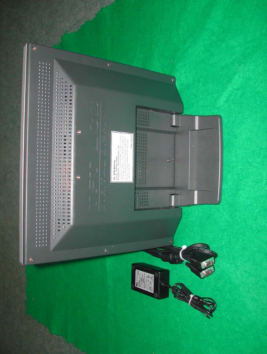
15" LCD MONITOR - FCC ID PRXDAVI-1500N - Dataview Co., Ltd.
Click to zoom

Application Details

Equipment Class
JBP - Part 15 Class B Computing Device Peripheral
Date of Grant
Dec 28, 2003
Application Purpose
Original Equipment
Date of Application
Dec 28, 2003
Equipment Note
15" LCD MONITOR
Company
Dataview Co., Ltd.
Country
South Korea

Documents & Files

Select a file to view

Users Manual

↗
↗

Block Diagram

↗

External Photos

↗

ID Label/Location Info

↗
↗

Internal Photos

↗

Operational Description

↗

Schematics

↗
↗

Test Report

↗

Test Setup Photos

↗

Document Text

Text extracted from the exhibit documents filed with the FCC. Open a document above to read the original.

Users Manual

USER'S MANUAL Ver DN1.0E 18.1£¢ TFT LCD Monitor With A/V & TV 17£¢ TFT LCD Monitor With A/V & TV 15£¢ TFT LCD Monitor With A/V LCD MONITOR ANALOG COLOR TFT USER'S MANUAL LCD MONITOR USER'S MANUAL TABLE OF CONTENTS Safety Instructions 2 General Safety Precautions 3 6 7 9 10 11 8 9 12 13 ¥°. Parts Description Front Panel (15£¢) Front Panel (17£¢) Front Panel (18.1£¢) Rear Panel (15£¢) Rear Panel (17£¢) Rear Panel (18.1£¢) Accessory Remote control Unit Remote key instruction Connecting a PC Connecting the VCR, DVD, TV or Other External Device 5 4 ¥ ́. APPENDIX 20 21 Specification Mode ¥³. OSD MENU 17 18 19 MONITOR OSD MENU VIDEO / S-VIDEO OSD MENU TV OSD MENU 14 15 15 ¥±. Before using the monitor Instructions Initial set PC mode When the Screen is unstable or the TV Channel does not change ¥². OSD MENU Tree 16 1. Before connecting the AC power cord to the DC adapter outlet, make sure the voltage designation of the DC adapter corrsponds to the local electrical supply. 2. Never insert anything metallic into the cabinet openings of the Liquid Crystal Display (LCD) monitor; doing so may create the danger of electric shock. 3. To avoid electric shock, never touch the inside of the LCD monitor. Only a qualified technician should open the case of the LCD monitor. 4. Never use your LCD monitor if the power cord has been damaged. Do not allow anything to rest on the power cord, and keep the cord away from areas where people can trip over it. 5. Be sure to hold the plug, not the cord, when disconnecting the LCD monitor from an electric socket. 6. Openings in the LCD monitor cabinet are provided for ventilation. To prevent overheating, these openings should not be blocked or covered. Also, avoid using the LCD monitor on a bed, sofa, rug or other soft surface. Doing so may block the ventilation openings in the bottom of the cabinet. If you put the LCD monitor in a bookcase or some other enclosed space, be sure to provide adequate ventilation. 7. Put your LCD monitor in a location with low humidity and a minimum of dust. 8. Do not expose the LCD monitor to rain or use it near water (in kitchens, near swimming pools, etc.). If the LCD monitor accidentally gets wet, unplug it and contact an authorized dealer immediately. You can clean the LCD monitor with a damp colth when necessary, but be sure to unplug the LCD monitor first. 9. Place the LCD monitor on a solid surface and treat it carefully. The screen is made of thin glass with a plastic front surface and can be damaged if dropped, hit or scratched. Do not clean the front panel with keton-type materials (e.f., acetone), Ethyl alcohol, Toluene, Ethyl acid, Methyl or Chloride - these may damage the panel. 10. Locate your LCD monitor near an easily accessible AC outlet. 11. If your monitor does not operate normally - in particular, if there are any unusual sounds or smells comming from it - unplug it immediately and contact an authorized dealer or service center. 12. High temperature can cause problems. Don't use your LCD monitor in direct sunlight and keep it away from fireplaces, and other sources of heat. 13. Unplug the LCD monitor when it is going to be left unused for an extended period of time. 14. Unplug your LCD monitor from the AC outlet before any service. Safety Instructions CAUTION : TO REDUCE THE RISK OF ELECTRIC SHOCK, DO NOT REMOVE COVER. This user's manual has been engineered and manufactured for your safety. You can prevent serious electrical shock and hazards by keeping in mind the following : Do not place anything such like heavy, wet or magnetic one on the monitor or the power cord. Never cover the ventilation openings with any material and never touch them with metallic or inflammable materials. Avoid operating the monitor in extreme heat, humidity or areas affected by dust. £ª Temperature : 5-35¡É £ª Humidity : 30-80RH Do not use a solvent, such as benzene, to clean the monitor, as it will damage the LCD surface. Do not use sharp tools such as a pin or a pencil near the monitor, as they may scratch the LCD surface. Overloaded AC outlets and extension cords are dangerous, as are frayed power cords and broken plugs, which may cause electric shock or fire call your service technician for replacement. Be sure to turn the monitor off before plugging the power cord into the socket. Make sure that the power cord and other cords are securely and correctly connected. General Safety Precautions RISK OF ELECTRIC SHOCK LCD MONITORLCD MONITOR USER'S MANUALUSER'S MANUAL SPEAKER MENU SEL LED ¡ã ¡å SPEAKER LCD MONITOR ¥°. Parts Description Front Panel (15£¢) 1) MENU ¡¤Displays the main MENU ¡¤In MENU window, moves to upper menu 2) MENU ¡¤Displays the main MENU ¡¤In MENU window, moves to upper menu USER'S MANUAL LCD MONITOR ¥°. Parts Description Front Panel (17£¢) USER'S MANUAL 3) ¡ã, ¡å ¡¤In PC or Video mode, controls the volume ¡¤In MENU window, increase or decrease the value 5) ¡ã, ¡å ¡¤In MENU window, increase or decrease the value ¡¤In PC or VIDEO mode, controls the volume ¡¤In TV mode, controls the channel 5) LED ¡¤Green light when power - on ¡¤Yellow blinking when no signal ¡¤Power on or off 4) ¡¤Power on or off 6) 6) SPEAKER 7) LED ¡¤Green light when power - on ¡¤Blinking when no signal 8) SPEAKER ¡¤Selects input signal (PC, VIDEO) ¡¤In MENU window, move to sub menu 2) SEL ¡¤Selecting input signal (PC, VIDEO, TV) ¡¤In MENU window, move to sub menu 3) SEL 1) SENSOR ¡¤Remote control sensor 4) AUTO ¡¤In PC mode, configures the display automatically SPEAKER SENSOR MENU SEL AUTO LED ¡ã ¡å SPEAKER ̈ç ̈è ̈é ̈ê ̈ë ̈ì ̈í ̈î ̈î MENU SEL AUTO POWER VOL ¡¤Power on or off 6) 5) LED ¡¤Green light when power - on ¡¤Blinking when no signal 7) ¡ã, ¡å ¡¤In MENU window, increase or decrease the value ¡¤In PC or VIDEO mode, controls the volume ¡¤In TV mode, controls the channel 8) SPEAKER 1) MENU ¡¤Displays the main MENU ¡¤In MENU window, moves to upper menu ¡¤Selecting input signal (PC, VIDEO, TV) ¡¤In MENU window, move to sub menu 2) SEL 3) SENSOR ¡¤Remote co…

Text truncated - open the document above for the full version.

Users Manual

17£¢ 15£¢ Connecting a PC 1. Turn off your computer and monitor. 2. Connect a PC D-Sub (VGA) cable between your PC and VGA of the monitor. And then fasten the screws of both sides of the cable. 3. Connect a DC Power cable to the power input jack of the monitor. 4. Power on the computer before turning on the monitor. LCD MONITOR USER'S MANUAL ¥°. Parts Description POWERVGAS-VIDEOVIDEO INAUDIOPC AUDIO RLINOUT TV ANT VGAS-VIDEOVIDEO INOUT AUDIO LR AUDIO TV ANTDC POWER 18.1£¢ VGAS-VIDEOVIDEO IN INOUT PC AUDIO LR AUDIO TV ANTDC POWER POWERVGAS-VIDEOVIDEO INAUDIOPC AUDIO RLINOUT TV ANT 18.1£¢ 17£¢ 15£¢ Connecting the VCR, DVD, TV or Other External Device LCD MONITOR USER'S MANUAL To view television channels correctly, a signal must be received by the set from one of following sources : £ª An outdoor aerial £ª An indoor aerial (not recommendable) £ª A cable television network 1. In the first three cases, connect the aerial or network input cable to the 75 ohm coaxial socket on the bottom of the television. 2. Press the TV mode button on the remote controller. (TV Function is optional with users.) ¥°. Parts Description 1. Connect video and audio cable according to the sharpe and color of the video/audio cable. £ª When an external device is in MONO, the audio connection cable can be connected to either the left or the right and S.MODE should be set FM MONO. 2. For optimal visual image, use S-VIDEO connector instead of video (yellow) connector. ¥±. Before using the monitor LCD MONITOR USER'S MANUAL - This monitor conforms to VESA DPMS regulations - This monitor has tested and passed all the regulations regarding electromagnetic interference - The brightness of upper and lower part of the screen could be seen different because of viewing angle - The LCD panel consists of 3,840¡¿3,072 dots so some dots can be seen as bright or dark but never affects the monitor function - The optimum resolution is 1,280¡¿1,024 at 60Hz, so check with your PC graphic card - When your display status is not good enough to look, press ¡°AUTO¡± key - Please use only the adaptor supplied with the monitor otherwise you will not be able to receive free A/S when out of order - There could be noises in particular graphic card of your PC, then adjust manually by changing the values of phase or clock - There are VESA mount holes in the back of your monitor for wall-mount Instructions SELECTPOWER SCAN PC AUTO EXIT TV MUTE 1 2 3 4 5 6 7 8 9 0 MENU CH ¡ã VOL + CH ¡å VOL - ¡Ø There will be some noises under the Certain VGA card. When the noise would not disappear Auto adjustment, adjust manually. 4. Close the MENU window and press AUTO button 2. Use ¡ã, ¡å button, select¡°MISCELLANEOUS¡± 3. Select initialize 5. 15£¢ is select¡°AUTO¡± in the OSD menu window 1. Press MENU button, the main menu is displayed When the Screen is unstable or the TV channel does not change LCD MONITOR USER'S MANUAL 3. Before operation, set the PC resolution by 1280¡¿1024, and true color (15£¢ 1024¡¿768) 2. Press the PC button on the remote controller to switch to the PC mode Then the PC screen is automatically set. When a CD-Title runs, the music can be heard from the speakers 1. Power on your monitor by pressing the POWER button on the main set or on the remote controller Initial set PC mode ¥±. Before using the monitor MONITOR OSD MENUMONITOR OSD MENU VIDEO/S-VIDEO OSD MENU TV OSD MENU ¥². OSD MENU¥³. OSD MENU LCD MONITOR USER'S MANUAL BRIGHTNESS :BRIGHTNESS : CONTRAST :CONTRAST : COLOR CONTROL :COLOR CONTROL : MISCELLANEOUS :MISCELLANEOUS : SOUND :SOUND : AUTO (AUTO ADJUST) :AUTO (AUTO ADJUST) : LANGUAGE :LANGUAGE : H-V POSITION :H-V POSITION : CLOCK PHASE :CLOCK PHASE : INPUT :INPUT : Adjusts brightness Adjusts contrast - Adjusts the color temperature - User can adjusts the color temperature by adjusting values of red, green, blue - INITIALIZE : Sets all the values to factory setting values - OSD TIMER : Adjusts the OSD menu activating time (5 sec to 100 sec) - OSD POSITION : Adjusts the horizontal / vertical position of OSD menu window - VOLUME : Adjusts the volume level of AMP - MUTE : Set the speaker on or off - TREBLE : Adjusts the treble - BASE : Adjusts the base Auto adjusting Selects the language of OSD menu (ENGLISH, FRANCE, DUTCH, ITALIANO, ESPANO, DEUTCH, SVENSKA, SUOMI, DANSK, PORTUGUES) - H. POSITION : Adjusts the horizontal position of picture - V. POSITION : Adjusts the vertical position of picture - PHASE : Adjusts phase - CLOCK : Adjusts clock Selects input signal - RGB : PC signal select - SVHS : SUPER VIDEO signal select - COMPOSITE VIDEO : Composite signal select - TV : TV signal select LCD MONITOR USER'S MANUAL BRIGHTNESS :BRIGHTNESS : CONTRAST :CONTRAST : COLOR ADJUST :COLOR ADJUST : MISCELLANEOUS :MISCELLANEOUS : SOUND :SOUND : LANGUAGE : LANGUAGE : TV :TV : INPUT :INPUT : Adjusts brightness Adjusts contrast - SATURATION : Adjusts the color - TINT : Adjusts the tint - SHARPNESS : Adjusts the sharpness - INITIALIZE : Sets all the values to factory setting values - OSD TIMER : Adjusts the OSD menu activating time (5 sec to 100 sec) - OSD POSITION : Adjusts the horizontal / vertical position of OSD menu window - VOLUME : Adjusts the volume level of AMP - MUTE : Set the speaker on or off - TREBLE : Adjusts the treble - BASE : Adjusts the base (MISCELLANEOUS) Selects the language of OSD menu (ENGLISH, FRANCE, DUTCH, ITALIANO, ESPANO, DEUTCH, SVENSKA, SUOMI, DANSK, PORTUGUES) Nonsupported Selects input signal - RGB : PC signal select - SVHS : SUPER VIDEO signal select - COMPOSITE VIDEO : Composite signal select - TV : TV signal select VIDEO / S-VIDEO OSD MENU ¥³. OSD MENU¥³. OSD MENU LCD MONITORLCD MONITOR USER'S MANUALUSER'S MANUAL TV OSD MENU BRIGHTNESS :BRIGHTNESS : CONTRAST :CONTRAST : COLOR ADJUST :COLOR ADJUST : MISCELLANEOUS :MISCELLANEOUS : SOUND :SOUND : LANGUAGE :LANGUAGE : Adjusts brightness Adjusts contrast - SATURATION : Adjusts the color - TINT : Adjusts the tint - SHARPNESS : Adjusts the sharpness - INITIALIZE : Sets all t…

Text truncated - open the document above for the full version.

Block Diagram

NST_RTA_15 1.0 ODD 8 SPEARK OUT RGB IN 12V ONLY VGA KEY B/D ANALOG PART INVERTER SCA / SDA OSDAUDIO 24C04 MCU PART LVDS 30P SCALER : RTD2022 INVERTERD-SUB EVEN 8 AUDIO MAIN AMP DIGITAL PART SINGLE POWERAUDIO OUTPUT CONNECTOR EEP ROM POWER LCD OUTPUT AUDIO INPUT MEMORY CLOCK: 24.000MHz TYPE: SMD, C0:18pF MAIN CLOCK: 24.576MHz TYPE: SMD, C0:18pF MAIN CLOCK 24.576MHz MCU CLOCK 24.000MHz

External Photos

SK TECH CO., LTD. Page 1 of 2 SKT SKTFCE-031226-208 FCC ID : PRXDAVI-1500N External Photographs of EUT SK TECH CO., LTD. Page 2 of 2 SKT SKTFCE-031226-208 FCC ID : PRXDAVI-1500N

ID Label/Location Info

SK TECH CO., LTD. Page 1 of 1 SKT SKTFCE-031226-208 FCC ID : PRXDAVI-1500N FCC ID Sample Label & Location Information LABELLING REQUIREMENTS PER ∫∫∫∫2.928 The Label shown shall be permanently affixed at a conspicuous location on the device and be readily visible to the user at the time of purchase.

ID Label/Location Info

SK TECH CO., LTD. Page 1 of 1 SKT SKTFCE-031226-208 FCC ID : PRXDAVI-1500N FCC ID Label Sample 15” LCD Monitor FCC ID : PRXDAVI-1500N Manufacturer : DATAVIEW CO., LTD. This device complies with part 15 of the FCC Rules. Operation is subject to the following two conditions: (1)This device may not cause harmful interference, and (2) this device must accept any interference received, including interference that may cause undesired operation. Made in Korea

Internal Photos

SK TECH CO., LTD. Page 1 of 10 SKT SKTFCE-031226-208 FCC ID : PRXDAVI-1500N Internal Photographs of EUT SK TECH CO., LTD. Page 2 of 10 SKT SKTFCE-031226-208 FCC ID : PRXDAVI-1500N SK TECH CO., LTD. Page 3 of 10 SKT SKTFCE-031226-208 FCC ID : PRXDAVI-1500N SK TECH CO., LTD. Page 4 of 10 SKT SKTFCE-031226-208 FCC ID : PRXDAVI-1500N SK TECH CO., LTD. Page 5 of 10 SKT SKTFCE-031226-208 FCC ID : PRXDAVI-1500N SK TECH CO., LTD. Page 6 of 10 SKT SKTFCE-031226-208 FCC ID : PRXDAVI-1500N SK TECH CO., LTD. Page 7 of 10 SKT SKTFCE-031226-208 FCC ID : PRXDAVI-1500N SK TECH CO., LTD. Page 8 of 10 SKT SKTFCE-031226-208 FCC ID : PRXDAVI-1500N SK TECH CO., LTD. Page 9 of 10 SKT SKTFCE-031226-208 FCC ID : PRXDAVI-1500N SK TECH CO., LTD. Page 10 of 10 SKT SKTFCE-031226-208 FCC ID : PRXDAVI-1500N

Operational Description

SK TECH CO., LTD. Page 1 of 1 SKT SKTFCE-031226-208 FCC ID : PRXDAVI-1500N Operational Description I. Installing the Video Driver To install the video driver, refer to the following sequence. Select Start/Setting/Control Panel. Click Add New Hardware. Click Next. Click Next after selecting No, the device isn’t in the list. Click Next after selecting No, I want to select the hardware from a list. Click Next after selecting Monitors. Click Have Disk... Insert the supplied CD Drive. Select OK. Select Next after selecting the same model which you purchased. Click Finish.

Schematics

NST_RTA_15 1.0 R525 R EL56 CAP-EL J501 PHONE JACK 5PIN 1 2 3 4 5 OUT R EL55 CAP-EL C502 CAP R523R +12V R503 RES R510 CAP NP_1 EL58 CAP-EL R524R U501 tda7496l_9 1 2 3 4 5 6 7 8 9 10 11 12 13 14 15 16 17 18 19 20 GND GND GND IN L VAROUT L VOLUME VAROUT R NC IN R SVR STBY MU TE GND OUT R VR VR OUT L GND GND GND R522 R_1 C504 CAP BD50 BEAD_1 EL57 CAP-EL R527 R J503 WAFER 3PIN_0 1 2 3 4 1 2 3 4 MU TE R519 R_1 R526 R C506 CAP OUT L C501 CAP VOLUME2 J502 PHONE JACK 5PIN 1 2 3 4 5 R502 RES EL59 CAP-EL C507 CAP NST_RTA_15 1.0 12V_INV D101 DIODE BOM삭제 J1 PHONEJACK 12V 3AVCC1 ADC_ 3AVCC 3DVCC +C104 CAPACITOR POL RTD 2.5DVCC +5VM BD101INDUCTOR IRON C105 CAP NP 5DVCC C106 CAP NP C108 CAP NP + C101 CAP POL L101 INDUCTOR R102 R + C107 CAP POL SOT-89 SMD TYPE 3AVCC3 5DVCC LVDS_3AVCC + C109 CAPACITOR POL 3PVCC U103 IRF7416_2 1 3 2 4 5 VI GND VO F/B S/T 12V + C110 CAP POL RTD 3DVCC BD102 INDUCTOR D102 DIODE ZENER2_1 RTD 3PVCC MCU_VCC + C103 CAP POL U101 LT1585_0 1 23 AD J VOVI 2.5DVCC R101 R + C102 CAP POL U102 LT1585_2 1 32 GND VIVO NST_RTA_15 1.0 R G B NC DGND RAGND GAGND BAGND NC DGND NC DDCSDA DDCSCL HSIN VSIN U11 VGA_CON15 1 2 3 4 5 6 7 8 9 10 11 12 13 14 15 C204 CAP NP R3DVCC 3AVCC1 DDC_SDA C230 CAP NP C227 CAP NP 3DVCC RXEIN0+ BLUE BD201 INDUCTOR IRON C216 CAP NP C215 CAP NP LVDS_AVCC RXOIN3- RXOIN0- PLL_GN D R2.5DVCC 3PVCC + C251 CAPACITOR POL CONNECT RXEIN0- C253 CAP NP RTD_SDO/SDI C242 CAP NP D103 BAV99 12 3 RXOCKIN+ RXEIN3+ C236 CAP NP R205 R C260 CAP NP C254 CAP NP C210 CAP NP R203 RESISTOR C211 CAP NP RXOIN0+ R216 R AVS RXOCKIN- RXEIN3- DDC_SDA C252 CAP NP 3D VC C 3PVCC C243 CAP NP RTD_SCLK RXOIN3+ R R227 RXOIN0+ U13A 74HC14 12 14 7 C229 CAP NP VBRI VOLU ME RED RXOIN2+ C237 CAP NP CN201 1 2 3 4 5 6 7 8 9 10 11 12 13 14 15 16 17 18 19 20 C201 CAPACITOR NON-POL C246 CAP NP 3AVCC1 PW_PANEL + C205 CAPACITOR POL +C239 CAPACITOR POL AH S2 GREEN C213 CAP NP C241 CAP NP RXOIN0- BD206 INDUCTOR IRON Y201 CRYSTAL RXEIN1+ C234 CAP NP D201 TS T2 1 3PVC C R3 R C289 CAP NP AHS2 R7 R C259 CAP NP R208 R BD 202 INDUCTOR IRON RTD_RESET +C248 CAPACITOR POL C245 CAP NP 5DVCC DDC_SCL U13B 74HC 14 34 14 7 C247 CAP NP C235 CAP NP RXOIN2- RTD2022 373810911158616263 105 107 41 42 43 46 47 48 51 52 53 103 88 94 92 93 98 97 102 100 101 91 95 90 89 123 122 1 2 125 126 119 118 120 117 121 124 128 127 395060106404959110113333454641041083235556586874544 112 115116 70 73 72 71 74 75 76 77 78 79 80 81 85 82 83 84 69 68 67 66 5756 5 6 7 8 9 10 11 12 13 14 19 20 21 22 23 24 25 26 27 28 4172918315163031 99 96 114 36 PW M 2/TC ON [1]PW M 1/R EF_C LKDDC_SCLDDC_SDASD IOSC LKSC SBR ESET# AHS AVS V0 V1 V2 V3 V4 V5 V6 V7 VCLK GUARD_VDD GUARD_GND ADC_B_VDD ADC_B_GND B SOG G ADC_R_VDD ADC_R_GND R ADC_VDD ADC_GNDOFF ADC_REFIO ADC_GND PLL_TEST1 / IRQ PLL_TEST2 XO XI DPLL_VDD DPLL_GND APLL1_VDD APLL1_GND APLL2_VDD APLL2_GND APLL3_VDD APLL3_GND PLL_GU AR D_VD D PLL_GU AR D_GN D GNDIOGNDIOGNDIOGNDIO VC C 33VC C 33VC C 33VC C 33 GNDIO GNDKGNDKGNDKGNDKGNDK VCCKVCCKVCCKVCCKVCCKVCCK GNDKGNDK VCCK PW M 0 VCCK GNDK TMD S_VD D 2 TMDS_GND2 RX2N RX2P TMD S_VD D 1 RX1P RX1N TMDS_GND1 TMD S_VD D 0 RX0P RX0N TMDS_GND0 TMDS_PLL_VDD RXCP RXCN TMDS_PLL_GN D REXT TMD S _VD D TMD S_GN D TMD S _TST DDC2_SCLDDC2_SDA TOD P TOD N TO C LK P TO C LK N TOC P TOC N TOBP TOBN TOAP TOAN TED P TED N TE C LK P TE C LK N TEC P TEC N TE BP TEBN TE AP TEAN LVD S_G N DLVD S_PLL_GN DLVD S_G N DLVD S_G N DLVD S_VD DLVD S_VC CLVD S_PLL_VC CLVD S_VC CLVD S_T ST ADC_G_VDD ADC_G_GND TCON[0] GNDK C209 CAP NP 2.5DVCC 3AVC C1 R221 R LVDS_AVCC R220 RESISTOR RXOIN1- R204 R RXEC KIN - AD C_VC C RXOCKIN+ 10/18 (R222 삭제후 SHORT ) R3DVCC R202 R 5DVCC 3AVCC1 RTD_SCSB RXOIN1+ R211 R AD C_VC C PL L _ GND R6 R Near to Chip + C231 CAPACITOR POL D105 BAV99 12 3 C73CAP NP RXEIN2+ ADC_GND AHS R215RESISTOR RTD_SCLK RXOIN1- R214 R R226 R C244 CAP NP R2 R C202 CAP NP C218 CAP NP R TD _SC SB 2.5DVCC RED RXOIN2+ RXEIN2- + C206 CAPACITOR POL R217 R 3DVCC RXEC KIN + C240 CAP NP RTD_SDO/SDI + C250 CAPACITOR POL RXOIN3- C212 CAP NP DDC_SCL RXOCKIN- C249 CAP NP C214 CAP NP C228 CAP NP C208 CAP NP C203 CAP NP C217 CAP NP C207 CAP NP BD207 INDUCTOR IRON R201 R C219 CAP NP AH S 1N4148 R206 R R R222 R209R R335 R GR EEN RXOIN3+ C233 CAP NP R207 R AVS R212R RXOIN1+ RXOIN2- RXEIN1- BLUE R210 R C232 CAP NP D104 BAV99 12 3 NST_RTA_15 1.0 DGND R306 R R334 RESISTOR DDC_SCL RTD_SCSB C305 CAP NP R354 R LEFT_KEY VRMT RTD_SCSB GREEN_LED R320R G_LED MENU_KEY 5DVCC IICSCL R331 RESISTOR + C301 CAPACITOR POL R330 RESISTOR ENTER_KEY R1 R U301 80C32P_1 2 3 4 5 6 7 8 9 10 11 202122 444342414039383736 35 32 33 24 25 26 27 28 29 30 31 13 14 15 16 17 18 19 12 P1.0 P1.1 P1.2 P1.3 P1.4 P1.5 P1.6 P1.7 RST P3.0 XTAL2XTAL1VSS VC C P0.0P0.1P0.2P0.3P0.4P0.5P0.6P0.7 EA_/VPP PSEN_ ALE/ PROG_ P2.0 P2.1 P2.2 P2.3 P2.4 P2.5 P2.6 P2.7 P3.1 P3.2 P3.3 P3.4 P3.5 P3.6 P3.7 P4.3 POWER_KEY R314 R R303 R R309 R 5DVCC MENU_KEY R5R RESET ENTER_KEY R302 R PROFPNL C303 CAP NP R60 R R315 R POWER_KEY R325 RESISTOR IICSDA C304 CAP NP 12V R333 RESISTOR RI GHT_KEY VRMT R321 R 5DVCC 5DVCC Y 301 CRYSTAL RTD_SDO/SDI 5DVCC R305 R R319R R332 RESISTOR RTD_SCLK R329 R LEFT_KEY 5DVCC R328R R316 R PROFPNL JP301 HEADER 4/SM 1 2 3 4 AUTO_KEY ( PORT삭제 ) D211 DIODE 5DVCC ENTER_KEY R_LED DDC_SDA MEN U _KEY CN3 CON8 1 2 3 4 5 6 7 8 R_LED R318 R RTD_SCLK AUTO_KEY RED_LED G_LED + C324 CAP POL RIGHT_KEY 5DVCC R4R LEFT_KEY POWER_KEY MU TE MEN U _KEY R61 R MEN U _KEY 5DVCC LEFT_KEY ENTER_KEY RIGHT_KEY R304 R POWER_KEY R355R RTD_RESET RIGHT_KEY CONNECT R378 RESISTOR R307 R NST_RTA_15 1.0

Schematics

NST_NVT_15 1.0 VGA AUDIO: INVERTER SCALER : NT68521ELF D-SUB COMPOSITE LCD OUTPUT AUDIO JACK_IN ODD 8SCL/SDAODD 8 RGB IN 24LC16 CHIP CONTROL RGB IN LVDS (삼성) LTM170EH-L0 1 AUDIO JACK_OUT MAIN AMP S-VIDEO(C) DIGITAL PART VIDEO VIDEO-AUDIO SINGLE POWER S-VIDEOPOWER PREA AMP AUDIO PART COMPOSITE DDC AUDIO: VIDEO-AUDIO DIGITAL PART EEPROM ANALOG PART CONNECTOR 12V ONLY CHIP ENABLE SVHS(Y) EVEN 8 MCU PART DECORDER MCU : NT68F632L OSD EVEN 8 LVDS 30P AUDIO OUTPUT SPEAKER OUT AUDIO INPUT NST_NVT_15 1.0 5V GND_VPX C11 CAP NP DGND S_VIDEO_LUMA C19 CAP NP C5 CAP GND_VPX GND_VPX GND_VPX VD7 RSTN P3 GND_VPX C9 CAP NP C16 CAP N.C VD3 C3 CAP NP CN1 1 2 3 S_VIDEO_CHROMA GND_VPX RSTN P2 VD0 GND_VPX VPX3226E U1 37 39 40 42 41 43 35 34 2930 44 12 22 9 33 11 36 32 13 38 17 16 15 14 10 31 87 282726252423 18 21 3456 20 19 12 TDO(DACT,LLC2) TD I TMS VIN3 ISGND VRT VREF FIELD PVDD A4 VIN2 VIN1AVSS /OE /RES A7 SDA HREF A6 B1 TC K B5 B4 B3 B2 SCL A5 VSSVDD PIXCLK PVSS A3A2A1A0 B6 LLC CINAVDDXTAL1XTAL2 VACT B7 B0 R627R GND_VPX VD_VS S-VIDEO_Luma P3 C8 CAP NP C12 CAP NP DGND VCLK S-VIDEO_CHROMA J4 CON8_0 1 2 3 4 5 6 7 8 GND_VPX VD_OE VD4 R626R R5 R C2 CAP NP GND_VPX R59R_0 N.C R624R R61R_0 C15 CAP NP GND_VPX VD[0..7] GND_VPX CVBSI VD5 J3 RCA JACK 1 2 R7 R P2 CVBSI P3 GND_VPX C7 CAP NP VD_SCL X1 CRYSTAL C4 CAP NP R4 R C1 CAP NP N.C TV_VI D EO P3 GND_VPX VD1 R3 R GND_VPX CVBSO N.C R58R_0 N.C GND_VPX C10 CAP NP GND_VPX CVBSI DGND 5V R10 R_0 R56 R_0 P3 C18 CAP NP C21 CAP NP GND_VPX GND_VPX N.C GND_VPX C20 CAP C6 CAP NP C14 CAP NP VD6 GND_VPX S-VIDEO_ChromaP3 R60R_0 N.C JP4M-DIN_4-P 1 23 4 3.3V2 N.C S-VIDEO_LUMA VD_SDA R2 R R6 R R625R C13 CAP NP I2C TEST CONNECTOR CVBSO P3 C17 CAP NP DGND R57 R_0 VD2 NST_NVT_15 1.0 TCLK1P C48 CAP NP P5 LVDS_VCC RSTN T4P Green+ T0P R621 RES L6INDUCTOR DGND R12 RES T1M CN5 HEADER 12_8 1 2 3 4 5 6 7 8 16 9 15 14 13 10 11 12 22 19 18 23 24 20 21 17 28 27 25 29 26 30 DGND TCLK2P T7P T1M T2M T2P P5 T3P C38CAP NP L5 INDUCTOR C28 CAP NP PLL_GNDA DGND L9INDUCTOR C41CAP NP R98R P4 LVD S_VCC T5M TC LK1M +C56CAPACITOR POL PLL_GNDA T7P MCU_VSI T0O C46CAP NP TC LK1P T3M T6P ADC_VAA T3P T0P R634 R_0 P1 ADC_VAA GIN+ L10INDUCTOR 3.3V1 TCLK1M T3M P1 ADC_GND T0M C61 CAP NP VD0 C35 CAP NP P4 T2M C24 CAP NP C26 CAP NP T1M DGND P3 DGND T2P Blue- Red- C30 CAP NP R11 RES R8 R T6M VD6 R99RC37 CAP NP T6M R628 RES C43CAP NP R13RES 12507WR-20P 3.3V1 GIN- T5P C45CAP NP 3.3V1 ADC_VAA LVDS_PLL T4M VCLK T5M DGND LCDVDD RIN- TCLK1M C58 CAP NP BIN+ T5M C44 CAP NP + C49CAPACITOR POL P5 SC_SCL TC LK1M T1M C36 CAP NP C22CAP NP +C47CAPACITOR POL T1P U2 NT68320_35 4 7 12 10 21 22 17 14 15 18 8 9 16 119 123 121 122 2568 69 67 47 713856 109 39 103 106 107 108 104 27 28 29 30 31 32 33 34 35 36 125 127 1 2 3 12870 5 7294105 40 42 41 44 43 46 45 55 54 53 52 51 50 49 48 64 63 62 61 60 59 58 57 75 76 77 78 79 80 81 82 93 92 91 90 89 88 87 86 102 101 100 99 98 97 96 95 66 65 73 74 83110111112113114115116 84 126 13 20 6 19 11 23 24 117 26 1181208537124 Vref B_VTOP/BVAA2 G_VBOT/GGNDA2 BIN+ AD C_R VAA ADC_RGNDA GIN+ AD C_GVAA ADC_GGNDA GIN- ADC_BVAA ADC_BGNDA SOGI VSY NCI CGND OSCI OSCO ADC_VAA DISP_HS/GPO1 SPA/DISP_DE SPB/DISP_VS DGND DPLL_VDD CVDDDVDD IRQn BB0/BRSBP[0] DVDD RSTn SDA SCL CVDD CGND Y0 Y1 Y2 Y3 Y4 Y5 Y6 Y7 YUV_CLK/D_CLK PLL_GND PLL_VDD VCON CZ PLL_VAA PLL_GNDADPLL_GND TESTP DGNDDGNDDGND BB1/BRSBN[0] BB3/BRSBN[1] BB2/BRSBP[1] BB5/BRSBN[2] BB4/BRSBP[2] BB7/BRSBN[3] BB6/BRSBP[3] GB7/BRSGN[3] GB6/BRSGP[3] GB5/BRSGN[2] GB4/BRSGP[2] GB3/BRSGN[1] GB2/BRSGP[1] GB1/BRSGN[0] GB0/BRSGP[0] RB7/BRSRN[3] RB6/BRSRP[3] RB5/BRSRN[2] RB4/BRSRP[2] RB3/BRSRN[1] RB2/BRSRP[1] RB1/BRSRN[0] RB0/BRSRP[0] TCLK2P/RA7/ARSRN[3] TCLK2M/RA6/ARSRP[3] T6P/RA5/ARSRN[2] T6M/RA4/ARSRP[2] T5P/RA3/ARSRN[1] T5M/RA2/ARSRP[1] T4P/RA1/ARSRN[0] T4M/RA0/ARSRP[0] T1M/GA0/ARSGP[0] T1P/GA1/ARSGN[0] T2M/GA2/ARSGP[1] T2P/GA3/ARSGN[1] TCLK1M/GA4/ARSGP[2] TCLK1P/GA5/ARSGN[2] T3M/GA6/ARSGP[3] T3P/GA7/ARSGN[3] BA0/ARSBP[0] BA1/ARSBN[0] BA2/ARSBP[1] BA3/ARSBN[1] BA4/ARSBP[2] BA5/ARSBN[2] T0M/BA6/ARSBP[3] T0P/BA7/ARSBN[3] CLKB/BRSCLK_N POLB/BRSCLK_P T7P/CLKA/ARSCLK_N T7M/POLA/ARSCLK_P LVD S_VCC MD1/GPO9MD0/GPO8 GPO7 VSO/GPO6 HSO/GPO5 PWM1/GPO4PWM0/GPO3 LVDS_GND HSYNCI G_VTOP/GVAA2 R_VTOP/RVAA2 B_VBOT/BGNDA2 R_VBOT/RGNDA2 BIN- RIN+ RIN- D_DE/GPO2 ADC_GNDA DVDDCVDDDVDDDVDD 12M/GPO0 PLL_GNDA 3.3V1 Green- C57 CAP NP P3 DGND VD2 T1P HSI TC LK2P R9RES C39CAP NP L8INDUCTOR DGND T1P C52 CAP NP R629 RES VD1 C29 CAP NP P3 3.3V1 TCLK1P T3M Blue- T2M C55 CAP NP R623 RES VSI Blue+ VD5 + C53 CAPACITOR POL 3.3V1 DGND T5P TC LK2M TC LK2P C27 CAP NP C60 CAP NP LVDS_PLL R15RES C33 CAP NP + C51 CAPACITOR POL Red- T0M C62 CAP NP T3P C40CAP NP T6M Green- C50 CAP NP DGND T7M Red+ C202 CAP T5P Blue+ R633 R_0 LCD VDD SC_SDA D620 BAT54/SOT 3.3V1 TC LK1P 2.2V T0M VD[0..7] P5 C42CAP NP ADC_GND T4M T3P VD3 2.2V C54 CAP NP T2M R622 RES P5 P5 T0M TCLK2M T7M C34 CAP ADC_GND T7M L11INDUCTOR BIN- T4M DGND RIN+ Red+ C59 CAP NP L7INDUCTOR DGND VD7 C23CAP NP T3M T6P P3 MCU_HSI T7P N.C PLL_VAA T2P T1P U3 7414 1 2 3 4 5 6 78 9 10 11 12 13 14 D0 Q0 D1 Q1 D2 Q2 GNDQ3 D3 Q4 D4 Q5 D5 VCC 12M R14RES Green+ C25 CAP NP T4P ADC_GND T6P VD4 T0P T4P TC LK2M C32 CAP NP PLL_VAA ADC_VAA T2P DGND CN8 1 2 3 4 5 6 7 8 9 10 11 12 13 14 15 16 17 18 19 20 NST_NVT_15 1.0 R38 RESISTOR R26RES DGND DGND J3P2 HEAD 3 3 2 1 SELECT RXD MCU_VSI TXD C66 CAP NP Y1 CRYSTAL R29RES 3.3V1 DGND VD_OE C31 CAPACITOR_NON_POL_0 P2 R115 RES R33R_0 P1,P2 3.3V VD_SCL MSC L IR_INT N.C R30RESI STOR C67 CAP NP MSC L D2BAT54/SOT PWR_LEDA R18 RESISTOR P4 5V SW2 P1 MSD A 3.3V1 DGND TV_AUDIO P1 AUDIO_VOLUME P1 TXD R32 RESISTOR BL_BRIGHT C72 CAP NP LCD_EN J3P1 HEAD 3 3 2 1 PWR_LEDA C70 CAP NP 5V R635 R_0 P2 DGND KEY _UP P4 P5 12V VD_VS MEN U DGND R17 RESISTOR RSTN DDC_SDA P5 P5 AUTO R21RESISTOR PWR_SW R39 RESISTOR MCU_VDD R107 R_0 + C68 CAPACITOR POL VGA_DET KEY _DOWN DGND 5V DGND DGND SW1 R24RESI STOR DGND 12M R27RES 5V FOR AUTO TUNE DEBUG N.C BL_EN + C65 CAPACITOR POL P1 AUDIO_MUTE 53015-08 + C541 CAPACITOR POL R62R_0 SDA_SUB C76 CAP NP R31 RESISTOR KEY _DO…

Text truncated - open the document above for the full version.

Test Report

SK TECH CO., LTD. Page 1 of 16 SKT SKTFCE-031226-208 FCC ID : PRXDAVI-1500N Certificate of Compliance Test Report No.: SKTFCE-031226-208 NVLAP CODE : 200220-0 Applicant: DATA VIEW CO., LTD. Applicant Address: 371-36, Gasan-dong, Kumchen-gu, Seoul, Korea Product: 15” LCD Monitor FCC ID: PRXDAVI-1500N Model No.: DAVI-1500N Receipt No.: SKTEU03-0709 Date of receipt: Dec. 18, 2003 Date of Issue: Dec. 26, 2003 Testing location: SK TECH CO., LTD. 820-2, Wolmoon-Ri, Wabu-Up, Namyangju-Si, Kyunggi-Do, Korea Test Standards: ANSI C63.4 / 2001 Rule Parts: FCC part 15 Subpart B Equipment Class : Class B Digital Device Peripheral ※ This device has shown compliance with the conducted emissions limits in 15.107, 15.207 or 18.307 adopted under FCC 02-157(ET Docket 98-80). The device may be marketed after July 11, 2005, and is not affected by the 15.37(j) or 18.123 transition provisions. Test Result: The above mentioned product has been tested and passed. Tested by:H.P.Kim/Engineer Approved by: C.H.Jeong/Manager & Chief Engineer Signature Date Signature Date Other Aspects : Abbreviations : · OK, Pass = passed · Fail = failed · N/A = not applicable ☞ •This test report is not permitted to copy partly without our permission. •This test result is dependent on only equipment to be used. •This test result is based on a single evaluation of one sample of the above mentioned. •This test report must not be used by the client to claim product endorsement by NVLAP or any agency of the U.S Government. • We certify that this test report has been based on the measurement standards that is traceable to the national or International standards. NVLAP Lab. Code: 200220-0 SK TECH CO., LTD. Page 2 of 16 SKT SKTFCE-031226-208 FCC ID : PRXDAVI-1500N 》》 Contents 《《 Contents 2 List of Tables 2 List of Figures 2 1. General 3 2. Test Site 3 2.1 Location 3 2.2 List of Test and Measurement Instruments 4 2.3 Test Date 4 2.4 Test Environment 4 3. Description of the tested samples 5 3.1 Rating and Physical Characteristics 5 3.2 Submitted Documents 5 4. Measurement Conditions 6 4.1 Modes of Operation 6 4.2 List of Peripherals 6 4.3 Type of Used cables 7 4.4 Test Setup 7 4.5 Uncertainty 8 5. EMISSION Test 11 5.1 Conducted Emissions 11 5.2 Radiated Emissions 15 》List of Tables Table 1 List of test and measurement Equipment 4 Table 2 Test Data, Conducted Emissions 14 Table 3 Test Data, Radiated Emissions 16 》List of Figures Figure 1 Spectral Diagram, LINE-PE 12 Figure 2 Spectral Diagram, Neutral-PE 13 SK TECH CO., LTD. Page 3 of 16 SKT SKTFCE-031226-208 FCC ID : PRXDAVI-1500N 1. General This equipment has been shown to be capable of compliance with the applicable technical standards and was tested in accordance with the measurement procedures as indicated in this report. We attest to the accuracy of data. All measurements reported herein were performed by SK Tech Co., Ltd. and were made under Chief Engineer’s supervision. We assume full responsibility for the completeness of these measurements and vouch for the qualifications of all persons taking them. 2. Test Site SK TECH Co., Ltd. 2.1 Location 820-2, Wolmoon Ri, Wabu-Up, Namyangju-Si, Kyunggi-Do, Korea The test site is in compliance with ISO/IEC 17025 for general requirements for the competence of testing and calibration laboratories. This laboratory is accredited by NVLAP for NVLAP Lab. Code : 200220-0 and DATech for DAR-Registration No.:DAT-P-076/97-01 SK TECH CO., LTD. Page 4 of 16 SKT SKTFCE-031226-208 FCC ID : PRXDAVI-1500N 2.2 List of Test and Measurement Instruments Table 1 : List of Test and Measurement Equipment ■Conducted Disturbance Kind of Equipment Type S/N Calibrated until EMI Receiver ESHS10 862970/019 07.2004 Artificial Mains Network ESH2-Z5 834549/011 08.2004 EMI Receiver ESHS10 835871/002 10.2004 Artificial Mains Network ESH3-Z5 83667…

Text truncated - open the document above for the full version.

Contact Information

Applicant

Si-Young Lee(Director)
[email protected]82-2-857-8588Fax: 82-2-857-8587

Test Firm

SK Tech Co., Ltd.Jae-Yeong Hyun
[email protected]82-346-576-2204Fax: 82-346-576-2205

Technical Specifications

#Rule PartsFrequency RangePower Output
115B--

Other Applications from Dataview Co., Ltd.
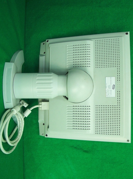
LCD Monitor - FCC ID PRXDAVI-1810A - Dataview Co., Ltd.
PRXDAVI-1810A

LCD Monitor

Jul 18, 2001

Equipment Class

JBP - Part 15 Class B Computing Device Peripheral