PS5CT2AL-Band Transceiver with GPS Reciever
BotCorp America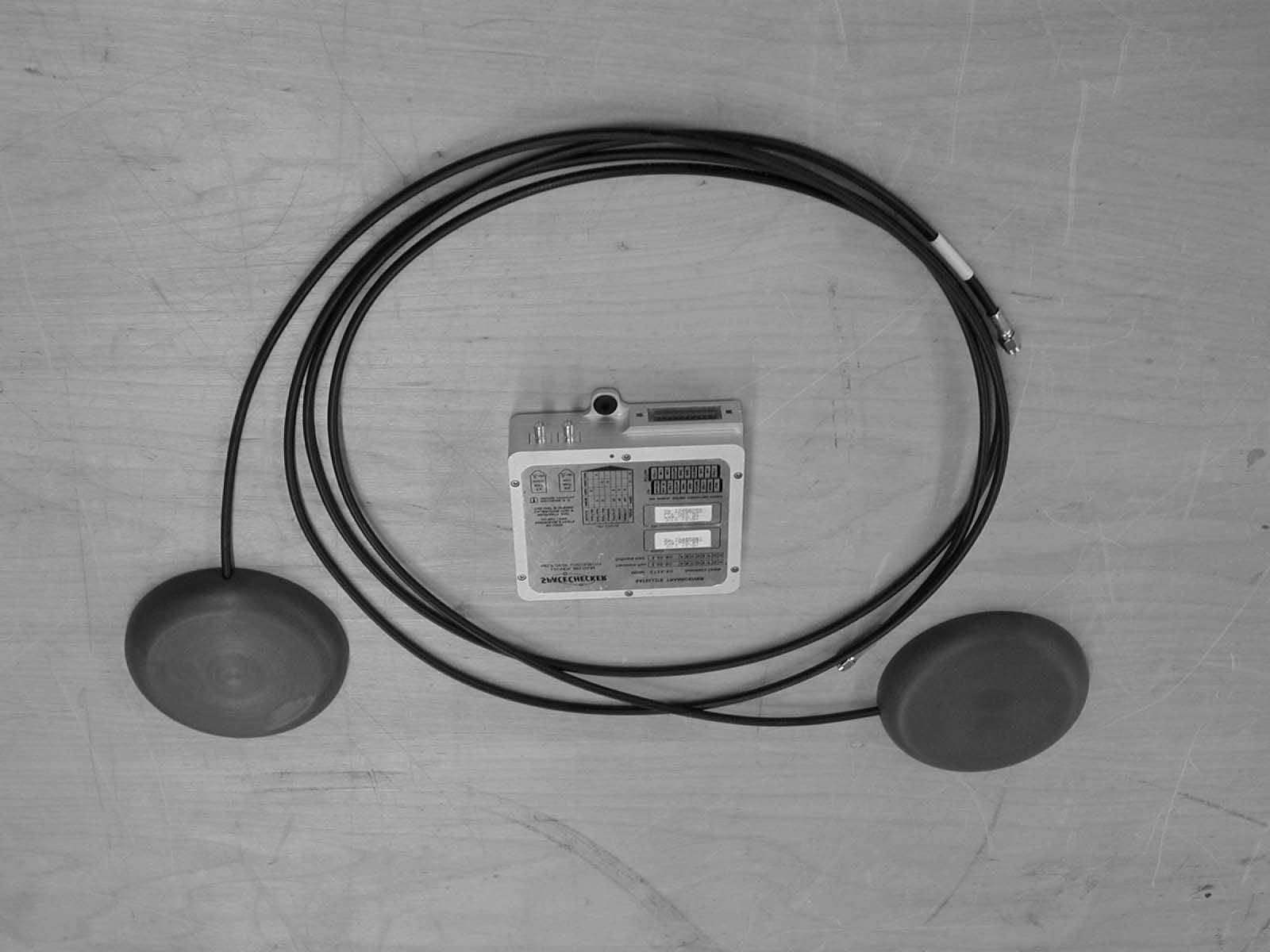
Click to zoom
Application Details
- Equipment Class
- TNB - Licensed Non-Broadcast Station Transmitter
- Date of Grant
- Jan 20, 2003
- Application Purpose
- Original Equipment
- Date of Application
- Nov 21, 2002
- Equipment Note
- L-Band Transceiver with GPS Reciever
- Frequency Range
- 1631.50000000 - 1660.50000000
- Company
- BotCorp America
- Country
- United States
Documents & Files
Document Text
Text extracted from the exhibit documents filed with the FCC. Open a document above to read the original.
Users Manual
BOTCORP AMERICA Release 1.0 June 12, 2001 Operational Manual for the Space-based Short Message System Terminal (SSMS) Model CT2A Operational ManualSpace-based Short Messaging System (SSMS)BOT-SSMS-CT2A CT2ARel. 1.0, 2001-Jun-12 PreliminaryCommercial ProprietaryControlled Circulation - Do Not Duplicate - i - Disclaimer Neither Botcorp America nor Mobilacomm (a division of Botcorp America) are responsible for the accuracy of the statements made or opinions expressed in this publication and neither Botcorp America nor Mobilacomm nor the author assumes liability with respect to any damages or loss incurred as a result of the use of the information contained in this publication. Neither Botcorp America nor Mobilacomm makes any representations in regards to the current licensing status of services using the SSMS terminal. For current information please consult the relevant licensing body. Copyright Notice This document contains proprietary intellectual property and confidential information. Dissemination of the information contained in this document to a Third Party, by whatever means and in whatever form, for example by copying, reproduction in any form, direct distribution of original documents, requires written approval from Botcorp America/Mobilacomm. Operational ManualSpace-based Short Messaging System (SSMS)BOT-SSMS-CT2A CT2ARel. 1.0, 2001-Jun-12 PreliminaryCommercial ProprietaryControlled Circulation - Do Not Duplicate - ii - Contacting the Manufacturer BotCor America/Mobilacomm Technical Support Address:775 Main Street, Suite # 230 Buffalo, New York, U.SA. 14203 Telephone:716 842 1033 Fax:76 842 1025 E-Mail:[email protected] Business Hours:Monday-Friday, 9:00 – 17:00 Eastern Standard Time Operational ManualSpace-based Short Messaging System (SSMS)BOT-SSMS-CT2A CT2ARel. 1.0, 2001-Jun-12 PreliminaryCommercial ProprietaryControlled Circulation - Do Not Duplicate - iii - Acknowledgments This document was prepared by BOTCORP America. 1. Prepared by: Chris Rampen Special Projects Bot Engineering Ltd. 2. Proofed by: Barbara Prescott Editor Bot Engineering Ltd. 3. Engineering Review by: Roger P. Bot Vice President Bot Engineering Ltd. 4. Approved by: David L. Bot President Bot Engineering Ltd. Distribution Document Issued by:C. RampenPurpose:Technical Support Distribution Media:Hard CopyRestrictions:Distribution List Only MS Word ’97 FilePositive Recall:No Originating Organization(s)Receiving Organization(s) BotCorp America General – NDA Required C. Rampen Operational ManualSpace-based Short Messaging System (SSMS)BOT-SSMS-CT2A CT2ARel. 1.0, 2001-Jun-12 PreliminaryCommercial ProprietaryControlled Circulation - Do Not Duplicate - iv - Document Release History ReleaseDateDescription 1.0 Draft-12000-Nov-19Preliminary Draft 1.0 Draft-22000-Dec-6Revised Draft 1.0 Draft-32001-Apr-2Revised Draft 1.0 Draft-42001-Apr-22Revised Draft 1.02001-Jun-12Release Operational ManualSpace-based Short Messaging System (SSMS)BOT-SSMS-CT2A CT2ARel. 1.0, 2001-Jun-12 PreliminaryCommercial ProprietaryControlled Circulation - Do Not Duplicate - v - Table of Contents 1SCOPE ................................................................................................................................................................ 1 1.1MODEL NOMENCLATURE .................................................................................................................... 1 2SSMS SYSTEM OVERVIEW ......................................................................................................................... 2 3TRANSCEIVER PHYSICAL CHARACTERISTICS .................................................................................... 4 3.1MODES OF OPERATION (TAMS) ........................................................................................................... 5 3.2SENSOR INPUTS ....................................................................................................................................... 6 3.3SSMS SYSTEM LIMITATIONS/WARNINGS ......................................................................................... 6 4CT-2A TERMINAL INSTALLATION AND TESTING ................................................................................ 7 4.1CT-2A TRANSCEIVER KIT CONTENTS .............................................................................................. 7 4.2BATTERY CONSIDERATIONS ............................................................................................................... 7 4.3ANTENNA MOUNTING AND INSTALLATION .................................................................................. 8 4.4TRANSCEIVER MOUNTING AND INSTALLATION ........................................................................ 8 4.5EXTERNAL SENSOR DESCRIPTION AND INSTALLATION ........................................................... 9 4.5.1Wiring Specifics ................................................................................................................................ 10 4.5.2Sensor Allocation to Return Link Message ....................................................................................... 11 4.6STEP BY STEP SYSTEM SETUP ........................................................................................................... 14 5TROUBLE SHOOTING .................................................................................................................................. 17 APPENDICES Appendix A:Specifications Operational ManualSpace-based Short Messaging System (SSMS)BOT-SSMS-CT2A CT2ARel. 1.0, 2001-Jun-12 PreliminaryCommercial ProprietaryControlled Circulation - Do Not Duplicate 1 SCOPE This document is intended to provide specific information required to install and operate the Space-based Short Message System (SSMS) Terminal (Model CT2A). Variations in SSMS functionality are dependant on the service subscribed to. This manual is intended to be as generic to all SSMS variants (Model CT-2A-(xxx)) as possible; for additional service sp…
Text truncated - open the document above for the full version.
Cover Letter(s)
LIST OF EXHIBITS The following exhibits comprise the submission for the L-band transceiver Model CT2A manufactured by BotCorp America /Mobilacomm: 1. Letter of Attestation 2. Confidentiality Request 3. Equipment ID Labels and locations 4. External and Internal (4A) Photographs 5. General Description 6. Circuit Diagrams (Schematics) 7. Circuit Descriptions 8. Type Approval Test Report 9. Antenna Test Report 10. RF Radiation Exposure Evaluation Report 11. Installation and Operation Manuals 12. Protection of GNSS (Amendment to Type Approval Test Report) 13. Parts List/Tune Up Info
Cover Letter(s)
CONFIDENTIALITY REQUEST November 20, 2002 To Whom It May Concern, Persuant 47CFR0.456(d)(1)(ii), it is understood that all material contained in this application be withheld from public inspection prior to the granting of a FCC license. BotCorp America/Mobilacom requests that certain material contained in this application be kept confidential after the grant is approved and is withheld from public inspection. It is understood that the FCC shall take measures to ensure that this material is securely kept and that circulation is controlled so that the documents are accessed only on a ‘need to know basis’ by appropriate FCC personnel. The material to be kept confidential comprises the following documents: • Internal Photographs • Circuit Diagrams • Circuit Descriptions • Antenna Type Approval Test Report • Parts Lists Specifically, these exhibits contain information that could be of significant financial and technical benefit to competitors and therefore is not to be released to the public. These exhibits contain trade secrets and commercial proprietary information that BotCorp America/Mobilacomm will not release for general circulation and is only releasing to the FCC for the purpose of the evaluation of our application for the authorization of our equipment. David Bot President, BotCorp America
Cover Letter(s)
Response to correspondence ref # 24582 Additional information and clarifications for the equipment authorization file FCC ID PS5CT2A Applicant: BotCorp America Correspondence Reference Number: 24582 731 Confirmation Number: EA192994 1) Part 25 with ERP>3W needs MPE test (not estimation), please submit. Alternatively, source-based time-averaging may apply without MPE test along with 2.1091(c) categorical exclusion if justified appropriately. For the satellite transceiver SSMS CT2A the source based time averaging may be applied as justified bellow, conform to FCC rule 2.1091 (c)(2) For the purpose of RF Radiation exposure estimation the most conservative case scenario is considered. The satellite transceiver SSMS CT2A operates in a time division multiple access mode (TDMA) and transmits an RF burst of maximum 1 second at a repetition interval of no less than 15 seconds. This leads to a maximum duty-cycle of 1/15. This case is limited by the inherent TDMA operational scheme, the design of the transmission control circuitry and the hardware design of the final amplifier section. Transmissions longer than 1 second , at intervals less than 15 seconds, lead to the final amplifier thermal overloading and self-destruction. It is noteworthy that the TDMA operational timing is a RF burst transmission of 80-millisecond transmission at intervals of no less than 15 seconds. The theoretical 15-second limit is imposed by the transmission control circuitry. Nominal operational transmission intervals are longer, typically 15 minutes intervals. Nevertheless, for the purpose of a conservative RF radiation exposure estimation an absolute theoretical worse case scenario bounded by the design of the TDMA transmission control circuitry and physical capabilities of the hardware has been considered. This is the 1/15 duty- cycle factor (an RF burst transmission of maximum 1 second at a repetition interval on no less than 15 seconds) According to FCC rule section 2.1091 (c)(2) “source-based” time-averaging based on an inherent property or duty cycle of a device is allowed. The “RF Radiation Exposure Evaluation Report for the SSMS Transceiver Model SSMS CT2A”, Exhibit 10, follows the analysis method and the exposure limits specified in FCC rule section 1.1310 and the procedures specified in the FCC OET Bulletin 65, “Evaluating Compliance with FCC Specified Guidelines for Human Exposure to Radiofrequency Radiation”. Exhibit 10 states that the satellite transceiver SSMS model CT2A complies with the limit specified in FCC rule section 1.1310 of 1 mW/cm 2 for general population averaged over a period of 30 minutes , for devices transmitting at frequencies above 1500 MHz. Exhibit 10 justifies the selection of the MPE method and the source based time averaging based on a duty cycle transmission rate of maximum 1/15. 2) Op desc exhibit states 34dBm+1dB=3.16W, Form 731 has 2.5W, MPE exhibit has 3.2W. Please clarify requested grant power, and repeat/clarify all tests/exhibits at max power if needed. The maximum power transmitted by the satellite transceiver SSMS CT2A at the antenna terminals is 35dBm = 3.16W. In the MPE exhibit the 3.16W value has been conservatively rounded off to a single decimal value of 3.2W. The maximum radiated power by the satellite transceiver SSMS CT2A is 12.5 dBW considering the maximum transmit antenna gain of 7.5 dBi. The form 713 should be amended to reflect the above-mentioned values. By a regrettable error the nominal power level of 2.5 W (34dBm) has been filled, instead of the maximum transmitted power at the antenna of 3.16 W (35dBm). The requested grant power should be 3.16W = 35dBm. All test results and exhibits are based on a specification of the maximum transmitted power at the antenna terminals of 35 dBm = 3.16W (rounded off to single decimal value of 3.2W for conservative computation in the MPE exhibit). Section 2.6 “Operating Power value” in Exhibit 8 (page 2.2) has been amended to correct the previously specified value and to add the maximum transmitted power value of 3.16W. Section 2.2 “FCC identifier” has also been amended to reflect the correct FCC Identifier. The amended Exhibit 8, revision 1.3 / Dec 20, 2002 has been resubmitted to the authorization file. Cornel Gazdaru BotCorp Mobilacomm. Dec 20, 2002
Cover Letter(s)
Response to correspondence ref # 24583 Additional information and clarifications for the equipment authorization file FCC ID PS5CT2A Applicant: BotCorp America Correspondence Reference Number: 24583 731 Confirmation Number: EA192994 Please provide the Part 25 rule section that allows operation in the 1631.5 - 1660.5 band The FCC rule in part 25, section 25.216 specifies the operation of METs with uplink frequencies in the band 1610 MHz to 1660.5 MHz. Section 25.216 has been added by FCC 02-134 report and order, which amends part 25 of the FCC rules, adopted on May 2, 2002 and released on May 14, 2002. A copy of the Appendix A of the above mentioned report and order, that amends part 25 has been appended to this letter. Exhibit 11 “GNSS Compliance” on file, submitted along with form 731 for equipment authorization, demonstrates the compliance of the satellite transceiver SSMS CT2A with the amended part 25 rules, section 25.216. Appendix B of the above mentioned FCC report and order contains the proposed rule change that specifies the mandatory equipment authorization before January 1, 2005 (operating in the band 1610 to 1660.5 MHz) pursuant to the certification procedures prescribed in Part 2, Subpart J, of the Commission rules [proposed amendments to section 25.216]. Cornel Gazdaru BotCorp Mobilacomm. Dec 20, 2002 ....................................................................................................... APPENDIX A 3 Rule Changes Title 47 of the Code of Federal Regulations, Part 25, is amended as follows: 1. The authority citation for Part 25 continues to read as follows: Authority: Sections 25.101 to 25.601 issued under Section 4, 48 Stat. 1066, as amended; 47 U.S.C. 154. Interpret or apply Sections 101-104, 76 Stat. 419-427; 47 U.S.C. 701-744; 47 U.S.C. 554. 2. Section 25.213 is amended by deleting Paragraph (b). 3. Section 25.200 is deleted. 4. A new section 25.216 is added and reads as follows: Section 25.216 Limits on Emissions from Mobile Earth Stations for Protection of Aeronautical Radionavigation-Satellite Service (a) The e.i.r.p. density of emissions from mobile earth stations placed in service on or before July 21, 2002 with assigned uplink frequencies between 1610 MHz and 1660.5 MHz shall not exceed -70 dBW/MHz, averaged over any 20 millisecond interval, in the band 1559-1587.42 MHz. The e.i.r.p. of discrete emissions of less than 700 Hz bandwidth generated by such stations shall not exceed -80 dBW, averaged over 20 milliseconds, in that band. (b) The e.i.r.p. density of emissions from mobile earth stations placed in service on or before July 21, 2002 with assigned uplink frequencies between 1610 MHz and 1626.5 MHz shall not exceed -64 dBW/MHz, averaged over 20 milliseconds, in the 1587.42-1605 MHz band. The e.i.r.p. of discrete emissions of less than 700 Hz bandwidth generated by such stations shall not exceed -74 dBW, averaged over 20 milliseconds, in the 1587.42-1605 MHz band. (c) The e.i.r.p. density of emissions from mobile earth stations placed in service after July 21, 2002 with assigned uplink frequencies between 1610 MHz and 1660.5 MHz shall not exceed -70 dBW/MHz, averaged over 20 milliseconds, in the 1559-1605 MHz band. The e.i.r.p. of discrete emissions of less than 700 Hz bandwidth from such stations shall not exceed -80 dBW, averaged over 20 milliseconds, in the 1559-1605 MHz band. (d) As of January 1, 2005 and from then on, the e.i.r.p. density of emissions from mobile earth stations placed in service on or before July 21, 2002 with assigned uplink frequencies between 1610 MHz and 1660.5 MHz (except Standard A Inmarsat terminals used as Global Maritime Distress and Safety System ship earth stations) shall not exceed -70 dBW/MHz, averaged over 20 milliseconds, in the 1559-1605 MHz band or a level in the 1605-1610 MHz band determined by linear interpolation from –70 dBW/MHz at 1605 MHz to –10 dBW/MHz at 1610 MHz, and the e.i.r.p. of discrete emissions of less than 700 Hz bandwidth from such stations shall not exceed -80 dBW, averaged over 20 milliseconds, in the 1559-1605 MHz band. (e) The e.i.r.p. density of emissions from mobile earth stations with assigned uplink frequencies between 1990 MHz and 2025 MHz shall not exceed -70 dBW/MHz, averaged over 20 milliseconds, in frequencies between 1559 MHz and 1610 MHz. The e.i.r.p. of discrete emissions of less than 700 Hz bandwidth from such stations shall not exceed -80 dBW, averaged over 20 milliseconds, in frequencies between 1559 MHz and 1605 MHz. (f) M M o o b b i i l l e e e e a a r r t t h h s s t t a a t t i i o o n n s s p p l l a a c c e e d d i i n n s s e e r r v v i i c c e e a a f f t t e e r r J J u u l l y y 2 2 1 1 , , 2 2 0 0 0 0 2 2 w w i i t t h h a a s s s s i i g g n n e e d d u u p p l l i i n n k k f f r r e e q q u u e e n n c c i i e e s s i i n n t t h h e e 1 1 6 6 1 1 0 0 - - 1 1 6 6 6 6 0 0 . . 5 5 M M H H z z b b a a n n d d s s h h a a l l l l s s u u p p p p r r e e s s s s t t h h e e p p o o w w e e r r d d e e n n s s i i t t y y o o f f e e m m i i s s s s i i o o n n s s i i n n t t h h e e 1 1 6 6 0 0 5 5 - - 1 1 6 6 1 1 0 0 M M H H z z b b a a n n d d t t o o a a n n e e x x t t e e n n t t d d e e t t e e r r m m i i n n e e d d b b y y l l i i n n e e a a r r i i n n t t e e r r p p o o l l a a t t i i o o n n f f r r o o m m - - 7 7 0 0 d d B B W W / / M M H H z z a a t t 1 1 6 6 0 0 5 5 M M H H z z t t o o - - 1 1 0 0 d d B B W W / / M M H H z z a a t t 1 1 6 6 1 1 0 0 M M H H z z . . N N O O T T E E : : O O p p e e r r a a t t i i o o n n o o f f m m o o b b i i l l e e e e a a r r t t h h s s t t a a t t i i o o n n s s i i s s a a l l s s o o s s u u b b j j e e c c t t t t o o a a l l l l p p e e r r t t i i n n e e n n t t e e m m i i s s s s i i o o n n s s l l i i m m i i t t s s s s p p e e c c i i f f i i e e d d i i n n o o t t h h e e r r s s e e c c t t i i o o n n s s o o f f t t h h e e C C o o m m m m i i s s s s i i o o n n ’ ’ s s R R u u l l e e …
Text truncated - open the document above for the full version.
Cover Letter(s)
Dear Mr. Dayhoff, In response to your correspondence (Your Reference No. 24680) please find attached a revised version of the equipment ID label. As you may be aware, this application is essentially a resubmission of a previous application in response to changes in FCC regulations. There appears to be some confusion regarding Exhibit 8. According to my files this should apply to the Technical Report for ‘Technical Report, Type Approval Procedures and Test Report for the SSMS Transceiver Model CT2A’, Release 1.3, December 20, 2002. This report has been revised and is in the FCC database. The user manual (Release 1, 2001 June 12 ) does not require revision at this time and can be considered as current. Best Regards, Chris Rampen BotCorp America
ID Label/Location Info
BotCorp TF NrQA Ref. TCF-SSMS-050401II01D Release 1 May 4, 2001 Exhibit 3: Equipment Identification and labelling of the S-SMS/CT1A-SC L-band Transceiver Circuit DiagramsSSMS-CT2AFCC-CircuitDiagrams-CT2A (FCC Qualification)Release 1 , 2001-May-04 CONFIDENTIALCommercial Proprietary Controlled Circulation - Do Not Duplicate - i - Disclaimer BotCorp nor the author assumes liability with respect to any damages or loss incurred as a result of the use of the information contained in this publication. Copyright Notice This document contains proprietary intellectual property and/or confidential information. It has been prepared by BotCorp and is provided for regulatory/licensing purposes. Dissemination of the information contained in this document to a Third Party, by whatever means and in whatever form, for example by copying, reproduction in any form, direct distribution of original documents, requires written approval by BotCorp. Circuit DiagramsSSMS-CT2AFCC-CircuitDiagrams-CT2A (FCC Qualification)Release 1 , 2001-May-04 CONFIDENTIALCommercial Proprietary Controlled Circulation - Do Not Duplicate - ii - Contacting the Manufacturer BOTCORP Technical Support Address:775 Main Street, Suite #230 Buffalo, New York, U.S.A. 14203 Telephone:716 842-1033 Fax:716 842-1025 E-Mail:[email protected] Business Hours:Monday-Friday, 9:00 – 17:00 Circuit DiagramsSSMS-CT2AFCC-CircuitDiagrams-CT2A (FCC Qualification)Release 1 , 2001-May-04 CONFIDENTIALCommercial Proprietary Controlled Circulation - Do Not Duplicate - iii - Acknowledgments This document was prepared by BotCorp 1. Prepared by: Chris Rampen Special Projects BotCorp 2. Edited by: Barbara Prescott Editor BotCorp 3. Engineering Review by: David Bot President BotCorp Distribution Note: This distribution list is subject to change without notice. Document Issued by:Chris RampenPurpose:CE Authorization Distribution Media:Hard CopyRestrictions:Distribution List Only MPositive Recall:Yes Originating Organization(s)Receiving Organization(s) BotCorp David BotPresident BotCorp C. Rampen / B. PrescottQA Circuit DiagramsSSMS-CT2AFCC-CircuitDiagrams-CT2A (FCC Qualification)Release 1 , 2001-May-04 CONFIDENTIALCommercial Proprietary Controlled Circulation - Do Not Duplicate - iv - Document Release History ReleaseDateDescriptionOrg. 12001-May-4ReleasedBot Circuit DiagramsSSMS-CT2AFCC-CircuitDiagrams-CT2A (FCC Qualification)Release 1 , 2001-May-04 CONFIDENTIALCommercial Proprietary Controlled Circulation - Do Not Duplicate - v - Table of Contents 1SCOPE..............................................................................................................................................................1.1 2LABEL INFORMATION...............................................................................................................................2.2 3NOTES..............................................................................................................................................................3.4 APPENDICES Appendix A:Applicable Documents & References Appendix B:Acronyms & Glossary Circuit DiagramsSSMS-CT2AFCC-CircuitDiagrams-CT2A (FCC Qualification)Release 1 , 2001-May-04 CONFIDENTIALCommercial Proprietary Controlled Circulation - Do Not Duplicate - 1.1 - 1 SCOPE This document describes the method used to identify the SSMS CT2A L-band transceiver as manufactured by BotCorp as required for FCC Equipment Authorization. Included in this application is a description of label content, location and label material type. Circuit DiagramsSSMS-CT2AFCC-CircuitDiagrams-CT2A (FCC Qualification)Release 1 , 2001-May-04 CONFIDENTIALCommercial Proprietary Controlled Circulation - Do Not Duplicate - 2.2 - 2 LABEL INFORMATION All regulatory and configuration information is located on Mylar™ label located on the transceiver (Figure 1). The label is indelibly printed and is affixed with to the transceiver using a permanent adhesive. Figure 1 Circuit DiagramsSSMS-CT2AFCC-CircuitDiagrams-CT2A (FCC Qualification)Release 1 , 2001-May-04 CONFIDENTIALCommercial Proprietary Controlled Circulation - Do Not Duplicate - 3.3 - 3 NOTES None. Circuit DiagramsSSMS-CT2AFCC-CircuitDiagrams-CT2A (FCC Qualification)Release 1 , 2001-May-04 CONFIDENTIALCommercial Proprietary Controlled Circulation - Do Not Duplicate - A1 - Appendix A Applicable Documents & References 1 APPLICABLE DOCUMENTS DocumentReleaseDateTitle & Author/Publisher 2 REFERENCES DocumentReleaseDateTitle & Author/Publisher None. SpecificationsIRD-30P/AP DetectorBot Engineering Ltd. Rel. 1.0, 1999-Oct-21 Appendix B Acronyms & Glossary 1 ACRONYMS GPS- Global Positioning System MOB- Mobile Terminal (Transceiver) S-SMS- Space-based Short Messaging System TAMs- Track and Manage Service 2 GLOSSARY None
ID Label/Location Info
Equip ID. SSMS-CT2A FCC-EquipIDs-CT2A (FCC Qualification) Release 2 , 2002-Dec-10 CONFIDENTIAL Commercial Proprietary Controlled Circulation - Do Not Duplicate 1 LABEL INFORMATION All regulatory and configuration information is located on Mylar™ label located on the transceiver (Figure 1). The label is indelibly printed and is affixed with to the transceiver using a permanent adhesive. Figure 1
ID Label/Location Info
Equip ID. SSMS-CT2A FCC-EquipIDs-CT2A (FCC Qualification) Release 3, 2003-Jan-13 CONFIDENTIAL Commercial Proprietary Controlled Circulation - Do Not Duplicate 1 LABEL INFORMATION All regulatory and configuration information is located on Mylar™ label located on the transceiver (Figure 1). The label is indelibly printed and is affixed with to the transceiver using a permanent adhesive. Figure 1
Operational Description
BotCorp TF NrQA Ref. TCF-SSMS-050401II01D Release 1 May 4, 2001 Exhibit 5: General Description Of the S-SMS/CT2A L-band Transceiver General DescriptionSSMS-CT2AFCC-GenDescr-CT2A (FCC Qualification)Release 1 , 2001-May-04 CONFIDENTIALCommercial Proprietary Controlled Circulation - Do Not Duplicate - i - Disclaimer BotCorp nor the author assumes liability with respect to any damages or loss incurred as a result of the use of the information contained in this publication. Copyright Notice This document contains proprietary intellectual property and/or confidential information. It has been prepared by BotCorp and is provided for regulatory/licensing purposes. Dissemination of the information contained in this document to a Third Party, by whatever means and in whatever form, for example by copying, reproduction in any form, direct distribution of original documents, requires written approval by BotCorp. General DescriptionSSMS-CT2AFCC-GenDescr-CT2A (FCC Qualification)Release 1 , 2001-May-04 CONFIDENTIALCommercial Proprietary Controlled Circulation - Do Not Duplicate - ii - Contacting the Manufacturer BOTCORP Technical Support Address:775 Main Street, Suite #230 Buffalo, New York, U.S.A. 14203 Telephone:716 842-1033 Fax:716 842-1025 E-Mail:[email protected] Business Hours:Monday-Friday, 9:00 – 17:00 General DescriptionSSMS-CT2AFCC-GenDescr-CT2A (FCC Qualification)Release 1 , 2001-May-04 CONFIDENTIALCommercial Proprietary Controlled Circulation - Do Not Duplicate - iii - Acknowledgments This document was prepared by BotCorp 1. Prepared by: Chris Rampen Special Projects BotCorp 2. Edited by: Barbara Prescott Editor BotCorp 3. Engineering Review by: David Bot President BotCorp Distribution Note: This distribution list is subject to change without notice. Document Issued by:Chris RampenPurpose:CE Authorization Distribution Media:Hard CopyRestrictions:Distribution List Only MPositive Recall:Yes Originating Organization(s)Receiving Organization(s) BotCorp David BotPresident BotCorp C. Rampen / B. PrescottQA General DescriptionSSMS-CT2AFCC-GenDescr-CT2A (FCC Qualification)Release 1 , 2001-May-04 CONFIDENTIALCommercial Proprietary Controlled Circulation - Do Not Duplicate - iv - Document Release History ReleaseDateDescriptionOrg. 12001-May-4ReleasedBot General DescriptionSSMS-CT2AFCC-GenDescr-CT2A (FCC Qualification)Release 1 , 2001-May-04 CONFIDENTIALCommercial Proprietary Controlled Circulation - Do Not Duplicate - v - Table of Contents 1SCOPE.............................................................................................................................................................1.1 2PRODUCT DESCRIPTION..........................................................................................................................2.2 3NOTES.............................................................................................................................................................3.1 APPENDICES Appendix A:Applicable Documents & References Appendix B:Acronyms & Glossary General DescriptionSSMS-CT2AFCC-GenDescr-CT2A (FCC Qualification)Release 1 , 2001-May-04 CONFIDENTIALCommercial Proprietary Controlled Circulation - Do Not Duplicate - 1.1 - 1 SCOPE This document is intended to describe to provide a general description of the S-SMS L-band transceiver Type S-SMS Model CT2A as manufactured by BotCorp as required for FCC Equipment Certification. General DescriptionSSMS-CT2AFCC-GenDescr-CT2A (FCC Qualification)Release 1 , 2001-May-04 CONFIDENTIALCommercial Proprietary Controlled Circulation - Do Not Duplicate - 2.2 - 2 PRODUCT DESCRIPTION The mobile terminals will be used to provide two-way data services to mobile platforms. A mobile terminal consists of receive and transmit antennas and a radio transceiver unit (Figure 1) to which sensors may be attached. The terminals use low-cost omni-directional antennas. The receive antenna is an active antenna, while the transmit antenna is of a passive type. The antennas are connected to the terminal via SMA connector ports. Figure 1 The terminal is powered from a DC voltage source with a nominal value of 12V. The power supply range is between 10V (minimum) and 18V (maximum). The terminals are designed to operate over a network conforming to the Satellite Short Messaging System (S-SMS) protocols. GPS location is used to provide real-time location of the each terminal. Each terminal also has a unique ID that is transmitted as part of the transmit protocol. These two features allow the Network Operational Centre (NOC) to locate individual terminals at any given time. The S-SMS terminals are full duplex terminals. The terminal design is such that the terminal is capable of transmitting while simultaneously receiving a ‘cease transmission’ command. When the terminal receives a cease transmission command or the TDM signal is cut, transmission is pre-empted. General DescriptionSSMS-CT2AFCC-GenDescr-CT2A (FCC Qualification)Release 1 , 2001-May-04 CONFIDENTIALCommercial Proprietary Controlled Circulation - Do Not Duplicate - 2.3 - Each mobile terminal is tuned to a channel which uses Time Division Multiplexing (TDM) to communicate with the mobile terminals. This channel originates at the NOC. A mobile terminal will not be allowed to transmit unless it is properly receiving the TDM channel. The mobile terminal will receive information over the TDM channel about the state of the network, access channel centre frequency for transmitting, and other informati…
Text truncated - open the document above for the full version.
Contact Information
Applicant
Chris F Rampen(Special Projects)
Technical Specifications
| # | Rule Parts | Frequency Range | Power Output | Emission | Tolerance |
|---|---|---|---|---|---|
| 1 | 25 | 1.63 GHz - 1.66 GHz | 2.5 W | 5K40G7D | 320.0000000000 Hz |