PSSNP130WNP130 Transmitter
Code 3, Inc.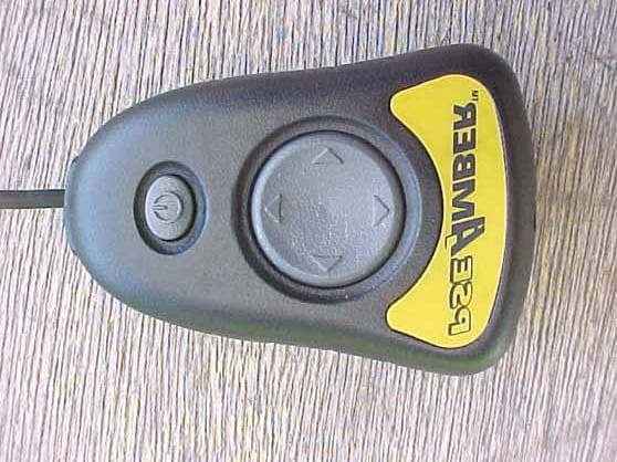
Click to zoom
Application Details
- Equipment Class
- DSC - Part 15 Security/Remote Control Transmitter
- Date of Grant
- Aug 20, 2001
- Application Purpose
- Original Equipment
- Date of Application
- Aug 20, 2001
- Equipment Note
- NP130 Transmitter
- Frequency Range
- 418.00000000 - 418.00000000
- Company
- Code 3, Inc.
- Country
- United States
Documents & Files
Document Text
Text extracted from the exhibit documents filed with the FCC. Open a document above to read the original.
Users Manual
INSTALLATION &OPERATION MANUAL NIGHTPROBE PATENT PENDING Read all instructions and warnings before installing and using. INSTALLER: This manual must be delivered to the end user of this equipment. IMPORTANT: TANT: NP 130 NIGHTPROBE Contents: Introduction (with warnings)................................ 2 Unpacking & Pre-Installation .............................. 2 Installation & Mounting ....................................... 2 Controller Installation................................................3 Wiring Instructions ............................................ 3 Maintenance....................................................... 4 Parts List (Replacement Parts/Exploded View) 5,6 Troubleshooting.........................................................7 Specifications ..................................................... 7 Warranty............................................................. 8 REMOTE CONTROLLED SPOTLIGHT REMOTE CONTROLLED SPOTLIGHT 2 The use of this or any warning device does not insure that all drivers can or will observe or react to an emergency warning signal. Never take the right-of-way for granted. It is your responsibility to be sure you can proceed safely before entering an intersection, driving against traffic, responding at a high rate of speed, or walking on or around traffic lanes. The effectiveness of this warning device is highly dependent upon correct mounting and wiring. Read and follow the manufacturerís instructions before installing or using this device. The vehicle operator should insure daily that all features of the device operate correctly. In use, the vehicle operator should insure the projection of the warning signal is not blocked by vehicle components (i.e.: open trunks or compartment doors), people, vehicles, or other obstructions. This equipment is intended for use by authorized personnel only. It is the userís responsibil- ity to understand and obey all laws regarding emergency warning devices. The user should check all applicable city, state and federal laws and regulations. Code 3, assumes no liability for any loss resulting from the use of this warning device. Introduction The NightProbe , NP 130, product is a remote control spotlight that delivers more signal power and versatility than any other spotlight product. Its low profile aerodynamic lines reduce air drag, which results in fuel savings and stability at high speeds. This product is made of shock-resistant high-temperature engineering thermoplastics and provides a warning signal that exceeds SAE standards. The NightProbe and its mounting system is designed to operate in many different locations including on the driver side, passenger side or center of the automobile hood rear lip. Unpacking & Pre-installation Remove the spotlight from the box and examine the unit for transit damage. Refer to parts list to insure that all parts are present for installation. Installation & Mounting 1. Attach suction cup to bottom of mounting bracket with the #10 self tapping screw, do not over tighten. 2. Route the cables from the bottom of the spotlight through the mounting bracket as shown in Figure 1. 3. Attach bracket to spotlight with four round hd phillips 6-20 x 3/8" SS as shown in Figure 1. 4. Choose a location where the spotlight is to be mounted. 5. Lay out the cable to insure that there is an adequate amount to reach the area in which the controller is to be mounted. 6. Fold wires into pocket of bracket in between the two mounting screws 7. Push bracket over lip of the hood and push down on suction cup 8. Tighten screws under hood until bracket is snug. WARNING! ! Vehicle Figure 1 For proper bracket alignment make sure that the mark is to rear of NightProbe as shown. 3 Connect the red and black wires from the NightProbe spotlight as shown in Figure 2. Protect the circuit with a 15 Amp fuse and use 14 awg (minimum) wire. Connect the white wire from the unit to an ignition switched circuit protected by a fuse (3 Amp Max.). Use a 22 awg. (minimum) wire. (see notes page 7) Failure to connect the wiring as stated above could cause damage to the unit. The NightProbe spotlight must never have its lamp on when its head is in the closed position (as shown in Figure 2). The extreme heat of the 100W lamp will damage the unit base. Wiring Instructions ! Route wiring using grommets and sealant when passing through compartment walls. High ambient temperatures (e.g. under-hood) will significantly reduce the current carrying capacity of wires, fuses, and circuit breakers. Use "SXL" type wire in engine compartment. Minimize the number of splices to reduce voltage drop. All wiring should conform to the minimum wire size and other recommendations of the manufacturer and be protected from moving parts and hot surfaces. Looms, grommets, cable ties, and similar installation hardware should be used to anchor and protect all wiring. Particular attention should be paid to the location and method of making electrical connections and splices to protect these points from corrosion and loss of conductivity. Ground terminations should only be made to substantial chassis components, preferably directly to the vehicle battery. The user should install a fuse sized to approximately 125% of the maximum amp capacity in the supply line and each switched circuit to protect against short circuits. WARNING! IMPORTANT: ! Any electronic device may create or be affected by electromagnetic interference. After installation of any electronic device, operate all equipment simultaneously to insure that operation is free of interference. WARNING! Figure 2 Figure 3 NP130 Cable Pendant Cable (Wired version only) PWM Jumper Connector Orientation PWM OFF PWM ON IMPORTANT: Make sure connector is in the correct orientation 4 The Night Probe controller provides a four-position switch for lighthead movement and a push-on/push-off switch for lamp control. The four-position switch provides either single-speed movement or Pulse Width Modulated (PWM…
Text truncated - open the document above for the full version.
Cover Letter(s)
REQUEST FOR TECHNICAL INFORMATION In order for processing of this application (FCC ID: PSSNP130W) to continue, the following issue(s) will have to be addressed: 1) In the test report (B10720D1), there is conflicting information. On pages 4 and 14, it states that the frequency range was investigated up to 3.2 GHz. On the data sheet in Appendix D, it states that the frequency range was investigated up to 4.2 GHz. Please provide a statement indicating the exact frequency range that was investigated. 2) The duty cycle plot states that the worst case duty cycle is 48%. A 48% duty cycle would cause the device to be in violation of the FCC rules by approximately 10 dB. On the data sheets in the test report (B10720D1), it states that the device has a 15% duty cycle. Please provide a statement that the duty cycle will not exceed 15%, and/or a plot of the actual worst case duty cycle. DO NOT REPLY TO THIS MESSAGE. PLEASE SEND RESPONSE TO: [email protected] and [email protected]. The item(s) indicated above must be submitted before processing can continue on the above referenced application. Failure to provide the requested information within 60 days of the original e-mail date may result in application dismissal and forfeiture of the filing fee. Also, please note that partial responses increase processing time and should not be submitted. Any questions about the content of this correspondence should be directed to [email protected]. If you have any questions, feel free to contact me. Best regards, Scott McCutchan Lab Manager Compatible Electronics, Brea Division (714) 579-1489 fax (714) 579-1850 http://www.celectronics.com RESPONSE >>> 1) In the test report (B10720D1), there is conflicting information. On pages 4 and 14, it states that the frequency range was investigated up to 3.2 GHz. On the data sheet in Appendix D, it states that the frequency range was investigated up to 4.2 GHz. Please provide a statement indicating the exact frequency range that was investigated. Response: The exact frequency range tested was up to 4.2 GHz as shown on the data sheet. The test report on pages 4 and 14 was NOT updated (forgot to change) to reflect this. The data sheet was made up right after the testing. Sorry about this. 2) The duty cycle plot states that the worst case duty cycle is 48%. A 48% duty cycle would cause the device to be in violation of the FCC rules by approximately 10 dB. On the data sheets in the test report (B10720D1), it states that the device has a 15% duty cycle. Please provide a statement that the duty cycle will not exceed 15%, and/or a plot of the actual worst case duty cycle. Response: Somehow the wrong duty cycle plot was sent. Attached will be the correct duty cycle plot showing that it is less than 15% (14.17%). The attachment is in *.PDF. Thank you, Kyle Fujimoto [email protected] Compatible Electronics -- Brea Division
Operational Description
2 The use of this or any warning device does not insure that all drivers can or will observe or react to an emergency warning signal. Never take the right-of-way for granted. It is your responsibility to be sure you can proceed safely before entering an intersection, driving against traffic, responding at a high rate of speed, or walking on or around traffic lanes. The effectiveness of this warning device is highly dependent upon correct mounting and wiring. Read and follow the manufacturerís instructions before installing or using this device. The vehicle operator should insure daily that all features of the device operate correctly. In use, the vehicle operator should insure the projection of the warning signal is not blocked by vehicle components (i.e.: open trunks or compartment doors), people, vehicles, or other obstructions. This equipment is intended for use by authorized personnel only. It is the userís responsibil- ity to understand and obey all laws regarding emergency warning devices. The user should check all applicable city, state and federal laws and regulations. Code 3, assumes no liability for any loss resulting from the use of this warning device. Introduction The NightProbe , NP 130, product is a remote control spotlight that delivers more signal power and versatility than any other spotlight product. Its low profile aerodynamic lines reduce air drag, which results in fuel savings and stability at high speeds. This product is made of shock-resistant high-temperature engineering thermoplastics and provides a warning signal that exceeds SAE standards. The NightProbe and its mounting system is designed to operate in many different locations including on the driver side, passenger side or center of the automobile hood rear lip. Unpacking & Pre-installation Remove the spotlight from the box and examine the unit for transit damage. Refer to parts list to insure that all parts are present for installation. Installation & Mounting 1. Attach suction cup to bottom of mounting bracket with the #10 self tapping screw, do not over tighten. 2. Route the cables from the bottom of the spotlight through the mounting bracket as shown in Figure 1. 3. Attach bracket to spotlight with four round hd phillips 6-20 x 3/8" SS as shown in Figure 1. 4. Choose a location where the spotlight is to be mounted. 5. Lay out the cable to insure that there is an adequate amount to reach the area in which the controller is to be mounted. 6. Fold wires into pocket of bracket in between the two mounting screws 7. Push bracket over lip of the hood and push down on suction cup 8. Tighten screws under hood until bracket is snug. WARNING! ! Vehicle Figure 1 For proper bracket alignment make sure that the mark is to rear of NightProbe as shown.
Test Report
FCC ID: PSSNP130W Report No.: B10720D1 114 OLINDA DRIVE, BREA, CALIFORNIA 92823 PHONE: (714) 579-0500 FAX: (714) 579-1850 Page 1 of 16 FCC PART 15, SUBPART C TEST METHOD: ANSI C63.4-1992 TEST REPORT for NP130 TRANSMITTER MODEL: S71612 Prepared for CODE 3, INC. 10986 NORTH WARSON ROAD ST. LOUIS MISSOURI, 63114-2029 Prepared by:_____________________ KYLE FUJIMOTO Approved by:____________________ MICHAEL CHRISTENSEN COMPATIBLE ELECTRONICS INC. 114 OLINDA DRIVE BREA, CALIFORNIA 92823 (714) 579-0500 DATE: JULY 27, 2001 REPORT APPENDICES TOTAL BODY A B C D E PAGES 16 2 2 10 12 2 44 This report shall not be reproduced except in full, without the written approval of Compatible Electronics. FCC ID: PSSNP130W Report No.: B10720D1 114 OLINDA DRIVE, BREA, CALIFORNIA 92823 PHONE: (714) 579-0500 FAX: (714) 579-1850 Page 2 of 16 TABLE OF CONTENTS Section / Title PAGE GENERAL REPORT SUMMARY 4 SUMMARY OF TEST RESULTS 4 1. PURPOSE 5 2. ADMINISTRATIVE DATA 6 2.1 Location of Testing 6 2.2 Traceability Statement 6 2.3 Cognizant Personnel 6 2.4 Date Test Sample was Received 6 2.5 Disposition of the Test Sample 6 2.6 Abbreviations and Acronyms 6 3. APPLICABLE DOCUMENTS 7 4. Description of Test Configuration 8 4.1 Description of Test Configuration - EMI 8 4.1.1 Cable Construction and Termination 9 5. LISTS OF EUT, ACCESSORIES AND TEST EQUIPMENT 10 5.1 EUT and Accessory List 10 5.2 EMI Test Equipment 11 6. TEST SITE DESCRIPTION 12 6.1 Test Facility Description 12 6.2 EUT Mounting, Bonding and Grounding 12 7. TEST PROCEDURES 13 7.1 Conducted Emissions Test 13 7.2 Radiated Emissions (Spurious and Harmonics) Test 14 7.3 Bandwidth of the Fundamental 15 8. CONCLUSIONS 16 FCC ID: PSSNP130W Report No.: B10720D1 114 OLINDA DRIVE, BREA, CALIFORNIA 92823 PHONE: (714) 579-0500 FAX: (714) 579-1850 Page 3 of 16 LIST OF APPENDICES APPENDIX TITLE A Modifications to the EUT B Additional Models Covered Under This Report C Diagrams, Charts and Photos • Test Setup Diagrams • Radiated Emissions Photos • Antenna and Effective Gain Factors D Data Sheets E Laboratory Recognitions LIST OF FIGURES FIGURE TITLE 1 Plot Map And Layout of Radiated Site FCC ID: PSSNP130W Report No.: B10720D1 114 OLINDA DRIVE, BREA, CALIFORNIA 92823 PHONE: (714) 579-0500 FAX: (714) 579-1850 Page 4 of 16 GENERAL REPORT SUMMARY This electromagnetic emission test report is generated by Compatible Electronics Inc., which is an independent testing and consulting firm. The test report is based on testing performed by Compatible Electronics personnel according to the measurement procedures described in the test specifications given below and in the "Test Procedures" section of this report. The measurement data and conclusions appearing herein relate only to the sample tested and this report may not be reproduced without the written permission of Compatible Electronics, unless done so in full. This report must not be used to claim product endorsement by NVLAP or any other agency of the U.S. Government. Device Tested: NP130 Transmitter Model: S71612 S/N: N/A Product Description: See Expository Statement. Modifications: The EUT was not modified during the testing. Manufacturer: Code 3, Inc. 10986 North Warson Road St. Louis, Missouri 63114-2029 Test Date: July 23, 2001 Test Specifications : EMI requirements CFR Title 47, Part 15 Subpart C, Sections 15.205, 15.209, and 15.231 Test Procedure: ANSI C63.4: 1992 Test Deviations: The test procedure was not deviated from during the testing. SUMMARY OF TEST RESULTS TEST DESCRIPTION RESULTS 1 Conducted RF Emissions, 450 kHz - 30 MHz This test was not performed because the EUT operates on batteries only and does not connect to the AC public mains. 2 Radiated RF Emissions, 10 kHz - 3200 MHz Complies with the limits of CFR Title 47, Part 15, Subpart C, sections 15.205, 15.209, and 15.231 FCC ID: PSSNP130W Report No.: B10720D1 114 OLINDA DRIVE, BREA, CALIFORNIA 92823 PHONE: (714) 579-0500 FAX: (714) 579-1850 Page 5 of 16 1. PURPOSE This document is a qualification test report based on the Electromagnetic Interference (EMI) tests performed on the NP130 Transmitter Model: S71612. The EMI measurements were performed according to the measurement procedure described in ANSI C63.4: 1992. The tests were performed in order to determine whether the electromagnetic emissions from the equipment under test, referred to as EUT hereafter, are within the specification limits defined by CFR Title 47, Part 15, Subpart C, sections 15.205, 15.209, and 15.231. FCC ID: PSSNP130W Report No.: B10720D1 114 OLINDA DRIVE, BREA, CALIFORNIA 92823 PHONE: (714) 579-0500 FAX: (714) 579-1850 Page 6 of 16 2. ADMINISTRATIVE DATA 2.1 Location of Testing The EMI tests described herein were performed at the test facility of Compatible Electronics, 114 Olinda Drive, Brea, California 92823. 2.2 Traceability Statement The calibration certificates of all test equipment used during the test are on file at the location of the test. The calibration is traceable to the National Institute of Standards and Technology (NIST) . 2.3 Cognizant Personnel Code 3, Inc. Robert E. Kreutzer Director of Engineering Roger Miller Electrical Design Engineer Compatible Electronics Inc. Kyle Fujimoto Test Engineer Michael Christensen Test Engineer 2.4 Date Test Sample was Received The test sample was received on July 20, 2001 2.5 Disposition of the Test Sample The test sample has not been returned to Code 3, Inc. as of July 27, 2001. 2.6 Abbreviations and Acronyms The following abbreviations and acronyms may be used in this document. RF Radio Frequency EMI Electromagnetic Interference EUT Equipment Under Test P/N Part Number S/N Serial Number HP Hewlett Packard ITE Information Technology Equipment CML Corrected Meter Limit LISN Line Impedance Stabilization Network FCC ID: PSSNP130W Report No.: B10720D1 114 OLINDA DRIVE, BREA, CALIFORNIA 92823 PHONE: (714) 579-0500 FAX: (714) 579-1850 Page 7 of 16 3. APPLICABLE DOCUMENTS The following documents are referenced or used in the preparation of this …
Text truncated - open the document above for the full version.
Test Report
PROPRIETARY AND CONFIDENTIAL INFORMATION 7/27/01 3:29 PM 1 …
Text truncated - open the document above for the full version.
Contact Information
Applicant
Roger Miller(Electrical Design Engineer)
[email protected](502)241-7332
Technical Contact
Compatible ElectronicsKyle Fujimoto
714-579-0500
114 Olinda Drive · Brea, California · United States
Test Firm
Compatible ElectronicsScott McCutchan
714-579-0500Fax: 714-579-1850
Technical Specifications
| # | Rule Parts | Frequency Range | Power Output |
|---|---|---|---|
| 1 | 15.231 | 418 MHz - 418 MHz | 100.00 µW |