PSTDF1000RCommunications Receiver
NorCross Marine Products, Inc.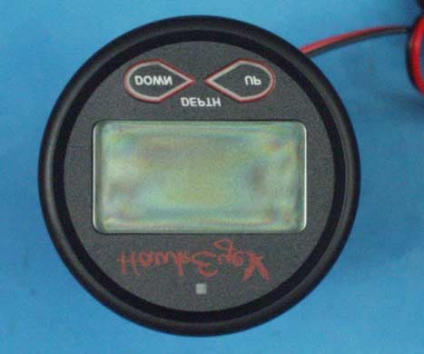
Click to zoom
Application Details
- Equipment Class
- CYY - Communications Receiver used w/Pt 15 Transmitter
- Date of Grant
- Sep 04, 2001
- Application Purpose
- Original Equipment
- Date of Application
- Sep 04, 2001
- Equipment Note
- Communications Receiver
- Frequency Range
- 903.00000000 - 927.00000000
- Country
- United States
Documents & Files

Document Text
Text extracted from the exhibit documents filed with the FCC. Open a document above to read the original.
Users Manual
ML100R ML100DR ML100TDR ML100TR 1629 Prime Court, Suite 800 Orlando, FL32809 PH: (407) 581-2614 Fax: (407) 422-0501 Toll Free: 888-NorCross Email: [email protected] 2001 NorCross Marine Products, Inc., All rights reserved. All Specifications are subject to change without notice. MANML100-05-01 2. Clean and dry both the selected area and the face of the transducer with a weak solvent to remove any dust, grease or oil. 3. If the hull temperature is above 15ºC (60ºF), mix the epoxy until the color is uniform. Do not proceed if the hull temperature is below 15ºC (60ºF) because the cure time will be greatly extended. 4. Apply a generous amount of epoxy to the center of the face of the transducer (side opposite from the cable). 5. Press the transducer face onto the hull with a twisting motion to expel all air bubbles. (If the hull is slanted, tem- porarily secure the transducer in place with duct tape.) The adhesive is cured in 24 hours at 21ºC (70ºF). The lower the temperature the longer the cure time. 6. After the adhesive has cured, route the cable to the transmitter being careful not to tear the cable jacket when passing it through the bulkhead and other parts of the boat. To reduce electrical interference, separate the transducer cable from other electrical wiring and sources of interference. To prevent damage, cut the transducer cable to the desired length. NOTE!!!! The working time of the epoxy is only 5 minutes. 36 FIGURE10C If the hull surface is not smooth, grind it with a disc sander. Partially fill a thin plastic bag with water, place the transducer inside and close it tightly with a tie wrap. Wet the surface of the hull and press the transducer face against it through the bag (Figure 20 C). Selecting the Adhesive Hard adhesives, transmit sound best, but winter tempera- ture extremes and flexing on trailer rollers can cause it to delaminate. However, soft adhesives absorb sound. To compromise, use a viscous slow-cure epoxy or a fairly rigid, one part adhesive sealant. In cold climates, a one- part polyurethane adhesive, such as Boat-Life’s Life Seal‚ may be best. Do not use “5 minute” epoxies because they are generally brittle. RTV (silicone) adhesives are not rec- ommended because most of the sound energy is lost. Installation 1. All surfaces to be bonded must be smooth, clean and dry. If the surface is rough, use a disk sander to smooth an area a little larger in diameter than the length of the transducer. CAUTION!!!! Always wear safety goggles and a dust mask when sanding. 35 TABLEOFCONTENTS Transducer Selection . . . . . . . . . . . . . . . . . . . . . . . . . . Transducer Installation . . . . . . . . . . . . . . . . . . . . . . . . Setting up the Transmitter and Receiver . . . . . . . . . . . Transmitter Installation (ML100T) . . . . . . . . . . . . . . . . Installing the In-Dash Wireless Display (ML100DR) . . . Installing the Portable Wireless Display (ML100R) . . . Operating the Transmitter (ML100T) . . . . . . . . . . . . . . Operating the Wireless Displays (ML100R, ML100DR) Warranty Information . . . . . . . . . . . . . . . . . . . . . . . . . . Specifications . . . . . . . . . . . . . . . . . . . . . . . . . . . . . . . Accessories . . . . . . . . . . . . . . . . . . . . . . . . . . . . . . . . . Troubleshooting . . . . . . . . . . . . . . . . . . . . . . . . . . . . . . In-Hull Transducer Installation (Appendix A) . . . . . . . . 4 5 5 7 10 13 14 15 20 22 23 24 28 ML100DRIn-Dash Wireless Display **Included within the ML100TDR System. Additional displays can be added at any time by following the setup instructions on page 5. ML100RPortable Wireless Display **Included within the ML100TR System. Additional Display can be added at any time by following the setup instructions on page 5. ML100TWireless Depth Sounder Transmitter **Included within the ML100TR and ML100DTR Systems. Both the ML100R and ML100DR wireless displays require the transmitter to function as a depth sounder display. Model Identification 2 FIGURE10A •This method is practical if the transducer will be located near the stern and the boat has a low deadrise angle. Clean away any large build-up of grease and / or dirt. Place the transducer against the hull and allow bilge water to cover the surface where they touch (see Figure 20 A). FIGURE10B • If the hull surface is not smooth, grind it with a disc sander. Coat the face of the transducer with petroleum jelly and press it against the hull with a twisting motion (see Figure 20 B). CAUTION!!!! Always wear safety goggles and a dust mask when sanding. Figure 20 A B C 343 Warning: Changes or modifications to this unit not expressly approved by the party responsible for com- pliance could void the user’s authority to operate the equipment. This device complies with part 15 of the FCC rules. Operation is subject to the following two conditions: 1) This device may not cause harmful interference and 2) This device must accept any interference received, including interference that may cause undesired operation. Testing the Depth Sounder Establish a performance baseline by operating the depth sounder with the transducer directly in the water.The results of this test are used as a basis of comparison to determine the best in-hull location for the transducer. 1. Anchor the boat in at least 15 m (50') of water. (If you have a digital unit, conduct this test in water as deep as that for which the depth sounder is rated.) 2. Tape the transducer to a pole, cable side up, and hold it over the side of the boat (Figure 19). The cable side must be parallel to the surface of the water. 3. Observe the depth sounder performance. Record the depth reading. Testing at the Selected Location While the boat is anchored, use one of the methods below to test the depth sounder with the transducer at the selected location. If the test readings differ markedly from the base- line or there is almost no reading, you will need to find anoth- er location. If the two readings are re…
Text truncated - open the document above for the full version.
External Photos
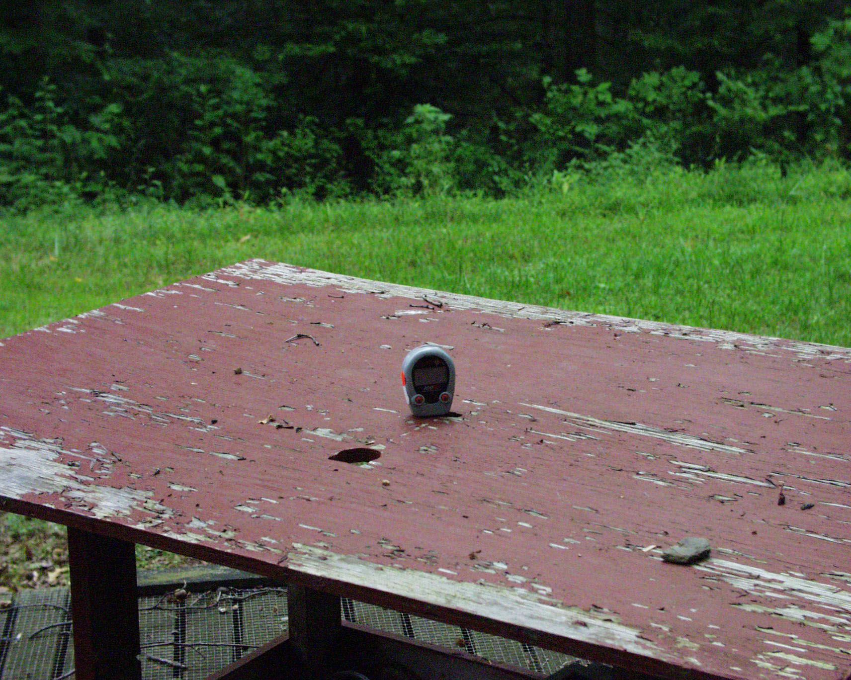
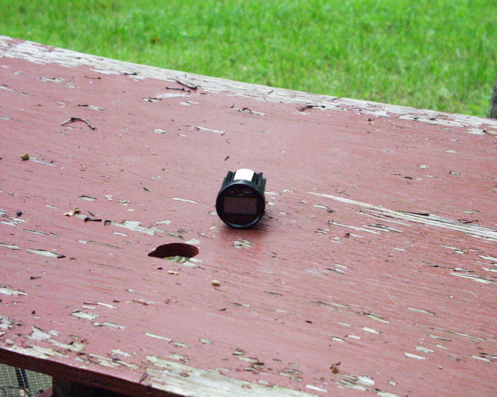
HAND-HELD RECEIVER Front View Back View Top View Bottom View Left Side View Right Side View PANEL MOUNT RECEIVER Exterior View Front View Rear View
Internal Photos
HAND HELD RECEIVER Inside Top Case Regulator Board – Track Side Regulator Board PANEL MOUNT RECEIVER DC Regulator Board Panel Mount Display Board Component Side Circuit Board Interior View COMMON RECEIVER BOARDS Common Receiver Board – Component Side Common Receiver Board – Circuit Side
Test Report
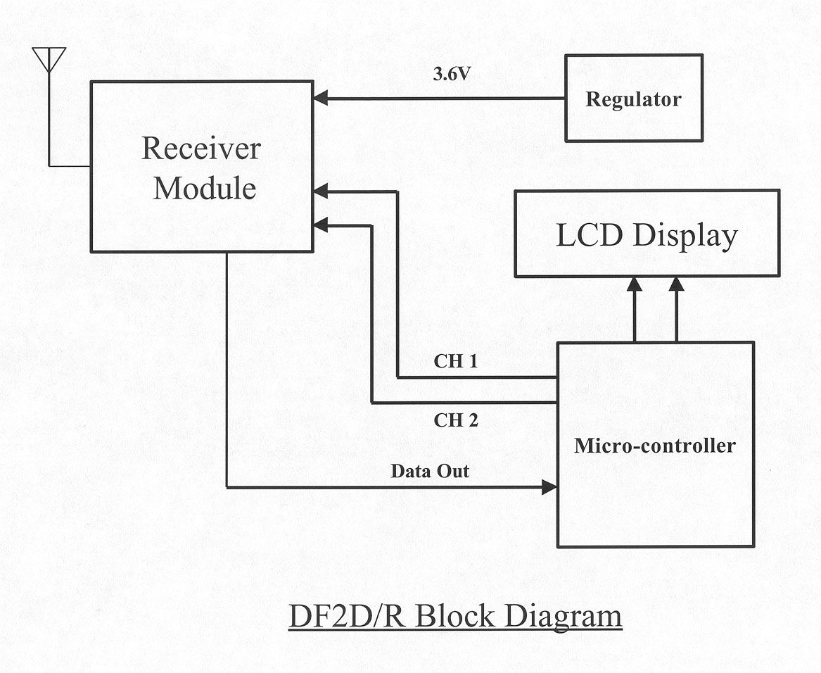
ENGINEERING STATEMENT In Regard to Measurements on NorCross Marine Products, Inc. MODEL: DF2D/DF2R FCC ID: PSTDF1000R A. INTRODUCTION Hyak Laboratories, Inc. has been authorized by NorCross Marine Products, Inc., to determine compliance with FCC rules, Part 15, Subpart B. The device operates in the 903 - 927 MHz band and is intended for use as a remote depth sounder display. 1. The receiver module receives RF signal sent from a DF20 transmitter, demodulates the RF signal and retrieves the digital data. 2. Two different case configurations are used. Both have the same receiver module board and internal antenna: DF2D: Panel mount, operates from vessel’s 12 V dc line. DF2R: Hand-Held, operates from Nicad batteries. 3. There are two channels to select from, channel selection is done by the micro-controller. The two crystals determine the receiving frequencies which equal to (F c +10.7) MHz. 4. The 2 crystals X1 and X2 can be selected by forward biased the diodes D1 and D2 respectively. The desired receiving can be trimmed by the trimmer capacitor. 5. The heart of the receiver module is a integrated receiver IC RF2917 by RF Micro Devices. The Local Oscillator is a PLL oscillator, its division is 64. The LO frequency is determined by 64 x frequency of the crystal selected. 6. RF at pin 2 is amplified and then mixed with LO frequency and down-converted to 10.7 MHz IF frequency. 7. There are two ceramic filters YL1 and YL2. These filters reject signals other than 10.7 MHz. 8. YL3 is a ceramic discriminator where FM demodulation is done. 9. Demodulated signal is at pin 22. 10. Signal at pin 21 is the Radio Signal Strength Indicator which indicates the signal strength. 11. No external antenna is used. B. DESCRIPTION OF DEVICE The device incorporates a super-heterodyne design. The following information is supplied as requested in FCC Bulletin OCE 24: 1. Service in which the device will be used: Part 15. 2. Function of device: Depth Sounder Display. 3. Tuning range: 903 - 927 MHz. 4. IF used: 10.7 MHz. 5. Fundamental frequency of principal oscillators in the device. First local oscillator: F c +10.7 MHz (PLL). 2 C. DESCRIPTION OF MEASUREMENT FACILITIES A description of the Hyak Laboratories' radiation test facility is a matter of record with the FCC. The facility was accepted for radiation measurements from 30 to 1000 MHz on October 1, 1976, and is currently listed as an accepted site. D. DESCRIPTION OF MEASUREMENT PROCEDURE: RADIATED EMISSIONS Measurements of radiated field strength were made using ANSI C63.4 (1992) as the basic procedure. Measurements were made with 3-meter spacing between the device under test and the test equipment antenna. The antenna(s) connected to the device under test consisted of a internal wire approximately 6 cm long. The device under test was placed on a rotatable table 80 cm in height. Measurement of field strength was made through use of Tektronix 494P spectrum analyzer in conjunction with Singer DM- 105A series or EMCO 3221 calibrated dipoles or EMCO 3115 DRG horn. For each spurious emission identified between 30 to 5500 MHz (per Para 15.33(b)(1)), the test sample was rotated for maximum pickup, the test antenna varied in elevation, and the test antenna polarization shifted between horizontal to vertical in order to maximize observed signals. E. REPORT OF RADIATED EMISSIONS 1. Table 1 lists the frequency and amplitude of all signals observed from 30 to 5500 MHz including those 20 dB below the limits of paragraph 15.109 of the FCC Rules. 3 TABLE 1a RADIATED SPURIOUS EMISSIONS Measured at 3 meters PART 15(B) PARA. 15.109 Frequency Frequency To Which of Meter Antenna Field 1 Tuned Emission Reading Factor Intensity FCC Limit dB to (MHz) (MHz) (dBm) (dB) uV/m @ 3m uV/m @ 3m Limit 903.530 891.699 -93.5 23.2 68.8 200 -9.3 922.950 912.252 -92.4 23.2 77.6 200 -8.2 927.000 916.269 -89.9 23.2 103.5 200 -5.7 Note 1: uV/m = Log -1dBu/m 20 dBu = dBm + antenna factor + 107 RADIATED SPURIOUS EMISSIONS FCC ID: PD4DF1000R TABLE 1a, DF2D (Panel Mount) 4 TABLE 1b RADIATED SPURIOUS EMISSIONS Measured at 3 meters PART 15(B) PARA. 15.109 Frequency Frequency To Which of Meter Antenna Field 1 Tuned Emission Reading Factor Intensity FCC Limit dB to (MHz) (MHz) (dBm) (dB) uV/m @ 3m uV/m @ 3m Limit 903.470 892.891 -95.5 23.2 54.3 200 -11.3 923.869 913.088 -94.9 23.2 58.2 200 -10.7 926.998 916.288 -91.1 23.2 90.2 200 - 6.9 Note 1: uV/m = Log -1dBu/m 20 dBu = dBm + antenna factor + 107 RADIATED SPURIOUS EMISSIONS FCC ID: PD4DF1000R TABLE 1b, DF2R (Hand-Held) 5 F. PROCEDURE - AC LINE CONDUCTED SPURIOUS The receiver does not operate from the AC line. G. STATEMENT Technical test data are from tests performed by me or under my supervision. My qualifications are a matter of record with the Federal Communications Commission. I personally attest to the accuracy of the test data submitted as a part of this engineering statement. __________________________________ Rowland S. Johnson Dated: July 20, 2001 6
Contact Information
Applicant
Greg Lentine(President)
Test Firm
Hyak Laboratories, Inc.Rowland Johnson
703-451-1188
Technical Specifications
| # | Rule Parts | Frequency Range | Power Output |
|---|---|---|---|
| 1 | 15B | 903 MHz - 927 MHz | - |
Other Applications from NorCross Marine Products, Inc.
PST-DT3BXTM
Jan 21, 2026Boat Mount Depth Finder
Equipment Class
DTS - Digital Transmission System
PSTDF1000T
Sep 04, 2001Depth Sounder
Equipment Class
DXX - Part 15 Low Power Communication Device Transmitter