PT9SDU-2000UHF Telemetry Transceiver
TecNet Global Corporation
Click to zoom
Application Details
- Equipment Class
- TNB - Licensed Non-Broadcast Station Transmitter
- Date of Grant
- Jan 16, 2002
- Application Purpose
- Original Equipment
- Date of Application
- Oct 07, 2001
- Equipment Note
- UHF Telemetry Transceiver
- Frequency Range
- 450.00000000 - 470.00000000
- Company
- TecNet Global Corporation
- Country
- United States
Documents & Files
Document Text
Text extracted from the exhibit documents filed with the FCC. Open a document above to read the original.
Cover Letter(s)
Timco Engineering Inc. 849 NW SR 45 Newberry FL 32669 page 1 Mario de Aranzeta Engineer Timco Engineering Inc. To: Andy Leimer Re: FCC ID PT9SDU-2000 Ref # 21335 731 Confirm #: EA102679 1) The BW plots do not appears to be for the maximum data rates. It is not clear as to what the 825 Hz tone represents. Submit new BW plots at the maximum data rates. The plot is marked in error. I’ve looked at the original plot in o ur records. It is marked (o n the reverse side) 9600 baud with an 825 Hz deviatio n (the peak deviatio n). This plot is identical to the plot on the next page but at a different center frequency. I’ve included a revised plot (labeled correctly) as page 5 of this note. 2) The calculations for Authorized BW (2M + 2D) were done with a peak deviation of 0.4 kHz for 25 kHz channel spacing and 0.825 kHz for 12.5 kHz channel spacing. Please explain why this was done. If the deviation is increased any higher it will exceed the allowed bandwidth as per the equatio n. The deviation is set at the factory based on the license of the final customer. I noticed a typographical error o n page 1 of the report in the calculatio n for the 25 kHz BW the 10.4 is incorrect and 0.4 is correct as in the information above the equatio n. A corrected page is enclosed as page 2 of this note. 3) Provide measurement details for radiated spurious emissions. Provide a sample calculation. The radiated spurio us emissio n page sho uld have a statement that the procedure used was the substitution method in TIA/EIA 603-.2.2.12. This line was inadvertently omitted from the page. These are dBc values (below the carrier). A corrected copy is enclosed as page 3. 4) The Tune-up Procedure says to set the power to 2 +- 0.05 Watts. The application is for 4.5 Watts conducted power. Explain this discrepancy. The SD2000 device is the same exact radio as a previo us product except for the change in o utput power from 2 watts to 4.5 watts which was do ne by changing the final RF semiconductor device.. The tune-up procedure submitted by the customer was for this previo us product and failed to reflect the change. A new page reflecting this change is included as page 4. Timco Engineering Inc. 849 NW SR 45 Newberry FL 32669 page 2 GENERAL_INFORMATION_REQUIRED FOR_TYPE_ACCEPTANCE 2.1033 TECNET GLOBAL CORPORATION will sell the (c)(1)(2) FCC ID: PT9SDU-2000 UHF transceiver in quantity, for use under FCC RULES PART 22 & 90. 2.1033 (c) TECHNICAL DESCRIPTION 2.1033 (3) User Manual See Exhibit 3 MODELS SDU-2000 AND TNET-44 SHARE THE SAME USERS MANUAL 2.1033 (4) Type of Emission: 20K0F2D For 25 kHz 10K0F2D For 12.5 kHz For 25 kHz Bn = 2M + 2DK M = 19,200Bits per second D = 0.4 kHz (Peak Deviation) K = 1 Bn = 2(19,200/2) + 2(0.4k)(1) = 19.2k + 0.8k = 20.0K ALLOWED AUTHORIZED BANDWIDTH = 20.00 kHz. For 12.5 kHz Bn = 2M +2DK M = 9600Bits per second D = 0.825 kHz (Peak Deviation) K = 1 Bn = 2(9.6/2) K + 2(0.825k)(1) = 9.6k = 1.65k = 11.25 k ALLOWED AUTHORIZED BANDWIDTH = 11.25 kHz. 90.209(b)(5) 2.1033 (5) Frequency Range: 450-470 MHz (6) Power Range and Controls:There are NO user Power controls. (7) Maximum Output Power Rating: 4.5 Watts , into a 50 ohm resistive load. (8) DC Voltages and Current into Final Amplifier: POWER INPUT FINAL AMPLIFIER ONLY Vce = 13.6 Volts IC = 1.2A Pin = 16.3 Watts Efficiency = 27.6% Timco Engineering Inc. 849 NW SR 45 Newberry FL 32669 page 3 2.1053 Field strength of spurious emissions: NAME OF TEST: RADIATED SPURIOUS EMISSIONS REQUIREMENTS: Emissions must be 50 +10log(Po) dB below the mean power output of the transmitter. 50 + 10log(4.5) = 56.50dB TEST DATA: Emission Frequency MHz Ant. Polarity Attn. dBc Margin dB 460.10 H 0.00 0.00 920.20 H 55.93 0.25 1,380.30 v 69.76 14.08 1,840.50 v 81.63 25.95 2,300.60 v 75.55 19.87 2,760.70 h 96.87 41.19 3,220.80 v 84.20 28.52 3,681.00 v 93.50 37.82 4,141.10 v 79.38 23.70 4,601.20 h 91.65 35.97 METHOD OF MEASUREMENT: The tabulated Data shows the results of the radiated field strength emissions and attenuation calculated per TIA/EIA 603. The spectrum was scanned from 30 to at least the tenth harmonic of the fundamental. This test was conducted per TIA/EIA 603- 2.2.12 (substitution method). Measurements were made at the open field test site of TIMCO ENGINEERING INC. located at 849 N.W. STATE ROAD 45, NEWBERRY, FL 32669. Timco Engineering Inc. 849 NW SR 45 Newberry FL 32669 page 4 Timco Engineering Inc. 849 NW SR 45 Newberry FL 32669 page 5
Cover Letter(s)
Timco Engineering Inc. 849 NW SR 45 Newberry FL 32669 page 1 Mario de Aranzeta Engineer Timco Engineering Inc. To: Andy Leimer email: [email protected] Re: FCC ID PT9SDU-2000 Ref # 21490 731 Confirm #: EA102679 1) Explain why their is an identical application Granted under FCC ID: PT9SDU-7000 (TC694638). 1) Originally the applicant was offered to submit this job to a TCB. But the questio n of use in a fixed and/ or mobile applicatio n came up (a TCB only being able to approve a fixed mounted product in this power range). The users manual originally reflects a fixed mo unting for submission to a TCB. The applicant then asked us to not submit it for TCB approval for this reason. Unfortunately, the users manual was not updated to reflect this. Later, the applicant having a customer who wanted a fixed mounted product and seeing a shorter time to market for this customer, changed the FCC ID and asked for approval of a fixed mounted device. The applicant applied for a TCB grant with this stipulatio n on the grant and in the users manual (same as sent to FCC). Attached is page 3 of the users manual that sho uld have been sent with the FCC submission. The applicant wo uld still like an FCC approval for the SD2000 product so their customers may obtain fixed and mobile licenses using this product. Thanks, Mario de Aranzeta Timco Engineering Inc. 849 NW SR 45 Newberry FL 32669 page 2
Cover Letter(s)
page 1 Mario de Aranzeta Timco Engineering Inc. 849 NW SR 45 Newberry FL 32669 Andy Leimer [email protected] FCC Application Processing Branch Re: FCC ID PT9SDU-2000 Applicant: TecNet Global Corporation Correspondence Reference Number: 21594 731 Confirmation Number: EA102679 Andy you have received the updated SDU-2000 product users manual page in my last note. It is marked exhibit 3 and was page two of my last note (I’ve included it again as page 4). I have excerpted both RF exposure statements and included the exposure statements from BOTH users manuals here (page 3). As to antenna specifications, I am under the understanding that at the time TecNet Global’s customer obtains their license to use this radio, compliance with RF exposure will be addressed and that the manufacturer of the radio does not have to address the antenna issue. TecNet Global supplies only the radio and not an entire system to the customer. I am submitting a MPE calculation based on a worst case installation of this radio. Sincerely, Mario de Aranzeta page 2 W4.50 power in Watts D1 Duty Factor in decimal % (1=100%) E1.2 exposure time in minutes U6 (use 6 for controlled and 30 for uncontrolled) WexpW D . E U . PC E U PC0.2 = percent on time Wexp0.9 = Watts Correction for ON Time in 6 Minutes Po900mWattsdBd5 antenna gain f460 Frequency in MHz GdBd2.15 gain in dBi gain numeric S f 300 1500 use for uncontrolled exposure Gn10 G 10 use 300 for controlled Gn5.188 = S1.533 = R Po Gn . () 4 π . S . () inches R 2.54 R15.567 = distance in centimeters required for compliance inches6.129 = RF Exposure Assessment page 3 Note: This device is a low power transmitter. In August of 1996, the Federal Communications Commission (FCC) adopted RF exposure guidelines with safety levels for wireless devices. End users must ensure compliance with RF exposure guidelines at the time of licensing. This is the statement in the SD2000 users manual. Note: The antenna(s) used for this transmitter must be fixed- mounted on outside permanent structures. End users must ensure compliance with RF exposure guidelines at the time of licensing. This is the statement in the SD7000 users manual. page 4
ID Label/Location Info
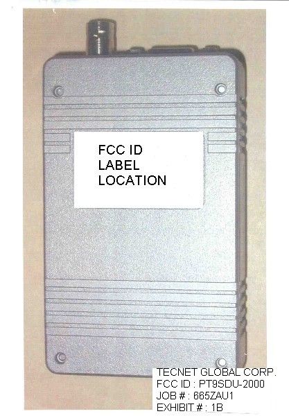
TecNET TecNETTecNET TecNET TecNET GLOBAL TecNET GLOBALTecNET GLOBAL TecNET GLOBAL CORPORATION CORPORATIONCORPORATION CORPORATION MODEL NO. SDU-2000 FCC ID : PT9SDU-2000 CANADA # : THIS DEVICE COMPLIES WITH PART 15 OF THE FCC RULES OPERATION IS SUBJECT TO THE CONDITION THAT THIS DEVICE DOES NOT CAUSE HARMFUL INTERFERENCE. TECNET GLOBAL CORP. FCC ID : PT9SDU-2000 JOB # : 665ZAU1 EXHIBIT # : 1
ID Label/Location Info
TecNETTecNET TecNET GLOBAL CORPORATIONTecNET GLOBAL CORPORATION MODEL NO. SDU-2000 FCC ID : PT9SDU-2000 CANADA # : THIS DEVICE COMPLIES WITH PART 15 OF THE FCC RULES OPERATION IS SUBJECT TO THE CONDITION THAT THIS DEVICE DOES NOT CAUSE HARMFUL INTERFERENCE. TECNET GLOBAL CORP. FCC ID : PT9SDU-2000 JOB # : 665ZAU1 EXHIBIT # : 1
RF Exposure Info
page 1 Mario de Aranzeta Timco Engineering Inc. 849 NW SR 45 Newberry FL 32669 Andy Leimer [email protected] FCC Application Processing Branch Re: FCC ID PT9SDU-2000 Applicant: TecNet Global Corporation Correspondence Reference Number: 21594 731 Confirmation Number: EA102679 Andy you have received the updated SDU-2000 product users manual page in my last note. It is marked exhibit 3 and was page two of my last note (I’ve included it again as page 4). I have excerpted both RF exposure statements and included the exposure statements from BOTH users manuals here (page 3). As to antenna specifications, I am under the understanding that at the time TecNet Global’s customer obtains their license to use this radio, compliance with RF exposure will be addressed and that the manufacturer of the radio does not have to address the antenna issue. TecNet Global supplies only the radio and not an entire system to the customer. I am submitting a MPE calculation based on a worst case installation of this radio. Sincerely, Mario de Aranzeta page 2 W4.50 power in Watts D1 Duty Factor in decimal % (1=100%) E1.2 exposure time in minutes U6 (use 6 for controlled and 30 for uncontrolled) WexpW D . E U . PC E U PC0.2 = percent on time Wexp0.9 = Watts Correction for ON Time in 6 Minutes Po900mWattsdBd5 antenna gain f460 Frequency in MHz GdBd2.15 gain in dBi gain numeric S f 300 1500 use for uncontrolled exposure Gn10 G 10 use 300 for controlled Gn5.188 = S1.533 = R Po Gn . () 4 π . S . () inches R 2.54 R15.567 = distance in centimeters required for compliance inches6.129 = RF Exposure Assessment page 3 Note: This device is a low power transmitter. In August of 1996, the Federal Communications Commission (FCC) adopted RF exposure guidelines with safety levels for wireless devices. End users must ensure compliance with RF exposure guidelines at the time of licensing. This is the statement in the SD2000 users manual. Note: The antenna(s) used for this transmitter must be fixed- mounted on outside permanent structures. End users must ensure compliance with RF exposure guidelines at the time of licensing. This is the statement in the SD7000 users manual. page 4
Test Report
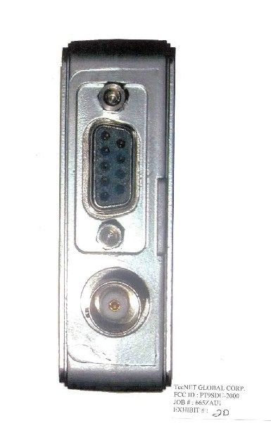
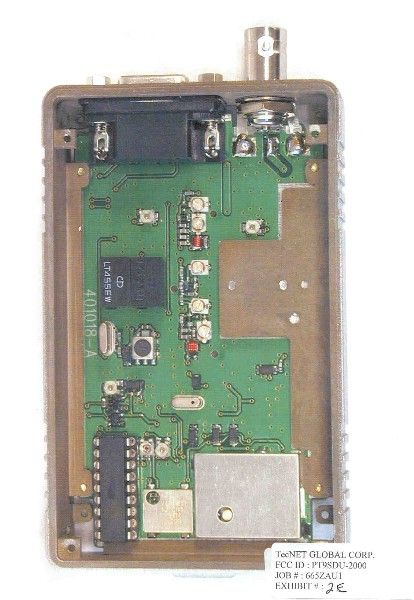
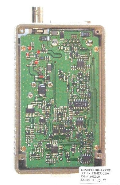
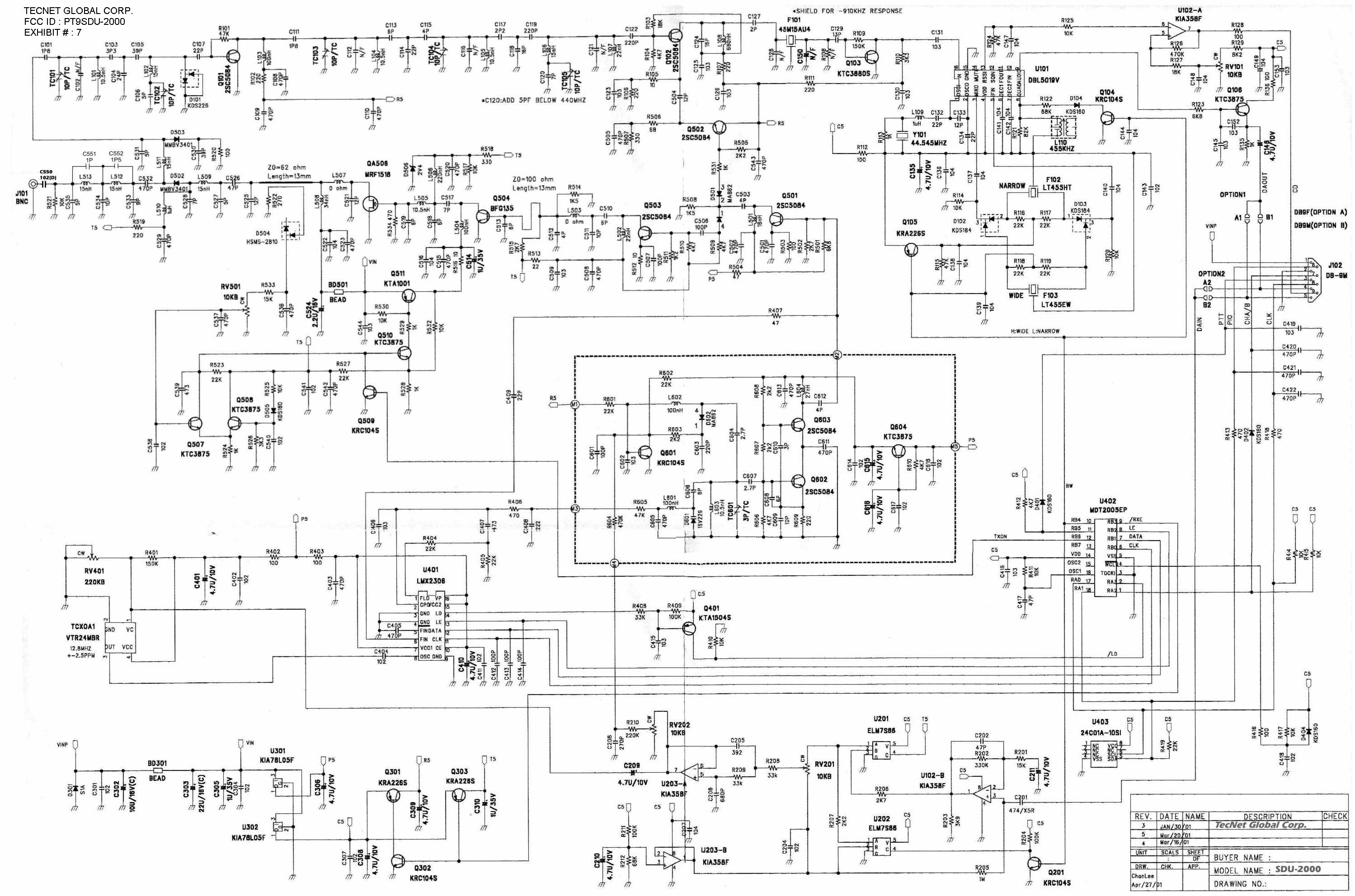
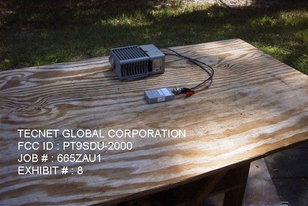
APPLICANT: TECNET GLOBAL CORPORATION FCC ID: PT9SDU-2000 REPORT #: T:\T\TECNET\665ZAU1\665ZAU1TestReport.doc TABLE OF CONTENTS TABLE OF CONTENTS LIST FOR PART 90 VHF DEVICE APPLICANT: TECNET GLOBAL CORPORATION FCC ID: PT9SDU-2000 TEST REPORT: PAGE 1......COVER SHEET - GENERAL INFORMATION & TECHNICAL DESCR. PAGE 2......MPE CALCULATION AND TECHNICAL DESCRIPTION PAGE 3......RF POWER OUTPUT, MOD CHARACTERISTICS PAGE 4......AUDIO FREQUENCY RESPONSE PLOT PAGE 5......MODULATION LIMITING – 300 Hz PAGE 6......MODULATION LIMITING – 12.5kHz – 1000 Hz PAGE 7......MODULATION LIMITING – 12.5kHz – 3000 Hz PAGE 8......OCCUPIED BANDWIDTH PAGE 9......OCCUPIED BANDWIDTH CONTINUED PAGE 10.....OCCUPIED BANDWIDTH PLOT – CW – 12.5 kHz – CHANNEL B PAGE 11.....OCCUPIED BANDWIDTH PLOT – CW – 25 kHz – CHANNEL A PAGE 12.....OCCUPIED BANDWIDTH PLOT – 9600 BAUD/825Hz – CH B PAGE 13.....OCCUPIED BANDWIDTH PLOT – 9600 BAUD/825Hz – 25kHz – CH A PAGE 14.....SPURIOUS EMISSIONS AT ANTENNA TERMINALS PAGE 15.....FIELD STRENGTH OF SPURIOUS EMISSIONS PAGE 16.....METHOD OF MEASURING RADIATED SPURIOUS EMISSIONS PAGE 17.....FREQUENCY STABILITY PAGE 18-19..TRANSIENT FREQUENCY STABILITY PAGE 20.....TRANSIENT FREQUENCY RESPONSE – 12.5kHz DEVIATION-1 PAGE 21.....TRANSIENT FREQUENCY RESPONSE – 12.5kHz DEVIATION-2 PAGE 22.....TRANSIENT FREQUENCY RESPONSE – 25kHz DEVIATION-1 PAGE 23.....TRANSIENT FREQUENCY RESPONSE – 25kHz DEVIATION-2 PAGE 24.....LIST OF TEST EQUIPMENT EXHIBITS CONTAINING: EXHIBIT 1A........FCC ID LABEL SAMPLE EXHIBIT 1B........SKETCH OF FCC ID LABEL LOCATION EXHIBIT 2A........EXTERNAL PHOTO – FRONT VIEW EXHIBIT 2B........EXTERNAL PHOTO – REAR VIEW EXHIBIT 2C........EXTERNAL PHOTO – SIDE VIEW EXHIBIT 2D........EXTERNAL PHOTO – TOP VIEW EXHIBIT 2E........INTERNAL PHOTO – COMPONENT VIEW EXHIBIT 2F........INTERNAL PHOTO – COPPER VIEW EXHIBIT 3.........USER’S MANUAL EXHIBIT 4.........THEORY OF OPERATION EXHIBIT 5.........TUNING PROCEDURES AND PROGRAMMING EXHIBIT 6.........BLOCK DIAGRAM EXHIBIT 7.........SCHEMATIC EXHIBIT 8.........TEST SET UP PHOTO APPLICANT: TECNET GLOBAL CORPORATION FCC ID: PT9SDU-2000 REPORT #: T:\T\TECNET\665ZAU1\665ZAU1TestReport.doc Page 1 of 24 GENERAL_INFORMATION_REQUIRED FOR_TYPE_ACCEPTANCE 2.1033 TECNET GLOBAL CORPORATION will sell the (c)(1)(2) FCC ID: PT9SDU-2000 UHF transceiver in quantity, for use under FCC RULES PART 22 & 90. 2.1033 (c) TECHNICAL DESCRIPTION 2.1033 (3) User Manual See Exhibit 3 MODELS SDU-2000 AND TNET-44 SHARE THE SAME USERS MANUAL 2.1033 (4) Type of Emission: 20K0F2D For 25 kHz 10K0F2D For 12.5 kHz For 25 kHz Bn = 2M + 2DK M = 19,200Bits per second D = 0.4 kHz (Peak Deviation) K = 1 Bn = 2(19,200/2) + 2(10.4k)(1) = 19.2k + 0.8k = 20.0K ALLOWED AUTHORIZED BANDWIDTH = 20.00 kHz. For 12.5 kHz Bn = 2M +2DK M = 9600Bits per second D = 0.825 kHz (Peak Deviation) K = 1 Bn = 2(9.6/2) K + 2(0.825k)(1) = 9.6k = 1.65k = 11.25 k ALLOWED AUTHORIZED BANDWIDTH = 11.25 kHz. 90.209(b)(5) 2.1033 (5) Frequency Range: 450-470 MHz (6) Power Range and Controls:There are NO user Power controls. (7) Maximum Output Power Rating: 4.5 Watts , into a 50 ohm resistive load. (8) DC Voltages and Current into Final Amplifier: POWER INPUT FINAL AMPLIFIER ONLY Vce = 13.6 Volts IC = 1.2A Pin = 16.3 Watts Efficiency = 27.6% APPLICANT: TECNET GLOBAL CORPORATION FCC ID: PT9SDU-2000 REPORT #: T:\T\TECNET\665ZAU1\665ZAU1TestReport.doc Page 2 of 24 2.1093 RF exposure is intended to be handled during licensing by the responsible FCC bureau(s).The transmitter is intended to operate with a 10% duty cycle. An example MPE calculation is based on continuous exposure. A Yagi antenna with a gain 6 dBd and a distance of 2 m was used. GdB6 gain of ant in dB G10 GdB 10 G 3.981 = gain of antenna P4500R1200 P is power in mW R1 is distance in cm MPG . S1 PG . 4 π R1 2 . M1.79110 4 = S10.036 = Power density in mW/cm^2 Calculated maximum exposure based on OET 65. f/300 for occupational limits. f/1500 for general public. f was taken as 470 MHz giving 1.57 mW/cm^2 for occupational and 0.31 mW/cm^2 for general population. 2.1033 (9) Tune-up procedure. MODELS SDU-2000 and TNET-44 Share the same tuning procedure. The tune-up procedure is given in EXHIBIT 5. 2.1033(10) Complete Circuit Diagrams: The circuit diagram is included as EXHIBIT 7. The block diagram is included as EXHIBIT 6. (11) A photograph or drawing of the equipment Identification label is shown in Exhibit 1. 2.1033(c)(12) Photographs of the equipment of sufficient clarity to reveal equipment construction and layout and label location are shown in Exhibits 1-2F. 2.1033(c)(13) For equipment employing digital modulation, a detail description of the modulation technique. This UUT uses FSK to modulate the transmitter. 2.1033(c)(14) data required for 2.1046 to 2.1057 SEE Below APPLICANT: TECNET GLOBAL CORPORATION FCC ID: PT9SDU-2000 REPORT #: T:\T\TECNET\665ZAU1\665ZAU1TestReport.doc Page 3 of 24 2.1046(a) RF_power_output . Is measured by connecting a 50 ohm, resistive wattmeter to the RF output connector. With a nominal battery voltage of 13.6VDC, and the transmitter properly adjusted. OUTPUT POWER = 4.5 Watts METHOD OF MEASURING RF POWER OUTPUT Transmitter 50 ohm under test Resistive Wattmeter Power Supply 2.1047(a) MODULATION CHARACTERISTICS NOT APPLICABLE, F2 type of emission. 2.1049 AUDIO LOW PASS FILTER This UUT does not have a low pass filter. 2.1049 AUDIO INPUT VS MODULATION The audio frequency input vs deviation was measured in accordance with TIA/EIA Specification 603 S2.2.6.2.1 with the following Exceptions ; starting with 1000 Hz., the input was increased well beyond the deviation changing. This measurement was repeated for the band limits and any frequency deemed appropriate. See Pages 4-7. RMS VOLT METER Transmitter Standard TEST under test Transmitter RECEIVER Probe APPLICANT: TECNET GLOBAL CORPORATION FCC ID: PT9SDU-2000 REPORT #: T:\T\TECNET\665ZAU1\665ZAU1TestReport.doc Page 4 of 24 TecNet Intrnational Inc. SDU-2000 0 10 20 30 40 50 60 70 80 90 100 10010001000…
Text truncated - open the document above for the full version.
Contact Information
Applicant
David Stubbs
Technical Contact
Timco Engineering, Inc.Mario R de Aranzeta
[email protected]888-472-2424
849 N.W. State Road 45 · Newberry, Florida · United States
Non-Technical Contact
Timco Engineering, Inc.Sharon A Hoffman
[email protected]888-472-2424
Test Firm
Timco Engineering, Inc.S Sanders
Technical Specifications
| # | Rule Parts | Frequency Range | Power Output | Emission | Tolerance |
|---|---|---|---|---|---|
| 2 | 22,9 | 450 MHz - 470 MHz | 4.5 W | 11K2F2D | 1.5 ppm |
Other Applications from TecNet Global Corporation

PT9SDU-7000
Dec 04, 2001UHF Telemetry Transceiver
Equipment Class
TNB - Licensed Non-Broadcast Station Transmitter