PTOITATRANSafety Location Device
Innovative Technology of America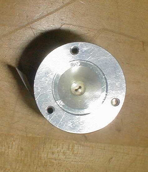
Click to zoom
Application Details
- Equipment Class
- TNB - Licensed Non-Broadcast Station Transmitter
- Date of Grant
- Sep 13, 2001
- Application Purpose
- Original Equipment
- Date of Application
- Sep 13, 2001
- Equipment Note
- Safety Location Device
- Frequency Range
- 24100.00000000 - 24100.00000000
- Country
- United States
Documents & Files
Document Text
Text extracted from the exhibit documents filed with the FCC. Open a document above to read the original.
Users Manual
Innovative Technology of America ST2000 Safety Transmitter Installation Procedure - Striping Vehicle 1. Supplied Material Drill Template 8-32 Button heads screws Interconnect (power) cable 2. Tools required Wire stripper Screwdriver with “Allen Wrench” head Drill and #18 bit (8-32 screws) plus 1.2” bit (antenna aperture) Tube of clear silicon gasket seal 3. Mounting the transmitters 3a. Place the drill template at the desired location. Drill the four holes with the #18 bit. Repeat this procedure at the other end of the vehicle. Drill out the center hole with the 1.2-inch bit. 3b. Coat the front metal surface only with clear silicon gasket seal. 3c. With one person inside with the transmitter and one outside align the transmitter and mount with the 8-32 screws. Wipe off any sealant the may be on the clear lens of the antenna. 4. Wiring 4a. Power Connectors. Connect the black wire to chassis ground. Connect the red wire to one of the red wires from switch box if manual turn-on/off of the transmitters is desired. Otherwise connect red wire to the desired 12-volt power source in the vehicle. Connect the green wire to one of the green wires from the switch box. 4b. Switch box. Green wires connected per above. Black wire to chassis ground. Red wire labeled “power” to 12-volt power in vehicle (manual turn-on/off) Two red wires (unmarked) per above for manual turn-on/off NOTE-Red wires are not connected if manual on/off is not desired. January 1, 2001 Innovative Technology of America ST2000 Safety Transmitter School Bus – Installation Procedure 1. Supplied Material Drill Template 8-32 Button heads screws Interconnect (power) cable 2. Tools required: Wire stripper Multimeter Screwdriver with “Allen Wrench” head Drill and #18 bit (8-32 screws) plus 1.2” bit (antenna aperture) Tube of clear silicon gasket seal 3. General Determine the power input terminal on the flashers that activate the top red lights. It may require contacting the school bus manufacturer for the flasher locations since it differs between manufacturers and models. Verify the terminal with the multimeter by measuring 12 volts when the lights are activated. Record this information. 4. Mounting the transmitters 4a. Place the drill template above and between the top red and yellow lights on the driver’s side. The drill template is butted against the edges of the red and yellow lights for positioning purposes. Drill the four holes with the #18 bit. Repeat this procedure at the other end of the bus. Drill out the center hole with the 1.2-inch bit. 4b. Coat the front metal surface with clear silicon gasket seal. 4c. With one person inside and one outside align the transmitter and mount with the 8-32 screws. Wipe off any sealant the may be on the clear lens of the antenna. 5. Wiring 5a. Plug the interconnect cables into the transmitter connectors. 5b. Connect the black wire to chassis ground and the red wire to the flasher input terminal. 6. Operation Extend the stop arm - the red flasher and SWS transmitters are activated with the transmitters sending the message “School Bus Loading/Unloading” to approaching vehicles.
Cover Letter(s)
Phone 217 351-8805 2702 No. Mattis Avenue Fax 217 351-8803 Champaign, IL 61822 Request for Confidentiality March, 24, 2001 American Telecommunications Certification Body, Inc. 6731 Whittier Avenue Suite C110 McLean, VA 22101 RE: Certification Application for ST2000 Microwave Transmitters FCC ID: PTOITATRAN Please be advised that the following information is to be held confidential and behalf of Innovative Technology of America: • Schematic • Theory of Operation The application contains technical information which Innovative Technology of America deems to be trade secrets and proprietary. If made public, the information might be used to the disadvantage of the applicant in the market place. Thank you for your attention to this matter.
Cover Letter(s)
Phone 217 351-8805 2702 No. Mattis Avenue Fax 217 351-8803 Champaign, IL 61822 Letter Of Agency March 24, 2001 American Telecommunications Certification Body, Inc. 6731 Whittier Avenue Suite C110 McLean, VA 22101 To Whom It May Concern: Please be advised that Innovative Technology of America authorizes Washington Laboratories, Ltd. to act on our behalf, until otherwise notified, for applications submitted to American Telecommunications Certification Body, Inc. (ATCB). We certify that we are not subject to denial of federal benefits, that includes FCC benefits, pursuant to Section 5301 of the Anti-Drug Abuse ACT of 1988, U.S.C. 862. Further, no party, as defined in 47 CFR 1.2002(b), to the application is subject to denial of federal benefits, that includes FCC benefits. Thank you for your attention to this matter.
External Photos
Overall View Connector End Horn End
ID Label/Location Info
PTOITATRAN
Internal Photos
Internals Removed From Housing PCB Top PCB Bottom
Operational Description
ST2000 SWS Safety Transmitter Theory of Operation Critical components: U1 12 bit DAC U2 24.1000 GHz Gunn Oscillator with bias input to adjust frequency U3 4,096 bit temperature sensor U5 Microcontroller with Flash memory The ST2001 is tested and configured by a computer-based test station which installs the determined Gunn Oscillator bias vs. frequency data, Gunn Oscillator temperature vs. frequency data and the specific text data (SWS specified) for the messages required by the customer into the memory of U2. Data transmission Data bit: U5 sends data to U1 and sets the bias voltage of the Gunn Oscillator. A data bit consists of 20 individual bias levels creating a FM data bit. The resultant FM data bit is a change in the transmitted frequency of 5 MHz over 500 microseconds (2 KHz bit rate). A one bit equals –2.5 MHz to + 2.5Mhz change while a zero bit equals a +2.5 MHz to – 2.5Mhz change. Message: 1. CW Marker - 24.1 GHz for 522 milliseconds 2. Header field – 12 bits (all ones) 3. Text field 1 – 10 bits 4. Text field 2 – 10 bits 5. Text data repeated a total of 9 times Operation: U5 receives the temperature of the Gunn Oscillator from U3 upon turn-on and sets the transmitted frequency to 24.100 GHz plus or minus 20 MHz by setting the bias voltage (U1) in accordance with the bias vs. frequency data and temperature vs. frequency data stored in memory. The specific message is then transmitted. The transmitter is continuously calibrated during operation by this closed-loop system resulting in a Gunn Oscillator that has an inherent 1 to 1.4 MHz change per degree centigrade remaining within a total of 20 MHz across the minus 30 to plus 50 degree centigrade ST2000 operating temperature range. Message selection: The selection of the transmitted is accomplished by changing the grounds on pins three through six of J3 resulting in the ability to select up to 16 pre-loaded SWS messages.
Test Report
Document 6415-01, Rev. 0 FCC Certification Test Report Washington Laboratories, Ltd August 2001 FCC Certification Test Report for Innovative Technology of America FCC ID: PTOITATRAN August 29, 2001 Prepared for: Innovative Technology of America 2702 North Mattis Avenue Champaign, IL 61822 Prepared By: Washington Laboratories, Ltd. 7560 Lindbergh Drive Gaithersburg, Maryland 20879 FCC Certification Test Report Document 6415-01, Rev. 0 FCC Certification Test Report Washington Laboratories, Ltd August 2001 FCC Certification Test Program FCC Certification Test Report for the Innovative Technology of America ST2000 SWS Safety Transmitter FCC ID: PTOITATRAN August 29, 2001 WLL JOB# 6415 Prepared by: Brian J. Dettling Documentation Specialist Reviewed by: Michael Violette President Document 6415-01, Rev. 0 FCC ID: PTOITATRAN FCC Certification Test Report Washington Laboratories, Ltd August 2001 ii Abstract This report has been prepared on behalf of Innovative Technology of America to support the attached Application for Equipment Authorization. The test report and application are submitted for a Safety Warning Transmitter under Part 90.103 of the FCC Rules and Regulations. This Federal Communication Commission (FCC) Certification Test Report documents the test configuration and test results for a Innovative Technology of America ST2000 SWS Safety Transmitter. Testing was performed on an Open Area Test Site (OATS) of Washington Laboratories, Ltd, 7560 Lindbergh Drive, Gaithersburg, MD 20879. Site description and site attenuation data have been placed on file with the FCC's Sampling and Measurements Branch at the FCC laboratory in Columbia, MD. Washington Laboratories, Ltd. has been accepted by the FCC and approved by NIST NVLAP (NVLAP Lab Code: 200066-0) as an independent FCC test laboratory. The Innovative Technology of America ST2000 SWS Safety Transmitter complies with the limits for a Safety Warning System device under Part 90.103 of the FCC Rules and Regulations. Document 6415-01, Rev. 0 FCC ID: PTOITATRAN FCC Certification Test Report Washington Laboratories, Ltd August 2001 iii Table of Contents Abstract......................................................................................................ii 1 Introduction...................................................................................................................1 1.1 Compliance Statement............................................................................................1 1.2 Test Scope............................................................................................................1 1.3 Contract Information..............................................................................................1 1.4 Test Dates.............................................................................................................1 1.5 Test and Support Personnel....................................................................................1 1.6 Abbreviations.........................................................................................................1 2 Equipment Under Test....................................................................................................2 2.1 EUT Identification & Description............................................................................2 2.2 Test Configuration..................................................................................................3 2.3 Testing Algorithm...................................................................................................3 2.4 Test Location.........................................................................................................3 2.5 Measurements........................................................................................................3 2.5.1 References.....................................................................................................3 2.6 Measurement Uncertainty.......................................................................................3 3 Test Equipment..............................................................................................................4 4 Test Results...................................................................................................................4 4.1 Output Power (§2.1046)........................................................................................4 4.2 Spurious Emissions at antenna terminals (§2.1051)..................................................5 4.3 Frequency Stability (§2.1055)................................................................................5 4.3.1 Frequency as a Function of Applied Voltage...................................................5 4.3.2 Frequency as a function of Temperature..........................................................5 4.4 Spurious Emissions (§2.1053)................................................................................6 4.5 Occupied Bandwidth: (FCC Part §2.1049)............................................................6 4.6 Necessary Bandwidth (§2.202)..............................................................................8 5 Radiofrequency radiation evaluation exposure (§2.1091).................................................8 Document 6415-01, Rev. 0 FCC ID: PTOITATRAN FCC Certification Test Report Washington Laboratories, Ltd August 2001 iv List of Tables Table 1. Device Summary....................................................................................................2 Table 2: Test Equipment List...............................................................................................4 Table 3. Frequency Deviation as a Function of Applied Voltage............................................5 Table 4. Frequency Deviation as a Function of Temperature..................................................6 Table 5. Field Strength Measurements..............................................................…
Text truncated - open the document above for the full version.
Contact Information
Applicant
Jay Schreiber(President)
Technical Contact
Washington LaboratoriesGreg Snyder
[email protected]301-417-0220
7560 Lindbergh Drive · Gaithersburg, Maryland · United States
Non-Technical Contact
Washington LabsBrian Dettling
[email protected]301-417-0220
Test Firm
Washington Laboratories, Ltd.Michael Violette
Technical Specifications
| # | Rule Parts | Frequency Range | Power Output | Emission | Tolerance |
|---|---|---|---|---|---|
| 1 | 90 | 24.10 GHz - 24.10 GHz | 10.00 mW | 6M00F1D | 2000.0000000000 Hz |