PTP-TY1401In-Car
Salutica Allied Solutions Sdn. Bhd.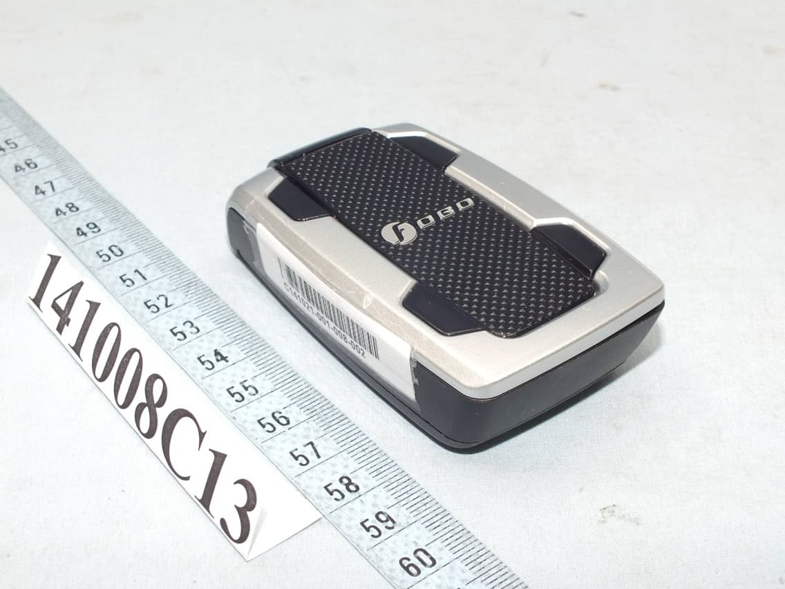
Click to zoom
Application Details
- Equipment Class
- DTS - Digital Transmission System
- Date of Grant
- Nov 11, 2014
- Application Purpose
- Original Equipment
- Date of Application
- Nov 11, 2014
- Equipment Note
- In-Car
- Frequency Range
- 2402.00000000 - 2480.00000000
- Country
- Malaysia
Documents & Files
Document Text
Text extracted from the exhibit documents filed with the FCC. Open a document above to read the original.
Users Manual
1 | P a g e FOBO Tire User Manual Version 1.1 (for iOS7.1 and Android 4.30 & above) 2 | P a g e Contents 1 Introduction 2 About FOBO Tire 3 Importance of tire care 4 Description of FOBO Tire 4.1 In-Car unit 4.2 Tire Sensor unit 4.3 Sensor lock nuts & wrench 5 Start to use FOBO Tire 5.1 Installing FOBO Tire app 5.2 Installing FOBO Tire In-car unit and sensors 5.3 Setting up multiple users 5.4 Tire rotation 5.5 Disable sensor and Replace new sensor 5.6 Transfer FOBO Tire to another user 6 FOBO Tire Alert Messages 7 In-Car unit audio & LED alerts 8 Replacing Battery 9 Trouble Shooting Guide 10 FOBO Tire Specifications 11 Warning 12 Regulatory Information 13 Intellectual Properties 14 Limited Warranty and Disclaimer 3 | P a g e 1 Introduction FOBO Tire is the world’s most advanced Tire Pressure Monitoring System (TPMS) using Bluetooth Smart (Bluetooth 4.0) technology to monitor your car tire pressure and temperature. Bluetooth Smart is a very low power wireless technology that could operate on a single coin cell battery for up to two years (NOTE: Battery life may vary according to usage and climatic temperature. Operating under extreme cold may drastically reduce battery life.) Please ensure that your smart phone has Bluetooth Smart Ready (Bluetooth 4.0) capability in order to use FOBO Tire. Currently FOBO Tire works best with iOS7.1 and Android 4.30 and above. Before starting to use FOBO Tire, please download the free FOBO Tire app to your smart phone from Google PlayStore or Apple AppStore. FOBO Tire is a product designed and produced by Salutica Allied Solutions Sdn. Bhd. (“Salutica”), a Malaysian company with its address at No. 3, Jalan Zarib 6, Kawasan Perindustrian Zarib, 31500 Lahat, Ipoh, Perak, Malaysia. 2 About FOBO Tire FOBO Tire monitors your car tires non-stop around the clock. Most drivers have encountered situations where they need to rush for an urgent appointment only to be halted by a flat tire. Conventional Tire Pressure Monitoring Systems (TPMS) could not pre-alert you because they stop operating as soon as the car ignition is switched-off. With FOBO Tire, you will get an alert as soon as the tire pressure drops below a certain pre-set level, even when the car ignition is switched off. You will be alerted if you are within Bluetooth range (~30m). This pre-alert gives you time to get the flat tire fixed before you need to use the car for next appointment. FOBO Tire can monitor up to 20 cars on each smart phone. This gives the user full information of the tires for all the cars without switching on. You will know which car tire is under-inflated without having to start the car engines one by one. NOTE: Under certain conditions the signals from FOBO Tire sensors may be blocked by surrounding objects or structures. If this occurs, please move around the vehicle in order to capture signals from all the tire sensors. 4 | P a g e For those who are sharing car with family members or friends, you can allow others to use your FOBO Tire with permission. And it is simple, just key in the e-mail address that the other user will be using to login to FOBO Tire app. FOBO Tire consists of four sensors and one in-car unit. Replace your tire valve caps with the sensors and place the in-car unit inside the car. The sensors will measure tire pressure of each tire and transmit via Bluetooth to the in-car unit. In case of any problem, the in- car unit will produce alert sound to notify user of any problem. In-car unit also comes with LEDs to show position of the problematic tire. FOBO Tire system requires a smart phone and app for installation. Besides being able to view more information of your car tires, the smart phone app will also produce alert sound when your tire has a problem. DISCLAIMER: FOBO TIRE IS NOT AN ANTI-ACCIDENT DEVICE AND IT IS NOT A SUBSTITUTE FOR SAFE TIRE MAINTENANCE PRACTICES. PLEASE CONTINUE TO TAKE PRECAUTIONARY MEASURES WHILE DRIVING AND TAKE FULL RESPONSIBILITY OF YOUR VEHICLE’S TIRE CONDITION TO ENSURE SAFETY WHILE DRIVING. YOU SHOULD CONTINUE TO PRACTICE PROPER TIRE CARE AND SCHEDULED TIRE MAINTENANCE. 5 | P a g e 3 Importance of tire care It is extremely important to ensure car tires are properly inflated for safety while driving. However, most drivers tend to neglect proper tire care and maintenance. Car tires are the only contact holding the car to the road. The air pressure inside the tires is supporting the weight of the car and passenger loads. Improperly inflated car tires may cause serious accidents on the road. When the car tires are underinflated, the full weight of the car may compress and distort the tire side walls. Continued use of underinflated tires may lead to heat build-up and cause de-lamination of the tire materials thus increasing chances of tire blow-out. Underinflated tires will also wear faster around the tire shoulders causing uneven tire wear. Gas mileage will reduce due to more drag when driving with underinflated tires. For some drivers, they tend to overinflate their car tires to get better mileage. However an overinflated car tire tends to bulge at the center radial causing uneven wear. Water dispersion may also be affected when tires are overinflated increasing chances of hydroplaning. That’s when the car may spin out of control when driving on wet road. What is the optimum tire pressure? There are a lot of information about this subject in internet forums and web articles. A quick guide for better understanding of tire pressure below: 1) Car manufacturers recommend the optimum tire pressure for their car models. The information is usually available on a sticker at the door jam (side of the driver’s door) or in the owner’s manual. For some car models, the information sticker may be on the trunk lid or on the fuel door. Car manufacturers usually recommend different tire pressure for front and rear tires. This pressure is usually recommended for comfort driving and optimum performance of the car. It is not advisable to go below this reco…
Text truncated - open the document above for the full version.
External Photos
Page 1 CONSTRUCTION PHOTOS OF EUT
ID Label/Location Info
Label location
Internal Photos
Page 2 Page 3 Page 4
Operational Description
FCC ID: PTP-TY1401 Report No.: RF141008C13 OPERATIONAL DESCRIPTION The transmitter of the EUT (In-Car) is powered from 3Vdc from battery. The antenna is Printed antenna without antenna connector. For more detailed instruction, please take a look at the user’s manual.
RF Exposure Info
Report No.: SA141008C13 1 of 5 Report Format Version 5.2.0 RF EXPOSURE REPORT REPORT NO.: SA141008C13 MODEL NO.: TY1401 FCC ID: PTP-TY1401 RECEIVED: Oct. 08, 2014 TESTED: Nov. 03 ~ Nov. 04, 2014 ISSUED: Nov. 06, 2014 APPLICANT: Salutica Allied Solutions Sdn. Bhd ADDRESS: 3 Jalan Zarib 6, Kawasan Perindustrian Zarib, 31500 Lahat Ipoh, Perak, Malaysia ISSUED BY: Bureau Veritas Consumer Products Services (H.K.) Ltd., Taoyuan Branch LAB ADDRESS: No. 47-2, 14th Ling, Chia Pau Vil., Lin Kou Dist., New Taipei City, Taiwan, R.O.C. TEST LOCATION: No. 19, Hwa Ya 2nd Rd, Wen Hwa Tsuen, Kwei Shan Hsiang, Taoyuan Hsien 333, Taiwan, R.O.C. This report is for your exclusive use. Any copying or replication of this report to or for any other person or entity, or use of our name or trademark, is permitted only with our prior written permission. This report sets forth our findings solely with respect to the test samples identified herein. The results set forth in this report are not indicative or representative of the quality or characteristics of the lot from which a test sample was taken or any similar or identical product unless specifically and expressly noted. Our report includes all of the tests requested by you and the results thereof based upon the information that you provided to us. You have 60 days from date of issuance of this report to notify us of any material error or omission caused by our negligence, provided, however, that such notice shall be in writing and shall specifically address the issue you wish to raise. A failure to raise such issue within the prescribed time shall constitute your unqualified acceptance of the completeness of this report, the tests conducted and the correctness of the report contents. Unless specific mention, the uncertainty of measurement has been explicitly taken into account to declare the compliance or non-com pliance to the specification. This report should not be used by the client to claim product certification, approval, or endorsement by any government agencies. Report No.: SA141008C13 2 of 5 Report Format Version 5.2.0 TABLE OF CONTENTS RELEASE CONTROL RECORD ................................................................................................ 3 1. CERTIFICATION ............................................................................................................ 4 2. RF EXPOSURE .............................................................................................................. 5 2.1 LIMITS FOR MAXIMUM PERMISSIBLE EXPOSURE (MPE) ........................................ 5 2.2 MPE CALCULATION FORMULA ................................................................................... 5 2.3 CLASSIFICATION .......................................................................................................... 5 2.4 CALCULATION RESULT OF MAXIMUM CONDUCTED POWER ................................. 5 Report No.: SA141008C13 3 of 5 Report Format Version 5.2.0 RELEASE CONTROL RECORD ISSUE NO. REASON FOR CHANGE DATE ISSUED SA141008C13 Original release. Nov. 06, 2014 Report No.: SA141008C13 4 of 5 Report Format Version 5.2.0 1. CERTIFICATION PRODUCT:In-Car MODEL NO.:TY1401 BRAND: FOBO APPLICANT:Salutica Allied Solutions Sdn. Bhd TESTED:Nov. 03 ~ Nov. 04, 2014 TEST SAMPLE:ENGINEERING SAMPLE STANDARDS: FCC Part 2 (Section 2.1091) KDB 447498 D03 IEEE C95.1 The above equipment (model: TY1401) has been tested by Bureau Veritas Consumer Products Services (H.K.) Ltd., Taoyuan Branch, and found compliance with the requirement of the above standards. The test record, data evaluation & Equipment Under Test (EUT) configurations represented herein are true and accurate accounts of the measurements of the sample’s EMC characteristics under the conditions specified in this report. PREPARED BY :, DATE :Nov. 06, 2014 Celine Chou / Specialist APPROVED BY:, DATE :Nov. 06, 2014 Ken Liu / Senior Manager Report No.: SA141008C13 5 of 5 Report Format Version 5.2.0 2. RF EXPOSURE 2.1 LIMITS FOR MAXIMUM PERMISSIBLE EXPOSURE (MPE) FREQUENCY RANGE (MHz) ELECTRIC FIELD STRENGTH (V/m) MAGNETIC FIELD STRENGTH (A/m) POWER DENSITY (mW/cm 2 ) AVERAGE TIME (minutes) LIMITS FOR GENERAL POPULATION / UNCONTROLLED EXPOSURE 300-1500 ... ... F/1500 30 1500-100,000 ... ... 1.0 30 F = Frequency in MHz 2.2 MPE CALCULATION FORMULA Pd = (Pout*G) / (4*pi*r 2 ) where Pd = power density in mW/cm 2 Pout = output power to antenna in mW G = gain of antenna in linear scale Pi = 3.1416 R = distance between observation point and center of the radiator in cm 2.3 CLASSIFICATION The antenna of this product, under normal use condition, is at least 20cm away from the body of the user. So, this device is classified as Mobile Device. 2.4 CALCULATION RESULT OF MAXIMUM CONDUCTED POWER FREQUENCY BAND (MHz) MAX POWER (dBm) ANTENNA GAIN (dBi) DISTANCE (cm) POWER DENSITY (mW/cm 2 ) LIMIT (mW/cm 2 ) 2402-2480 4.18 -4 20 0.0002 1 ---END---
Test Report
Report No.: RF141008C13 1 of 29 Report Format Version 5.1.0 FCC TEST REPORT REPORT NO.: RF141008C13 MODEL NO.: TY1401 FCC ID: PTP-TY1401 RECEIVED: Oct. 08, 2014 TESTED: Nov. 03 ~ Nov. 04, 2014 ISSUED: Nov. 06, 2014 APPLICANT: Salutica Allied Solutions Sdn. Bhd ADDRESS: 3 Jalan Zarib 6, Kawasan Perindustrian Zarib, 31500 Lahat Ipoh, Perak, Malaysia ISSUED BY: Bureau Veritas Consumer Products Services (H.K.) Ltd., Taoyuan Branch LAB ADDRESS: No. 47-2, 14th Ling, Chia Pau Vil., Lin Kou Dist., New Taipei City, Taiwan, R.O.C. TEST LOCATION: No. 19, Hwa Ya 2nd Rd, Wen Hwa Tsuen, Kwei Shan Hsiang, Taoyuan Hsien 333, Taiwan, R.O.C. This report is for your exclusive use. Any copying or replication of this report to or for any other person or entity, or use of our name or trademark, is permitted only with our prior written permission. This report sets forth our findings solely with respect to the test samples identified herein. The results set forth in this report are not indicative or representative of the quality or characteristics of the lot from which a test sample was taken or any similar or identical product unless specifically and expressly noted. Our report includes all of the tests requested by you and the results thereof based upon the information that you provided to us. You have 60 days from date of issuance of this report to notify us of any material error or omission caused by our negligence, provided, however, that such notice shall be in writing and shall specifically address the issue you wish to raise. A failure to raise such issue within the prescribed time shall constitute your unqualified acceptance of the completeness of this report, the tests conducted and the correctness of the report contents. Unless specific mention, the uncertainty of measurement has been explicitly taken into account to declare the com pliance or non-compliance to the specification This report should not be used by the client to claim product certification, approval, or endorsement by TAF or any government agencies. Report No.: RF141008C13 2 of 29 Report Format Version 5.1.0 Table of Contents RELEASE CONTROL RECORD .............................................................................................. 4 1. CERTIFICATION ........................................................................................................... 5 2. SUMMARY OF TEST RESULTS .................................................................................. 6 2.1 MEASUREMENT UNCERTAINTY ................................................................................ 6 3. GENERAL INFORMATION ........................................................................................... 7 3.1 GENERAL DESCRIPTION OF EUT ............................................................................. 7 3.2 DESCRIPTION OF TEST MODES ............................................................................... 8 3.2.1 TEST MODE APPLICABILITY AND TESTED CHANNEL DETAIL ............................... 9 3.3 DESCRIPTION OF SUPPORT UNITS ....................................................................... 10 3.3.1 CONFIGURATION OF SYSTEM UNDER TEST ........................................................ 10 3.4 GENERAL DESCRIPTION OF APPLIED STANDARDS ............................................ 10 4. TEST TYPES AND RESULTS .................................................................................... 11 4.1 RADIATED EMISSION AND BANDEDGE MEASUREMENT ..................................... 11 4.1.1 LIMITS OF RADIATED EMISSION AND BANDEDGE MEASUREMENT .................. 11 4.1.2 TEST INSTRUMENTS ................................................................................................ 12 4.1.3 TEST PROCEDURES ................................................................................................ 13 4.1.4 DEVIATION FROM TEST STANDARD....................................................................... 13 4.1.5 TEST SETUP .............................................................................................................. 14 4.1.6 EUT OPERATING CONDITIONS ............................................................................... 14 4.1.7 TEST RESULTS ......................................................................................................... 15 4.2 6dB BANDWIDTH MEASUREMENT .......................................................................... 19 4.2.1 LIMITS OF 6dB BANDWIDTH MEASUREMENT ....................................................... 19 4.2.2 TEST SETUP .............................................................................................................. 19 4.2.3 TEST INSTRUMENTS ................................................................................................ 19 4.2.4 TEST PROCEDURE ................................................................................................... 19 4.2.5 DEVIATION FROM TEST STANDARD....................................................................... 19 4.2.6 EUT OPERATING CONDITIONS ............................................................................... 19 4.2.7 TEST RESULTS ......................................................................................................... 20 4.3 CONDUCTED OUTPUT POWER ............................................................................... 21 4.3.1 LIMITS OF CONDUCTED OUTPUT POWER MEASUREMENT ............................... 21 4.3.2 TEST SETUP .............................................................................................................. 21 4.3.3 TEST INSTRUMENTS ................................................................................................ 21 4.3.4 TEST PROCEDURES ................................................................................................ 21 4.3.5 DEVIATION FROM TEST STANDARD....................................................................... 21 4.3.6 EUT OPERATING CONDITIONS ........................…
Text truncated - open the document above for the full version.
Test Setup Photos
1 PHOTOGRAPHS OF THE TEST CONFIGURATION RADIATED EMISSION TEST
Contact Information
Applicant
Mohd Shahir(Senior Engineer)
Test Firm
Bureau Veritas CPS (H.K.) Ltd., Taoyuan BranchRichard Chen
Technical Specifications
| # | Rule Parts | Frequency Range | Power Output |
|---|---|---|---|
| 1 | 15C | 2.40 GHz - 2.48 GHz | 3.00 mW |
Other Applications from Salutica Allied Solutions Sdn. Bhd.
PTP-TN2601
Jul 14, 2026FOBO Next
Equipment Class
DTS - Digital Transmission System
PTP-TA1201
Jan 02, 2013FOBO Wireless Tag
Equipment Class
DTS - Digital Transmission System