PTTRFMX-1Interface Module and Freepad
Gecko Electronics Inc.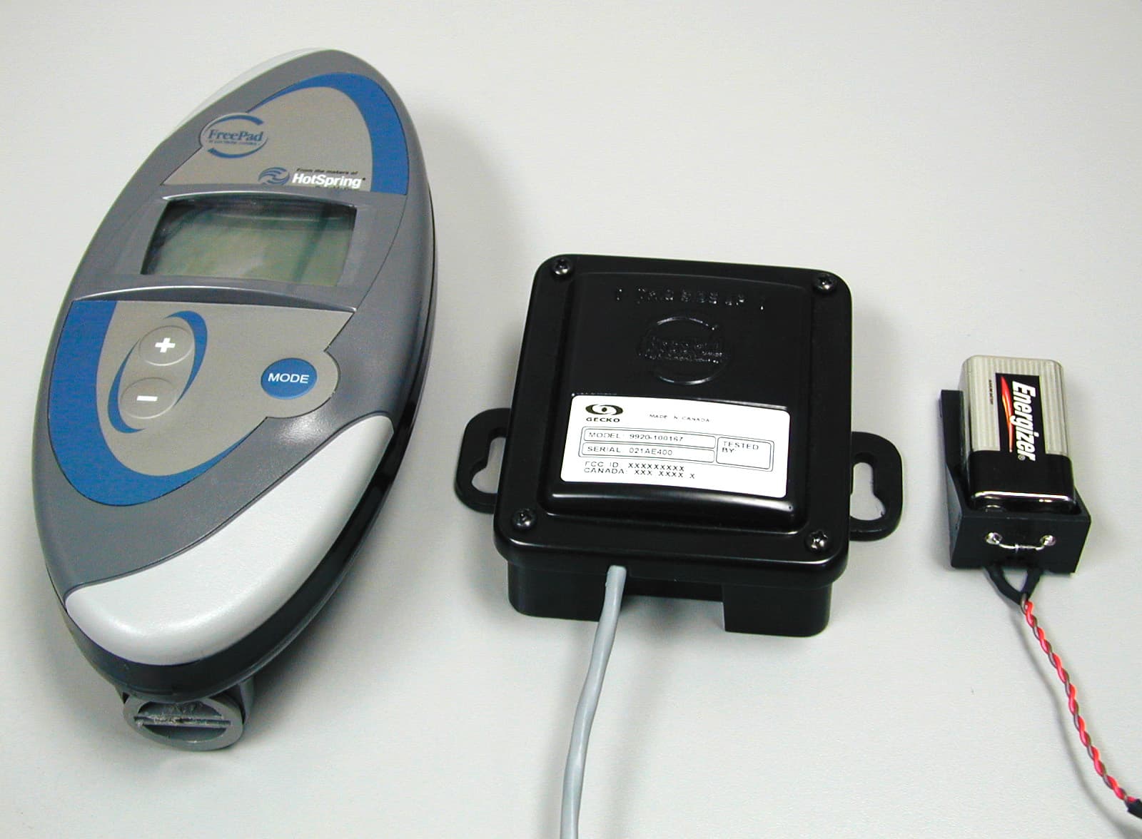
Click to zoom
Application Details
- Equipment Class
- DXT - Part 15 Low Power Transceiver, Rx Verified
- Date of Grant
- Nov 14, 2001
- Application Purpose
- Original Equipment
- Date of Application
- Aug 14, 2001
- Equipment Note
- Interface Module and Freepad
- Frequency Range
- 916.00000000 - 916.00000000
- Company
- Gecko Electronics Inc.
- Country
- Canada
Documents & Files
Document Text
Text extracted from the exhibit documents filed with the FCC. Open a document above to read the original.
Users Manual
Watkins Manufacturing Corp. FreePad Control System Welcome Tiger River models Press and hold the Tiger Key button on the spa’s Main controlpanel for two (2) seconds toinitiate desynchronization.Press any FreePad button towake the FreePad. When thedisplay illuminates, press theMinus button on the FreePad to complete the process. Battery SafetyPrecautions! Keep batteries out of reach of children ! Don’t mix old and new batteries, orbatteries of different types (alkalineand carbon). ! If a battery leaks, remove allbatteries and dispose of them inaccordance with your local laws.Clean the battery compartmentthoroughly before inserting newbatteries. Clean by followingbattery manufacturer’srecommendations for cleanup. Donot come in contact with fluid fromthe battery. If you do, flush skinwith water immediately. ! Always remove old, wornout, andweak batteries promptly. Dispose ofthe batteries in accordance with yourlocal laws. ! Remove batteries if your systemcontroller is to be stored for longerthan a month w ithout being used. Special BatteryPrecautionsThe precautions below are to prevent thesudden release of electrolytes, whichthese prohibited actions can cause:! Do not open, puncture, or mutilatethe batteries. ! Do not heat batteries in an attempt torecharge them. ! Do not use a fire to dispose ofbatteries. Released battery electrolyte is corrosive,can cause damage to the eyes and skin,and may be toxic if swallowed.Regulatory InformationThis product was tested and complieswith the limits for an intentional emitterunder Part 15 of the FederalCommunications Commission (FCC)rules, and operation is subject to theseconditions: (1) It may not cause harmfulinterference and (2) must accept anyinterference received, includinginterference that may cause undesiredoperation.FreePad Model # RFMT-1Interface Module # RFMR-1 ContentsWelcome.................................................................... 1 Exciting Features.......................................................... 1 Screen Display............................................................. 1 Product Content......................................................... 1 Interface Module........................................................... 1 Interface Module Installation............................................Starting FreePad for First Time......................................... 22 Battery Installation........................................................FreePad/IQ2020 Synchronization.......................................Using the FreePad.........................................................Screen Definitions.........................................................FreePad Overview.........................................................Control Screens............................................................Troubleshooting...........................................................Battery Safety Precautions...............................................Special Battery Precaution...............................................RegulatoryInformation......................................................Technical Support.........................................................Warranty Information..................................................... 223334455556 This Owner’s Manual w ill ac quaint you with the installation and operation of the FreePadControl System. We suggest that you take some time to carefully review allof this Owner’s Manual. Please keep this manual available for reference.If you have any questions about any aspect of your FreePad’s set-up, operation, ormaintenance, contact your authorized Spa Dealership. They are trainedprofessionals who are fam iliar with the pr oduct. Their expertise w ill facilitate the enjoyment of your new FreePad.IMPORTANT: Watkins Manufacturing Corporation reserves the right to change specifications or design wit hout no tification and without incurring any obligation. Watkins Manufacturing Corp. FreePad Control System Technical SupportIf you are living in the USA, please call1-800-999-4688 (extention 432) Mondaythrough Friday, 8a.m. to 5p.m. Pacific Standard Time (PST) or [email protected] . Watkins Manufacturing Corporation1280 Park Center DriveVista, CA 92083Interface ModuleInstallationTo install the Interface Module, thefollowing is required:1. Disconnect the Main Power goinginto the spa. 2. Remove the equipment compartmentdoor of the spa. 3. Attach the Module to the spa usingthe two (2) existing screws on theInterface Module label attached tothe spa wall inside the equipmentcompartment). 4. Open the IQ2020 Control Box byremoving the two (2) front screwsand front cover. 5. Attached cable to the low voltageconnector as illustrated below. 6. Close IQ2020 Control Box byattaching cover and fastening usingthe two (2) screws. 7. Replace equipment compartmentdoor onto spa. 8. Connect Main Power to spa. Starting The FreePadfor the First TimeStarting the FreePad for the first timerequires one (1) step:1. Installing the batteries into theFreePad. Battery InstallationThe FreePad uses three AA alkalinebatteries supplied with this packet.Insert a quarter into the slot inside theplug at the bottom of the FreePad, rotatecounter clockwise to open. Install thebatteries with the positive (+) endtowards the top of the FreePad and thenegative (-) end towards the bottom.Once the batteries are installed, replacethe plug and tighten with a quarter.NOTE: It is recommended that all three batteries be replaced at the same time.FreePad/IQ2020Synchronization The Freepad comes pre-synchronized tothe Interface Module. Since the IQ2020will communicate with up to eight (8)FreePad controllers, any additionalcontrollers will need to be manuallysynchronized. The following is requiredto synchronize a FreePad controller w iththe Interface Module: HotSpring models 1. Press and hold both the Light Plus and the Light Minus buttons on the spa’s Main control panelsimultaneously for two (2) secondsto initiate sync…
Text truncated - open the document above for the full version.
Block Diagram
FreePad and Interface Module Description1/5 FreePad and Interface Module – Application General Circuit Description The FreePad RF Remote Control and the RF Interface Module are part of a complete Spa System. Spa Electronic Controller: This Spa System uses a Spa Electronic Controller which is a black box located under the skirt of a spa. The Spa Electronic Controller provides power to all the pumps, heaters, blower, temperature probe and the like of the spa system. To do so, the Spa Electronic Controller has microcontroller based control circuits for timer, temperature regulation, pump and other control functions. Spa System Freepad RF Remote Control RF Interface Module Spa Electronic Controller Supply dc I2C Link Pump #1 Pump #2 Other Accessories Spa system using the FreePad RF Remote Control and the RF Interface Module FreePad and Interface Module Description2/5 FreePad RF Remote Control: The FreePad RF Remote Control is the user interface that sends commands to the Spa Electronic Controller and that receives status information from the Spa Electronic Controller. It does so through RF Communication. The FreePad RF Remote Control electronic circuit is located inside a plastic housing. There is two separated Printed Circuit Boards (PCB) in this housing. The first PCB is the RF PCB. This is where all RF communication functions are located. The RF PCB is mounted over a second PCB, which is the Control Board. This control board comprises batteries, keypad, LCD and a μController. It is this Control Board that controls the power supply, the keypad, the LCD and that manages the input/output data exchange between the μController and RF PCB. These exchanges of input/output data are done through a 34 Kbaud, 8bits serial link. FreePad RF Remote Control Control Board Power Supply Batteries μController LCDKeypad 34 KBaud 8 Bits Serial RF PCB Transceiver Antenna FreePad and Interface Module Description3/5 The RF Interface Module: The RF Interface Module is the electronic circuitry that translates the RF communication data stream (from/to the FreePad RF Remote Control) to a low frequency digital data stream from/to the Spa Electronic Controller. The RF Interface Module is located inside a plastic box. This plastic box is connected to the Spa Electronic Controller through a 4 wire cable that provide a +5Vdc supply and the I 2 C serial communication link. There is two separated Printed Circuit Boards in this RF Interface Module housing. The first PCB is the RF PCB. This is where all RF communication functions are located. This is the exact same RF PCB as with the FreePad RF Remote Control. It has the same PCB, same layout, same components and same onboard antenna. As with the FreePad, the RF PCB is mounted over a second PCB, which is the Interface Module Control Board. This Interface Module Control Board has only one function. It communicates with the RF PCB through the 34 Kbaud, 8bits serial link and translates this data stream to the I 2 C serial communication link that connects to the Spa Electronic Controller. RF Interface Module 34 KBaud 8 Bits Serial RF PCB Transceiver Antenna Interface Module Control Board μController I2C Link Spa Electronic Controller FreePad and Interface Module Description4/5 The RF PCB: The RF PCB uses a transceiver. This transceiver is a monolithic integrated circuit used as a low cost FM transceiver. It is the RF2095 from RF Micro Devices, Inc. (Greensboro, NC27409). This device is provided in 7mmx7mm, 48-lead plastic LQFP packaging and is designed to provide a fully functional FM transceiver. The chip is intended for digital FSK applications in the North American 915MHz ISM band. The integrated VCO, dual modulus/dual divide 128 prescaler, and reference oscillator require only the addition of a external crystals to provide a complete phase-locked oscillator. The crystals that are used are 7.07549MHz, 7.15909 MHZ and 10.7MHz The RF PCB specification are as following: Voltage of Operation:5V dc Power Consumption:Rx mode: 8 mA typ. Tx mode: 25 mA typ. Frequency of operation : 916 MHz Typical Transmission power:1mW Transmission Type:25 to 100 ms digital packets. Encoding: Manchester Digital data rate: 34.7 K bauds Operating Temperature:0 to 70 °C (32 to 160 °F) This RF2905 has been implemented in a 15GHz silicon bipolar process technology that allows low-power transceiver operation in a variety of commercial wireless products. In its basic form, the RF2905 can implement a two-way half duplex FSK transceiver with the addition of some crystals, filters, and passive components. There are two reference crystals that allow for the transmit carrier and the receiver LO to be independently generated with a common PLL and VCO. The receiver IF section is optimized to interface with low cost 10.7MHz ceramic filters but has a -3 dB bandwidth of 25MHz and can still be used (with lower gain) at higher frequency with the other type of filters. The PA output and LNA input are available on separate pins and are designed to be connected together through a DC blocking capacitor. In the Transmit mode, the PA will have a 50Ω impedance and the LNA will be a high impedance. In Receive mode, the LNA will have a 50Ω interface and the PA will have a high impedance. This eliminates the need for a TX/RX switch and allows a single RF filter to be used in transmit and receive modes. Separate access to the PA and LNA allow the RF2905 to interface with external component such as higher power PA’s, lower NF LNA’s, up converters, and down converters for a variety of implementations. FreePad and Interface Module Description5/5 FSK SYSTEM The MOD IN pin drives an internal varactor for modulating the VCO. This pin is driven with a voltage level needed to generate the desired deviation. A resistor divider network referenced to Vcc divides down logic level signals to the appropriate level for the desired deviation in FSK systems. On the receiver demod, two outputs are available, an analog FM output and a digital FSK …
Text truncated - open the document above for the full version.
Cover Letter(s)
01-10-17 Gecko Electronic Inc. 450 des Canetons, Québec (Q uébec), Canada, G2E 5W6 Tel: 418-872-4411, Fax: 418-872-0920, WEB: www.gecko-electronic.com 1/1 To:Ruby Dulmage Nemko Canada Inc. RR#5 Ottawa, Ontario K1V 1H2 Canada Obj:FCC Letter about FreePad and Interface Module Same Radio Circuit Dear Ruby: Both the FreePad Remote Control and the Interface Module use the exact same Radio Circuit. This Radio Circuit is built on a RF Printed Circuit Board (RF PCB) that uses the same RF components (including an onboard PCB soldered antenna) for all Radio transmission and reception purposes. In the FreePad remote control, the Radio Circuit PCB is screwed over a “power supply and LCD PCB” that regulates the voltage provided by a set of batteries. This FreePad’s power supply PCB also controls the LCD display and the keypad. In the Interface Module, the exact same Radio Circuit PCB is screwed over a “power supply PCB” that regulates the voltage provided by an external (wire connected) power supply. This external power supply is generated by the Spa Electronic Controller. In the Interface Module, the power supply PCB (on which the Radio Circuit PCB is screwed) does not provide LCD, nor keypad function. So, everything related to RF communication is done only by the Radio Circuit PCB. Both the FreePad Remote Control and the Interface Module use this Radio Circuit PCB. Best Regards, Louis Nollet, Eng. R&D, Electrical Engineering Manager
ID Label/Location Info
FreePad Model RFMT-1 Label Location FreePad Model RFMT-1 Label Drawing Interface Module RFMR-1 Label Location Interface Module RFMR-1 Label Drawing
ID Label/Location Info
164872 08-16-2001 164872 08-16-2001
Operational Description
FreePad and Interface Module Description1/5 FreePad and Interface Module – Application General Circuit Description The FreePad RF Remote Control and the RF Interface Module are part of a complete Spa System. Spa Electronic Controller: This Spa System uses a Spa Electronic Controller which is a black box located under the skirt of a spa. The Spa Electronic Controller provides power to all the pumps, heaters, blower, temperature probe and the like of the spa system. To do so, the Spa Electronic Controller has microcontroller based control circuits for timer, temperature regulation, pump and other control functions. Spa System Freepad RF Remote Control RF Interface Module Spa Electronic Controller Supply dc I2C Link Pump #1 Pump #2 Other Accessories Spa system using the FreePad RF Remote Control and the RF Interface Module FreePad and Interface Module Description2/5 FreePad RF Remote Control: The FreePad RF Remote Control is the user interface that sends commands to the Spa Electronic Controller and that receives status information from the Spa Electronic Controller. It does so through RF Communication. The FreePad RF Remote Control electronic circuit is located inside a plastic housing. There is two separated Printed Circuit Boards (PCB) in this housing. The first PCB is the RF PCB. This is where all RF communication functions are located. The RF PCB is mounted over a second PCB, which is the Control Board. This control board comprises batteries, keypad, LCD and a μController. It is this Control Board that controls the power supply, the keypad, the LCD and that manages the input/output data exchange between the μController and RF PCB. These exchanges of input/output data are done through a 34 Kbaud, 8bits serial link. FreePad RF Remote Control Control Board Power Supply Batteries μController LCDKeypad 34 KBaud 8 Bits Serial RF PCB Transceiver Antenna FreePad and Interface Module Description3/5 The RF Interface Module: The RF Interface Module is the electronic circuitry that translates the RF communication data stream (from/to the FreePad RF Remote Control) to a low frequency digital data stream from/to the Spa Electronic Controller. The RF Interface Module is located inside a plastic box. This plastic box is connected to the Spa Electronic Controller through a 4 wire cable that provide a +5Vdc supply and the I 2 C serial communication link. There is two separated Printed Circuit Boards in this RF Interface Module housing. The first PCB is the RF PCB. This is where all RF communication functions are located. This is the exact same RF PCB as with the FreePad RF Remote Control. It has the same PCB, same layout, same components and same onboard antenna. As with the FreePad, the RF PCB is mounted over a second PCB, which is the Interface Module Control Board. This Interface Module Control Board has only one function. It communicates with the RF PCB through the 34 Kbaud, 8bits serial link and translates this data stream to the I 2 C serial communication link that connects to the Spa Electronic Controller. RF Interface Module 34 KBaud 8 Bits Serial RF PCB Transceiver Antenna Interface Module Control Board μController I2C Link Spa Electronic Controller FreePad and Interface Module Description4/5 The RF PCB: The RF PCB uses a transceiver. This transceiver is a monolithic integrated circuit used as a low cost FM transceiver. It is the RF2095 from RF Micro Devices, Inc. (Greensboro, NC27409). This device is provided in 7mmx7mm, 48-lead plastic LQFP packaging and is designed to provide a fully functional FM transceiver. The chip is intended for digital FSK applications in the North American 915MHz ISM band. The integrated VCO, dual modulus/dual divide 128 prescaler, and reference oscillator require only the addition of a external crystals to provide a complete phase-locked oscillator. The crystals that are used are 7.07549MHz, 7.15909 MHZ and 10.7MHz The RF PCB specification are as following: Voltage of Operation:5V dc Power Consumption:Rx mode: 8 mA typ. Tx mode: 25 mA typ. Frequency of operation : 916 MHz Typical Transmission power:1mW Transmission Type:25 to 100 ms digital packets. Encoding: Manchester Digital data rate: 34.7 K bauds Operating Temperature:0 to 70 °C (32 to 160 °F) This RF2905 has been implemented in a 15GHz silicon bipolar process technology that allows low-power transceiver operation in a variety of commercial wireless products. In its basic form, the RF2905 can implement a two-way half duplex FSK transceiver with the addition of some crystals, filters, and passive components. There are two reference crystals that allow for the transmit carrier and the receiver LO to be independently generated with a common PLL and VCO. The receiver IF section is optimized to interface with low cost 10.7MHz ceramic filters but has a -3 dB bandwidth of 25MHz and can still be used (with lower gain) at higher frequency with the other type of filters. The PA output and LNA input are available on separate pins and are designed to be connected together through a DC blocking capacitor. In the Transmit mode, the PA will have a 50Ω impedance and the LNA will be a high impedance. In Receive mode, the LNA will have a 50Ω interface and the PA will have a high impedance. This eliminates the need for a TX/RX switch and allows a single RF filter to be used in transmit and receive modes. Separate access to the PA and LNA allow the RF2905 to interface with external component such as higher power PA’s, lower NF LNA’s, up converters, and down converters for a variety of implementations. FreePad and Interface Module Description5/5 FSK SYSTEM The MOD IN pin drives an internal varactor for modulating the VCO. This pin is driven with a voltage level needed to generate the desired deviation. A resistor divider network referenced to Vcc divides down logic level signals to the appropriate level for the desired deviation in FSK systems. On the receiver demod, two outputs are available, an analog FM output and a digital FSK …
Text truncated - open the document above for the full version.
Parts List/Tune Up Info
Specification Sheet of the Transceiver RF Circuit used in both bellow products This RF communication system is to be tested for concordance with FCC Part 15, Section 15.249, "Operation within the bands 902-928MHz". Gecko Electronic Remote Control (FreePad Model RFMT-1) and Peripheral RF Communication Box (Interface Module # RFMR-1) Voltage of Operation:5V dc Power Consumption:Rx mode: 8 mA typ. Tx mode: 25 mA typ. Frequency of operation : 916 MHz Typical Transmission power:1mW Transmission Type:25 to 100 ms digital packets. Encoding: Manchester Digital data rate: 34.7 K bauds Operating Temperature:0 to 70 °C (32 to 160 °F) Part List of the Transceiver RF Circuit used in the above products QtyManuf. Part #Manuf.DescriptionLocalisation 2 ECU-E1H040CCQ GMC04CG4R0C50NT Panasoni c Cal-Chip Condensateur 4 ± 0.25 pF, 50V, 0402, NPOC14,C23 2 ECU-E1H050CCQ GMC04CG5R0C50NT Panasoni c Cal-Chip Condensateur 5 ± 0.25 pF, 50V, 0402, NPOC3,C4 3 ECU-E1H100DCQ GMC04CG100D50NT Panasoni c Cal-Chip Condensateur 10 ± 0.5 pF, 50V, 0402, NPOC5,C8,C11 6 ECU-E1H220JCQ GMC04CG220J50NT Panasoni c Cal-Chip Condensateur 22 pF ± 5%, 50V, 0402, NPOC7,C10,C12,C16,C25,C27 1 GRM36COG470J05MurataCondensateur 47 pF ± 5%, 50V, 0402, NPOC21 5 ECU-E1H101KBQ GMC04CG101J50NT Panasoni c Cal-Chip Condensateur 100 pF ± 10%, 50V, 0402, X7R C1,C2,C19,C20,C24 13 ECU-E1H103KBQ GMC04X7R103K16NT Panasoni c Cal-Chip Condensateur 0.01 uF ± 10%, 50V, 0402, X7R C6,C9,C13,C15,C17,C22,C 28,C31,C32,C33,C34,C35, C36 1 GRM40Z5U104M050BLMurataCondensateur 0.1 uF ± 20%, 50V, 0805, Z5UC30 1 ECJ-3VB1E104K (25 Volts) GMC31X7R104K16NT Panasoni c Cal-Chip Condensateur 0.1 uF ± 10%, 16V, 1206, X7RC29 1 ECJ-3YB1E105K (25 Volts) GMC31X7R105K16NT Panasoni c Cal-Chip Condensateur 1.0 uF ± 10%, 16V, 1206, X7RC37 1 GRM42-6X5R106K6.3MurataCondensateur 10 uF ± 10%, 6,3 V, 1206,Y5VC18,C40 1 SMV1233-011AlphaVaractor 3.3 pF @ 1 VD1 2 SFECV10.7MS3-A-TCMurata10.7 MHz Ceramic FilterFLT1,FLT2 2 ELJ-RE4N7ZF2PanasonicInductance RF 6,8 ± 0.2 nH, 0603L4,L5 2 ELJ-RE10NJF2 LQG11A10NJ00T1 Panasoni c Murata Inductance RF 10 nH ± 5%, 0603L1,L2 1 ELJ-FC8R2KFPanasonicInductance 8.2 uH ± 10%, 1008L3 2 ERJ-2GE0R00XPanasonicRésistance 0R, 0402R21,R28 5 ERJ-2RKF10R0XPanasonicRésistance 10R0, 1%, 0402R8,R12,R22,R24,R25 1 ERJ-2RKF4750CPanasonicRésistance 475R, 1%, 0402R27 1 ERJ-2RKF1001XPanasonicRésistance 1K00, 1%, 0402R5 1 ERJ-2RKF1003XPanasonicRésistance 100K00, 1%, 0402R16 1 ERJ-2RKF1301XPanasonicRésistance 1K30, 1%, 0402R23 1 ERJ-2RKF4021XPanasonicRésistance 4K02, 1%, 0402R26 1 ERJ-2RKF6981XPanasonicRésistance 6K98, 1%, 0402R2 8 ERJ-2RKF1002XPanasonicRésistance 10K0, 1%, 0402R4,R9,R11,R13,R14,R17,R 18,R30 1 ERJ-2RKF5112XPanasonicRésistance 51K1, 1%, 0402R6 1 RF2905RF Micro433/868/915 MHz RF Transcei verU1 1 CDA10.7MG20-AMurata10.7 MHz DiscriminatorRC1 1 BC15EED150-7.15909 7.15909MHZ-HC49SD XT49M-20 7.15909M EC2SM-20-7.15909MTR AS-7.15909-20-FUND-SMD-T D7S15909-20305FT Bomar Fox Vishay Ecliptek Raltro n Dblectro 7.15909 MHz XtalY1 - for North America only 1 BC15EED150-7.07549 7.07549MHZ-HC49SD XT49M-20 7.07549M EC2SM-20-7.07549MTR AS-7.07549-20-FUND-SMD-T D7S07549-20305FT Bomar Fox Vishay Ecliptek Raltro n Dblectro 7.07549 MHz XtalY2 - for North America only 1 67996-410DupontHeader 0.100" 2 x 5P1 1 ANT-915-HESMLinx Technologies Helicoidal AntennaE1 1PCB
Schematics
55 44 33 22 11 D D C C B B A A Trace de 50 ohms Crystaux pour labande 915 MHz Connecteur double row10 pins 100 mils 0R 4916-01C C Transceiver - RF2905 - 916MHz C 11 Transceiver 916MHz Friday, August 10, 2001 SizeSchéma numéro Rev Date: Feuille de Description Produit NDB Technologie Inc.1405 St-Jean-Baptiste, bureau 111Québec, Québec, G2E 5K2Fax : (418) 877-7787Tel : (418) 877-7701e-mail : [email protected] AGND AGND AGND AGND AGND AGND AGND AGND AGND AGND AGND AGND AGND AGND AGND AGND AGND AGND AGND AGND AGND AGND AGND AGND AGND AGND AGND AGND AGND AGND AGND AGND AGND AGND AGND +5V +5V +5V +5V +5V +5V +5V +5V +5V+5V U1RF2905 12 3456789 10111213141516171819202122 23242526 2728 29303132 33 343536 37383940 41 42 434445464748 RX ENABLE TX ENABLE TX OUTGND2RX INGND1LNA OUTGND3MIX INGND5MIX OUT+MIX OUT-IF1 IN+IF1 IN-IF1 BP+IF1 BP-IF1 OUTIF2 INGND6VREF IFIF2 BP+IF2 BP- MUTE RSSI FM OUT DATA OUT DEMOD INIF2 OUT VCC6 RESNTR+ RESNTR- VCC2 GND4 MOD IN DIV CTRL MOD CTRL OSC SELOSC B2OSC EOSC B1 LOOP FLT VREF P LOCK DET VCC1 PRESCL OUT VCC3 LVL ADJ PLL ENABLE J1SMA 1 2 345 C45pF 12 C35pF 12 L110nH 1 2 C144pF 1 2 C1510nF 1 2 RC1 CDA10.7MG20-A R30 10K 1 2 R29NC 1 2 C2100pF 1 2 C1100pF 1 2 P1 1 P1 2 P1 10 P1 7 P1 6 P1 3 P1 5 P1 9 P1 8 P1 4 C24100pF 12 Y2 7.07549 MHz R510K 1 2 C722pF 12 C1110pF 1 2 C910nF 12 C810pF 12 C1022pF 12 R23 1K5 1 2 R1210R 1 2 R810R 1 2 C610nF 12 L210nH L38.2μH C2522pF 12 C2810nF 12 C2210nF 12 C2147pF 12 C2722pF 12 R10NC 1 2 C234pF 12 D1SMV1233-011 L46.8nHL56.8nH C19100pF 12 C20100pF 1 2 Y1 7.15909 MHz R651K 12 C510pF 12 C1222pF 12 C1310nF 12 R1N/C 12 FLT1SFECV10.7 R410K 12 C4010μF 12 E1ANT-900-HESM C30 0.1μF 12 C371μF 12 C290.1μF 12 R27470 12 R264K0 1 2 FLT2SFECV10.7 C3610nF 12 C31 10nF 12 C3310nF 12 C3410nF 12 C3210nF 12 C3510nF 12 R2410R 1 2 R2510R 1 2 R910K 1 2 R26K98 1 2 R28 Split_ant R19N/C 1 2 R210R 12 C1622pF 12 C1710nF 12 C1810μF 12 R20N/C 12 R1810K 1 2 R1110K 1 2 R2210R 1 2 R1410K 1 2 R1310K 1 2 R1710K 1 2 R16100K 1 2 MOD_IN RSSI FM_OUTPLL_ENABLETX_ENABLERX_ENABLE MOD_IN FM_OUT TX_ENABLE RSSI PLL_ENABLE RX_ENABLE LOCK_DET LOCK_DET TX_ENABLE
Test Report
Master: PT15249A Date: February 25, 2001 Test Report:0R03047.1 Applicant:Gecko Electronics 450 Des Canetons Quebec, Quebec G2E 5W6 Equipment Under Test:Interface Module And Freepad (EUT) In Accordance With:FCC Part 15, Subpart C, 15.249 Tested By:Nemko Canada Inc. (Formerly KTL Ottawa Inc.) 3325 River Road, R.R. 5 Ottawa, Ontario K1V 1H2 Authorized By: R. Grant, Wireless Group Manager Date: Total Number of Pages:24 Nemko Canada Inc. FCC PART 15, SUBPART C PROJECT NO.: 0R03047.1 EQUIPMENT: Interface Module And Freepad Page 2 of 21 Table Of Contents Section 1. Summary Of Test Results......................................................................................... 3 Section 2a. General Equipment Specification ........................................................................... 5 Section 2b. General Equipment Specification ......................................................................... 10 Section 3a. Radiated Emissions.................................................................................................15 Section 3b. Radiated Emissions.................................................................................................18 Section 4. Test Equipment List ............................................................................................... 21 Annex A Test Diagrams ........................................................................................................ A1 Nemko Canada Inc. FCC PART 15, SUBPART C PROJECT NO.: 0R03047.1 EQUIPMENT: Interface Module And Freepad Page 3 of 21 Section 1.Summary Of Test Results General All measurements are traceable to national standards. These tests were conducted on a sample of the equipment for the purpose of demonstrating compliance with FCC Part 15.249. All tests were conducted using measurement procedure ANSI C63.4-1992. Radiated Emissions were made on an open area test site. New SubmissionProduction Unit Class II Permissive ChangePre-Production Unit DXT Equipment Code THIS TEST REPORT RELATES ONLY TO THE ITEM(S) TESTED. THE FOLLOWING DEVIATIONS FROM, ADDITIONS TO, OR EXCLUSIONS FROM THE TEST SPECIFICATIONS HAVE BEEN MADE. See “ Summary of Test Data”. NVLAP LAB CODE: 100351-0 TESTED BY: _____________________________________ DATE: ___________________ Wayne Clarke, Wireless Technologist Nemko Canada Inc. authorizes the above named company to reproduce this report provided it is reproduced in its entirety and for use by the company’s employees only. Any us e whic h a third p a rty ma k e s o f this re p o rt, o r a ny re lia nc e o n o r d e c is io ns to b e ma d e b a s e d o n it, a re the re s p o ns ib ility of such third parties. Nemko Canada Inc. accepts no responsibility fo r d a ma ge s , if a ny, s uffe re d b y a ny third p a rty a s a re s ult o f d e c is io ns ma d e o r a c tio ns b a s e d o n this re p o rt. This report applies only to the items tested. Nemko Canada Inc. FCC PART 15, SUBPART C PROJECT NO.: 0R03047.1 EQUIPMENT: Interface Module And Freepad Page 4 of 21 Summary Of Test Data Name Of TestPara. No.Result Conducted Emissions15.207N/A Radiated Emissions15.249Complies Footnotes For N/A’s:The EUT is battery powered. Test Conditions: Interface Module: IndoorTemperature: 22 °C Humidity:50 % OutdoorTemperature: 8 °C Humidity:75 % Freepad Unit: IndoorTemperature: 23 °C Humidity:45 % OutdoorTemperature: 29 °C Humidity:88 % Nemko Canada Inc. FCC PART 15, SUBPART C PROJECT NO.: 0R03047.1 EQUIPMENT: Interface Module And Freepad Page 5 of 21 Section 2a.General Equipment Specification Interface Module Manufacturer:Gecko Electronics Model No.:RFMR-1 Serial No.:02189280 Date Received In Laboratory:March 15, 2001 Nemko Identification No.:Item #1 Frequency Range:916MHz Fixed Frequency Operating Frequency(ies) of Sample:916MHz Number of Channels:One Emission Designator:483KL1D Crystal Frequencies:7.07549, 7.15909MHz User Frequency Adjustment:None Integral Antenna:YesNo Duty Cycle:=20 Log ms OnTimems 100 =20 Log 100 29 =-10.7dB Nemko Canada Inc. FCC PART 15, SUBPART C PROJECT NO.: 0R03047.1 EQUIPMENT: Interface Module And Freepad Page 6 of 21 Nemko Canada Inc. FCC PART 15, SUBPART C PROJECT NO.: 0R03047.1 EQUIPMENT: Interface Module And Freepad Page 7 of 21 Nemko Canada Inc. FCC PART 15, SUBPART C PROJECT NO.: 0R03047.1 EQUIPMENT: Interface Module And Freepad Page 8 of 21 Nemko Canada Inc. FCC PART 15, SUBPART C PROJECT NO.: 0R03047.1 EQUIPMENT: Interface Module And Freepad Page 9 of 21 Nemko Canada Inc. FCC PART 15, SUBPART C PROJECT NO.: 0R03047.1 EQUIPMENT: Interface Module And Freepad Page 10 of 21 Section 2b.General Equipment Specification Freepad Unit Manufacturer:Gecko Electronics Model No.:RFMT-1 Serial No.:02202A00 Date Received In Laboratory:July 13, 2001 Nemko Identification No.:Item #27 Frequency Range:916MHz Fixed Frequency Operating Frequency(ies) of Sample:916MHz Number of Channels:One Emission Designator:493KL1D Crystal Frequencies:7.07549, 7.15909MHz Use…
Text truncated - open the document above for the full version.
Contact Information
Applicant
Benoit Laflamme(V.P. Engineering)
Technical Contact
Nemko Canada Inc.Ruby Dulmage
[email protected]800-563-6336
3325 River Road · Ottawa, Ontario · Canada
Non-Technical Contact
Nemko Canada Inc.Ruby Dulmage
[email protected]800-563-6336
Test Firm
Nemko Canada Inc.Stuart Beck
Technical Specifications
| # | Rule Parts | Frequency Range | Power Output |
|---|---|---|---|
| 1 | 15C | 916 MHz - 916 MHz | - |
Other Applications from Gecko Electronics Inc.
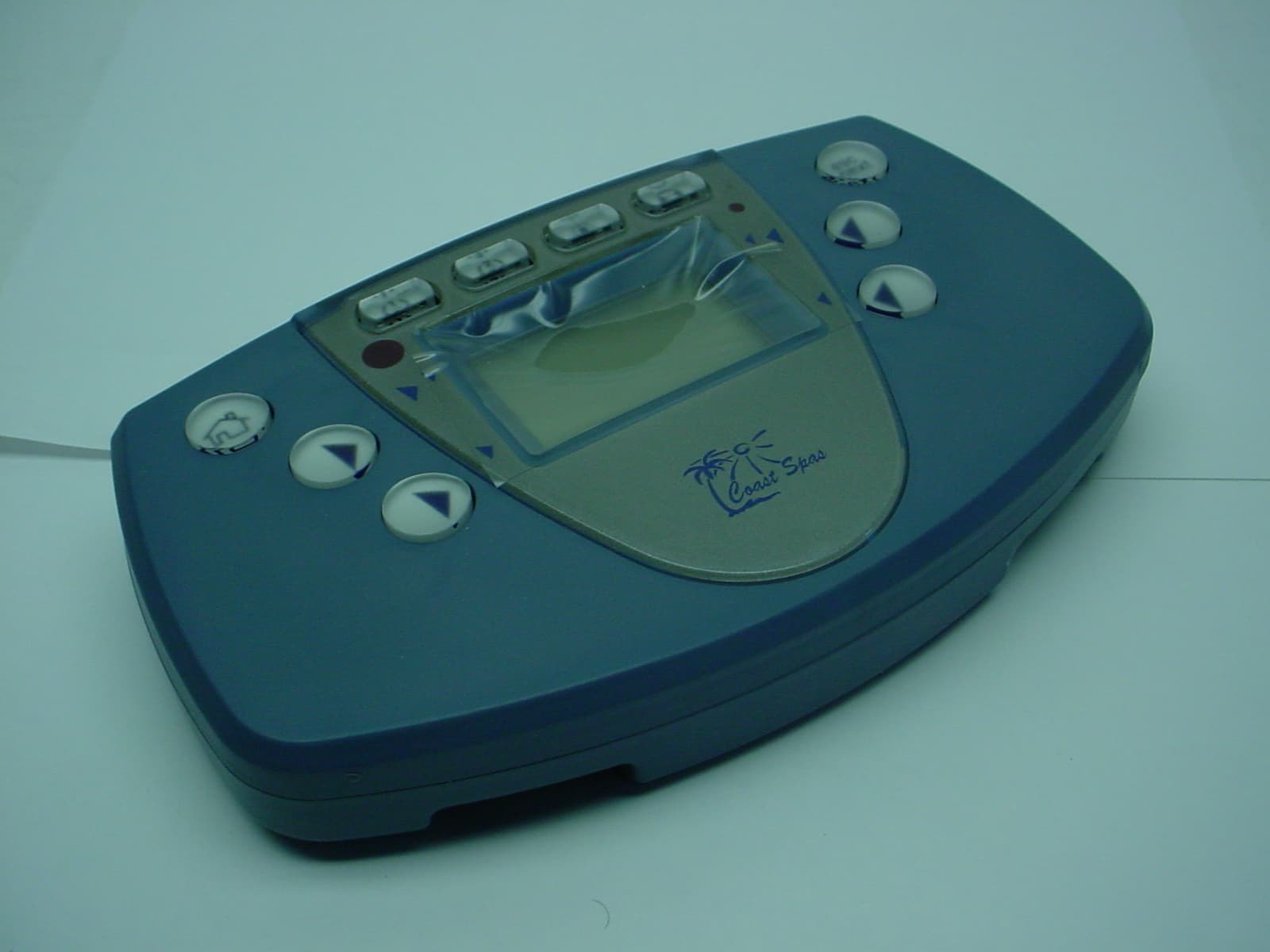
PTT-INK707
May 14, 2006BUOYANT OPERATING SPA SYSTEM (B.O.S.S.)
Equipment Class
DXX - Part 15 Low Power Communication Device TransmitterPTT-RFMR1C
Sep 25, 2005NAVIGATOR
Equipment Class
DXX - Part 15 Low Power Communication Device Transmitter
PTT-RFMT1C
Sep 11, 2005NAVIGATOR
Equipment Class
DXX - Part 15 Low Power Communication Device Transmitter
PTT-TE601
Apr 14, 2005BUOYANT OPERATING SPA SYSTEM (B.O.S.S.)
Equipment Class
DXX - Part 15 Low Power Communication Device Transmitter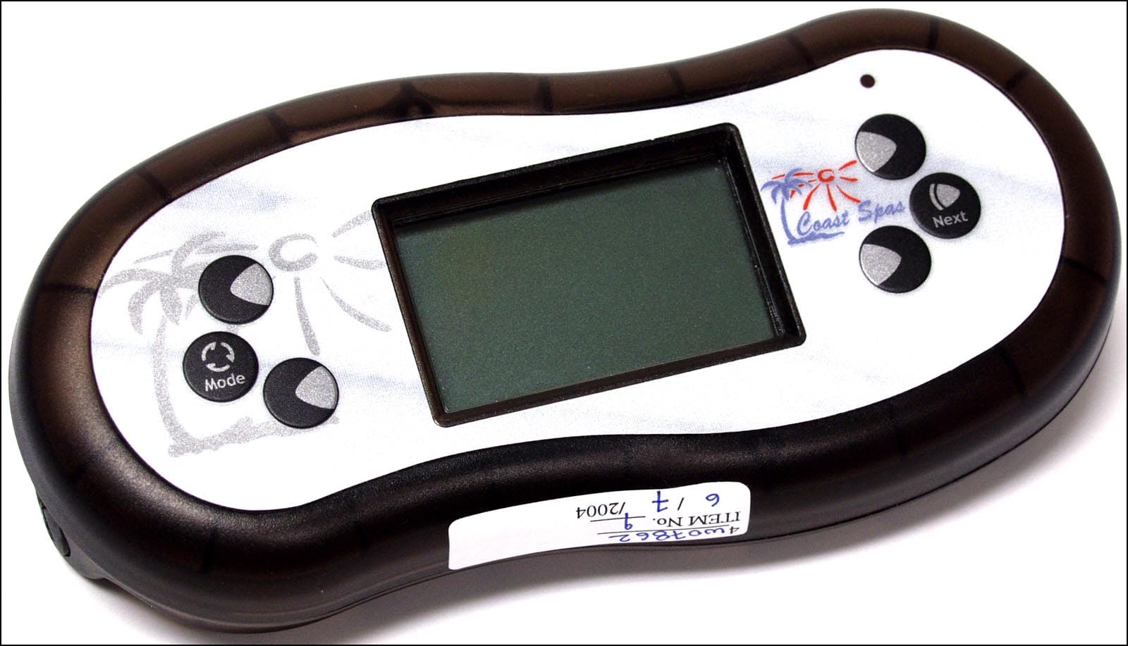
PTTIRFMR-1
Nov 24, 2004IRFMR-1 Remote Control Device
Equipment Class
DXX - Part 15 Low Power Communication Device Transmitter