PU2935-44601-000Hand-Held RF Remote Control
Lowrey Organ Company
Click to zoom
Application Details
- Equipment Class
- DSC - Part 15 Security/Remote Control Transmitter
- Date of Grant
- Sep 28, 2001
- Application Purpose
- Original Equipment
- Date of Application
- Sep 28, 2001
- Equipment Note
- Hand-Held RF Remote Control
- Frequency Range
- 418.00000000 - 418.00000000
- Company
- Lowrey Organ Company
- Country
- United States
Documents & Files
Document Text
Text extracted from the exhibit documents filed with the FCC. Open a document above to read the original.
Users Manual
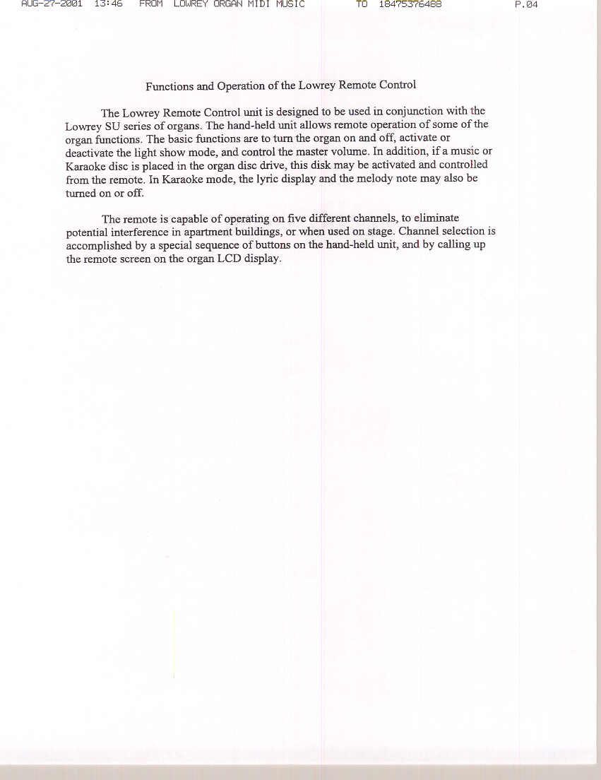
Functions and Operation of the Lowrey Remote Control The Lowrey Remote Control unit is designed to be used in conjunction with the Lowrey SU series of organs. The hand-held unit allows remote operation of some of the organ functions. The basic functions are to turn the organ on and off, activate or deactivate the light show mode, and control the master volume. In addition, if a music or Karaoke disc is placed in the organ disc drive, this disk may be activated and controlled from the remote. In Karaoke mode, the lyric display and the melody note may also be turned on or off. All the buttons on the Remote Control duplicate the functions of like-named buttons on the organ except for the channel selection buttons. 1. On / Off This button turns the organ on and off. It is a toggle type action, the same as the switch on the organ. One push turns the organ on, and the next push turns the organ off. 2. Light Show This button turns on the light show. The organ operates normally while the light show is running. Pressing this button again turns the light show off. 3. SET and Ch 1-5 buttons These buttons set the remote operating channel. They need not be used unless there is a conflict between the remote and some other device. For example, it is possible in a town home or condominium that another Lowrey organ of the same model might be nearby. The organs leave the factory set to channel 0. If another organ or device operating on channel 0 is nearby, there may be interference between the two. In this case, the channel number may be changed. The channel number on the remote and on the organ must match. Instructions for changing the receive channel on the organ appear in the organ operation manual. To change the channel on the remote, use the following procedure: a. Press and hold the SET button until the indicator light starts blinking. b. Press the desired channel button. The light stops blinking and the channel is set. c. To select the default of channel 0, press the SET button again after step a. 4. Play / Pause Pressing this button while the organ is on and a disc is present in the disc drive will start playback of the songs recorded on the disc. Once playback is started, pressing this button again will pause the playback. 5. Stop Pressing this button will stop playback of the disk. The song number will be reset to the first song on the list. 6. << >> Buttons These buttons advance the playback to the next song, or select the previous song. 7. Chain Loop Pressing this button will activate the Chain Loop function, which will cause the first song on the disc to start again after the last song has played. This sequence will continue until the stop button is pressed, or the Chain Loop button is pressed again, in which case the playback will stop after the last song. 8. Lyric If a disc with Karaoke information is being played, pressing this button will cause the lyrics to display on the Information Center screen on the organ, and also on a video monitor if a monitor is connected to the video out jack. Pressing this button again will turn off this feature. 9. Melody When in the Karaoke mode, pressing this button will turn off any instrumental sounds programmed to play the melody. This allows the singer to sing the melody solo, rather than having it be doubled by the orchestration. Pressing this button again turns off this function. 10. Volume (up/down) These buttons raise and lower the master volume. NOTE: Two AA alkaline batteries power The Remote control. Be sure to follow polarity guide molded in battery compartment.
Block Diagram
LOOP ANT. (ON PC) MICRO PROCESSOR (PIC) KEY PAD BATT 2 x 1.5 V. R.F MODULE LED Block Diagram Remote Control Lowrey Organ Company Doug Moore
Cover Letter(s)
FCC ID: PU2935-44601-000 D.L.S. ELECTRONIC SYSTEMS, INC. 1250 Peterson Drive Wheeling, Illinois 60090 FCC Authorization & Evaluation Division 7435 Oakland Mills Road Columbia, Maryland 21045-0429 Gentlemen: We are submitting for Lowrey Organ Company, Inc., a Lowrey Remote Control for SU Series Organs, Model Number 935-044601-000, with a FCC ID: PU2935-44601-000 for a Certification. This unit has been tested and complies to Part 15, Subpart C. If there are any questions in regards to this application, please call D.L.S. Electronic Systems, Inc. at (847) 537 6400. Enclosed you will find a copy of our test report with the information and results of tests that is required under Part 15, Section 15.231. Thank you for your assistance in this matter. Sincerely, Arnom C. Rowe EMC-001375-NE DLS/mm
Cover Letter(s)
Regarding the 5-second requirement, the format of the data sent by the transmitter is as follows: An initial sync bit is sent then the data word then sync etc. until the key is released. A quick blip of the of the handset will cause Sync Data Sync Data. This is so the decoder can compare two words of data. When a key is released, the current Data + Sync is completed. The binary data is transmitted from the handset by PPM. The gap between the leading edge of the pulses is 8mS for a one and 12mS for a zero. The sync bit is 24mS. The data word is broken down into 3 bits for channel number, and 5 bits for key number. A minimum of 2 complete frames of data is sent, so that the receiver can compare them and check for errors. The sequence is repeated as long as the key is held down, so that if the remote is out of range, as it is approaching the receiver the functions will be activated when it is close enough to produce good data. When the key is released, the absolute maximum time the transmitter will send data is 240mS, with 120mS being more common. There are no automatic activations of the transmitter; therefore I believe the transmitter complies with 47 CFR, Part 15.231. Doug Moore
External Photos
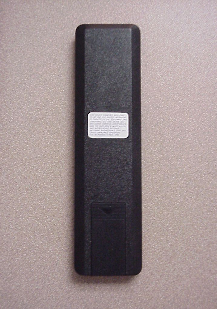
Front of Hand Held Remote Rear of Hand Held Remote Battery Cover removed Batteries removed Inside Covers
Internal Photos
Back Cover removed PC Board - Component Side PC Board - Component Side Close up of RF Module PC Board - Solder Side
Operational Description
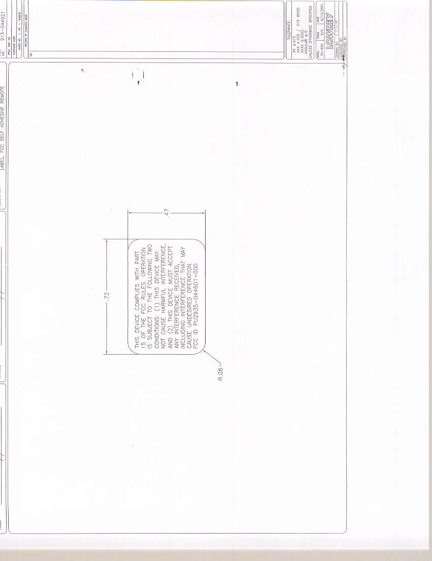
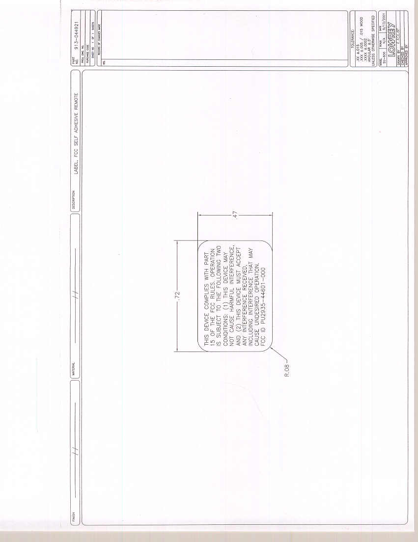
Functions and Operation of the Lowrey Remote Control The Lowrey Remote Control unit is designed to be used in conjunction with the Lowrey SU series of organs. The hand-held unit allows remote operation of some of the organ functions. The basic functions are to turn the organ on and off, activate or deactivate the light show mode, and control the master volume. In addition, if a music or Karaoke disc is placed in the organ disc drive, this disk may be activated and controlled from the remote. In Karaoke mode, the lyric display and the melody note may also be turned on or off. All the buttons on the Remote Control duplicate the functions of like-named buttons on the organ except for the channel selection buttons. 1. On / Off This button turns the organ on and off. It is a toggle type action, the same as the switch on the organ. One push turns the organ on, and the next push turns the organ off. 2. Light Show This button turns on the light show. The organ operates normally while the light show is running. Pressing this button again turns the light show off. 3. SET and Ch 1-5 buttons These buttons set the remote operating channel. They need not be used unless there is a conflict between the remote and some other device. For example, it is possible in a town home or condominium that another Lowrey organ of the same model might be nearby. The organs leave the factory set to channel 0. If another organ or device operating on channel 0 is nearby, there may be interference between the two. In this case, the channel number may be changed. The channel number on the remote and on the organ must match. Instructions for changing the receive channel on the organ appear in the organ operation manual. To change the channel on the remote, use the following procedure: a. Press and hold the SET button until the indicator light starts blinking. b. Press the desired channel button. The light stops blinking and the channel is set. c. To select the default of channel 0, press the SET button again after step a. 4. Play / Pause Pressing this button while the organ is on and a disc is present in the disc drive will start playback of the songs recorded on the disc. Once playback is started, pressing this button again will pause the playback. 5. Stop Pressing this button will stop playback of the disk. The song number will be reset to the first song on the list. 6. << >> Buttons These buttons advance the playback to the next song, or select the previous song. 7. Chain Loop Pressing this button will activate the Chain Loop function, which will cause the first song on the disc to start again after the last song has played. This sequence will continue until the stop button is pressed, or the Chain Loop button is pressed again, in which case the playback will stop after the last song. 8. Lyric If a disc with Karaoke information is being played, pressing this button will cause the lyrics to display on the Information Center screen on the organ, and also on a video monitor if a monitor is connected to the video out jack. Pressing this button again will turn off this feature. 9. Melody When in the Karaoke mode, pressing this button will turn off any instrumental sounds programmed to play the melody. This allows the singer to sing the melody solo, rather than having it be doubled by the orchestration. Pressing this button again turns off this function. 10. Volume (up/down) These buttons raise and lower the master volume. NOTE: Two AA alkaline batteries power The Remote control. Be sure to follow polarity guide molded in battery compartment. FCC Statements: This device complies with part 15 of the FCC Rules. Operation is subject to the following two conditions: (1) This device may not cause harmful interference, and (2) this device must accept any interference received, including interference that may cause undesired operation.
Parts List/Tune Up Info
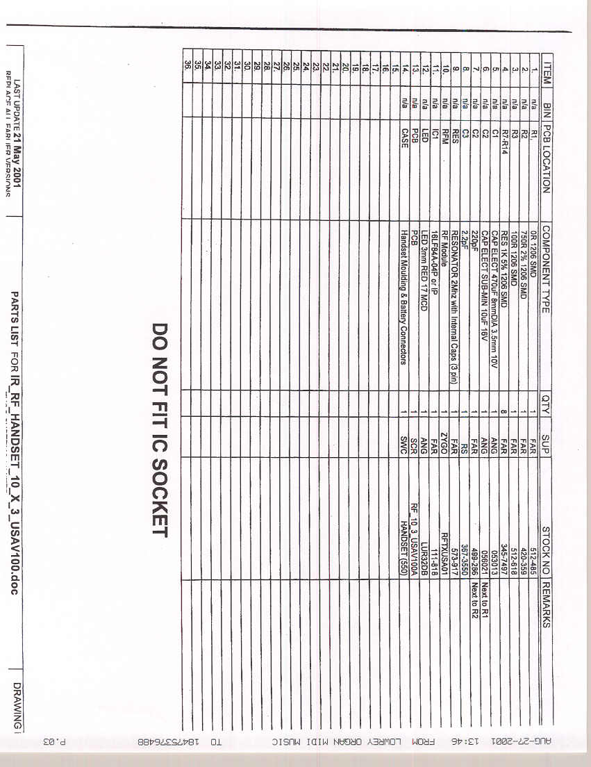
FCC ID: PU2935-44601-000 LIST OF CRYSTAL FREQUENCIES The following is a list of crystal frequencies used in the Transmitter Model No: 9335-044601-000 418 MHz. & 2 MHz
Test Report
EMC Test Services Report No. 9052 1250 Peterson Drive, Wheeling, Illinois 60090, USA TEST SPECIFICATION: FCC "Rules and Regulations", Part 15, Subpart C Sections 15.231 (a-d), 15.207 & 15.205 Intentional Radiators Periodic operation in the band 40.6 – 40.77 MHz & above 70 MHz THE FOLLOWING MEETS THE ABOVE TEST SPECIFICATION Formal Name: Lowrey Remote Control for SU Series Organs Kind of Equipment: Hand-Held RF Remote Control Test Configuration: No external cables. Transmitter FCC ID: PU2935-44601-000 Model Number: 935-044601-000 Serial Number: NA Dates of Test: May 18, 2001 Test Conducted For: Lowrey Organ Company 825 East 26th Street LaGrange Park, Illinois 60526 NOTICE: Please see change information listed inside of this report. This report must not be used by the customer to claim product endorsement by NVLAP or any agency of the United States Government, and it cannot be reproduced (except in full), without the approval of D.L.S. Electronic Systems Inc. Page 1 EMC Test Services Report No. 9052 1250 Peterson Drive, Wheeling, Illinois 60090, USA SIGNATURE PAGE Report Written By: Arnom C. Rowe Test Engineer EMC-001375-NE Report Reviewed by: Jack Prawica Lab Manager Report Approved by: Brian J. Mattson General Manager Company Official: Lowrey Organ Company Page 2 EMC Test Services Report No. 9052 1250 Peterson Drive, Wheeling, Illinois 60090, USA NVLAP Certificate of Accreditation available upon request. Page 3 EMC Test Services Report No. 9052 1250 Peterson Drive, Wheeling, Illinois 60090, USA NVLAP Certificate of Accreditation available upon request. Page 4 EMC Test Services Report No. 9052 1250 Peterson Drive, Wheeling, Illinois 60090, USA NVLAP Certificate of Accreditation available upon request. Page 5 EMC Test Services Report No. 9052 1250 Peterson Drive, Wheeling, Illinois 60090, USA 1. Cover Page i 2. Signature Page ii 3. NBS Certificate of Accreditation iii 6. Table of Contents iv 8. Summary of Test Report 1.0 8. Introduction 2.0 8. Object 3.0 9. Test Set-up 4.0 9. Test Equipment (Bandwidths and Detector Function) 5.0 10. Conducted Emission Measurements 6.0 11. Conducted Emission Data taken during testing 6.0 12. Conducted Emission Graphs taken during testing 6.0 13. Field Strength of Spurious Emission Measurements 7.0 15. Radiated Data taken for Fundamental & Spurious Emissions Measurements 7.0 32. Pulsed Operation (Duty Cycle Correction Factor) 8.0 33. Pulse Operation Graphs taken during testing 8.0 35. Bandwidths 9.0 36. Data taken of Fundamental Frequency & Bandwidths 9.0 38. Restricted Bands 10.0 Page 6 EMC Test Services Report No. 9052 1250 Peterson Drive, Wheeling, Illinois 60090, USA 39. Photo Information and Test Set-Up 11.0 40. Photos Taken During Testing 12.0 43. Change Information 13.0 45. Results of Tests 14.0 45. Conclusion 15.0 46. Equipment List TABLE 1 Page 7 EMC Test Services Report No. 9052 1250 Peterson Drive, Wheeling, Illinois 60090, USA 1.0 SUMMARY OF TEST REPORT It was found that the Lowrey Remote Control for SU Series Organs S/N NA meets the radio interference emission requirements of the FCC "Rules and Regulations", Part 15, Subpart C, Sections 15.231 (a-d), 15.207 and 15.205 for Intentional Radiators operating in the 70 to 900 MHz Frequency Band with periodic operation. This report contains the following number of pages. Text, Data Summary & Charts: 46 pages NOTE: The conducted emissions test was not required because the EUT is powered from a DC power source. It does not have a line cord to plug into the A.C. power line. 2.0 INTRODUCTION On May 18, 2001, a series of radio frequency interference measurements were performed on Hand-Held RF Remote Control, S/N NA. The tests were performed according to the procedures of FCC as stated in MP-1 “FCC Methods of Measurement for determining Compliance of Radio Control and Security Alarm Devices and Associated Receivers”. Tests were performed by personnel of D.L.S. Electronic Systems, Inc. who are responsible to Donald L. Sweeney, Senior EMC Engineer. 3.0 OBJECT The purpose of this series of tests was to determine if the test sample could meet the radio frequency emission requirements of the FCC "Rules and Regulations", Part 15, Subpart C, Sections 15.231 (a-d), 15.207 and 15.205 for Intentional Radiators operating in the 70 to 900 MHz Frequency Band with periodic operation. Page 8 EMC Test Services Report No. 9052 1250 Peterson Drive, Wheeling, Illinois 60090, USA 4.0 TEST SET-UP All conducted emission tests were performed in a shield enclosure or lab at D.L.S. electronic Systems, Inc. The conducted tests were performed with the test item placed on a non-conductive table located in the Test Room. The power line supplied was connected to a dual line impedance stabilization network located on the floor, a ground plane. The networks were constructed per the requirements of the American National Standards Institute, ANSI C63.4-1992, Section 4, (Figure2). The only ground supplied to the unit was through the third wire of the standard power cord when supplied. All radiated emission tests were performed at D.L.S. Electronic Systems, Inc. The radiated tests were made with the test item placed on a non-conductive turntable located in the Test Room with the receive antenna placed three meters from the device under test. The equipment under test was set up according to ANSI C63.4-1992, Section 8, (Figures 9c and 9d). 5.0 TEST EQUIPMENT (Bandwidths and Detector Function) All preliminary data below 1000 MHz was automatically plotted using the Peak or CISPR Detector Functions. This information was then used to determine the frequencies of maximum emissions. Manual measurements were performed on these frequencies using a peak detector function of the Receiver with the bandwidths specified by the FCC. Above 1000 MHz final data was taken using the Peak Detector. Below 1000 MHz final data was taken using the fixed tuned receiver. Plots were made using the Peak Detector, with manual measurements made on the frequencies of interest…
Text truncated - open the document above for the full version.
Test Report
EMC Test Services Report No. 9052 1250 Peterson Drive, Wheeling, Illinois 60090, USA RADIATED DATA TAKEN FOR FUNDAMENTAL EMISSION MEASUREMENTS PART 15.231 Page 1 EMC Test Services Report No. 9052 1250 Peterson Drive, Wheeling, Illinois 60090, USA Page 2 TEST DATE:------------------- May 18, 2001 MANUFACTURER:----------- Zygo Systems Ltd MODEL NO:-------------------- 935-044601-000 S/N:------------------------------- NA CONFIGURATION:----------- NA DCCF:---------------------------- 7.94 TEST SPECIFICATION:FCC "RULES AND REGULATION", PART 15 SUBPART C / SECTION 15.231 TEST EQUIPMENT:Receiver ---- ESI-40 ------- SN 837808/005 Antennas ----- BIA-25 ------- SN 4785 LPA-25 -------SN 4895 TYPE OF TEST: VERTICAL MEASURED AT 3 METERS THE FOLLOWING ARE SIGNIFICANT RADIATED LEVELS FOUND: FREQ METER PRE-AMP ANTENNA TOTAL - IN READING + CABLE FACTOR DCCF LIMIT MARGIN MHz. dBuV dB dB dBuV dB dB 418.0485.95-23.7516.2578.4580.291.84 EMC Test Services Report No. 9052 1250 Peterson Drive, Wheeling, Illinois 60090, USA SUMMARY DATA SHEET OF RADIATED EMISSIONS < 1000 MHz TEST DATE:------------------ - May 18, 2001 MANUFACTURER:----------- Zygo Systems Ltd MODEL NO:-------------------- 935-044601-000 S/N:------------------------------- NA CONFIGURATION:----------- NA DCCF:---------------------------- 7.94 TEST SPECIFICATION:FCC "RULES AND REGULATION", PART 15 SUBPART C / SECTION 15.231 TEST EQUIPMENT:Receiver ---- ESI-40 ------- SN 837808/005 Antennas ----- BIA-25 ------- SN 4785 LPA-25 -------SN 4895 TYPE OF TEST: HORIZONTAL MEASURED AT 3 METERS THE FOLLOWING ARE SIGNIFICANT RADIATED LEVELS FOUND: FREQ METER PRE-AMP ANTENNA TOTAL - IN READING + CABLE FACTOR DCCF LIMIT MARGIN MHz. dBuV dB dB dBuV dB dB 418.0487.28-23.7516.2579.7880.290.51 Page 3
Test Report
EMC Test Services Report No. 9052 1250 Peterson Drive, Wheeling, Illinois 60090, USA RADIATED DATA TAKEN FOR FUNDAMENTAL EMISSION MEASUREMENTS PART 15.231 Page 1 EMC Test Services Report No. 9052 1250 Peterson Drive, Wheeling, Illinois 60090, USA Page 2 TEST DATE:------------------- May 18, 2001 MANUFACTURER:----------- Zygo Systems Ltd MODEL NO:-------------------- 935-044601-000 S/N:------------------------------- NA CONFIGURATION:----------- NA DCCF:---------------------------- 7.94 TEST SPECIFICATION:FCC "RULES AND REGULATION", PART 15 SUBPART C / SECTION 15.231 TEST EQUIPMENT:Receiver ---- ESI-40 ------- SN 837808/005 Antennas ----- BIA-25 ------- SN 4785 LPA-25 -------SN 4895 TYPE OF TEST: VERTICAL MEASURED AT 3 METERS THE FOLLOWING ARE SIGNIFICANT RADIATED LEVELS FOUND: FREQ METER PRE-AMP ANTENNA TOTAL - IN READING + CABLE FACTOR DCCF LIMIT MARGIN MHz. dBuV dB dB dBuV dB dB 418.0485.95-23.7516.2578.4580.291.84 EMC Test Services Report No. 9052 1250 Peterson Drive, Wheeling, Illinois 60090, USA SUMMARY DATA SHEET OF RADIATED EMISSIONS < 1000 MHz TEST DATE:------------------ - May 18, 2001 MANUFACTURER:----------- Zygo Systems Ltd MODEL NO:-------------------- 935-044601-000 S/N:------------------------------- NA CONFIGURATION:----------- NA DCCF:---------------------------- 7.94 TEST SPECIFICATION:FCC "RULES AND REGULATION", PART 15 SUBPART C / SECTION 15.231 TEST EQUIPMENT:Receiver ---- ESI-40 ------- SN 837808/005 Antennas ----- BIA-25 ------- SN 4785 LPA-25 -------SN 4895 TYPE OF TEST: HORIZONTAL MEASURED AT 3 METERS THE FOLLOWING ARE SIGNIFICANT RADIATED LEVELS FOUND: FREQ METER PRE-AMP ANTENNA TOTAL - IN READING + CABLE FACTOR DCCF LIMIT MARGIN MHz. dBuV dB dB dBuV dB dB 418.0487.28-23.7516.2579.7880.290.51 Page 3
Contact Information
Applicant
Satoshi Takada(Division Manager)
Technical Contact
D.L.S ElectronicsArnom Rowe
[email protected]847 537 6400
1250 Peterson Drive · Wheeling, Illinois · United States
Test Firm
DLS Electronic Systems, Inc.William Stumpf
Technical Specifications
| # | Rule Parts | Frequency Range | Power Output | Tolerance |
|---|---|---|---|---|
| 1 | 15.231 | 418 MHz - 418 MHz | - | 0.0050000000 % |