Click to zoom
Application Details
- Equipment Class
- DSS - Part 15 Spread Spectrum Transmitter
- Date of Grant
- Sep 16, 2007
- Application Purpose
- Original Equipment
- Date of Application
- Sep 16, 2007
- Equipment Note
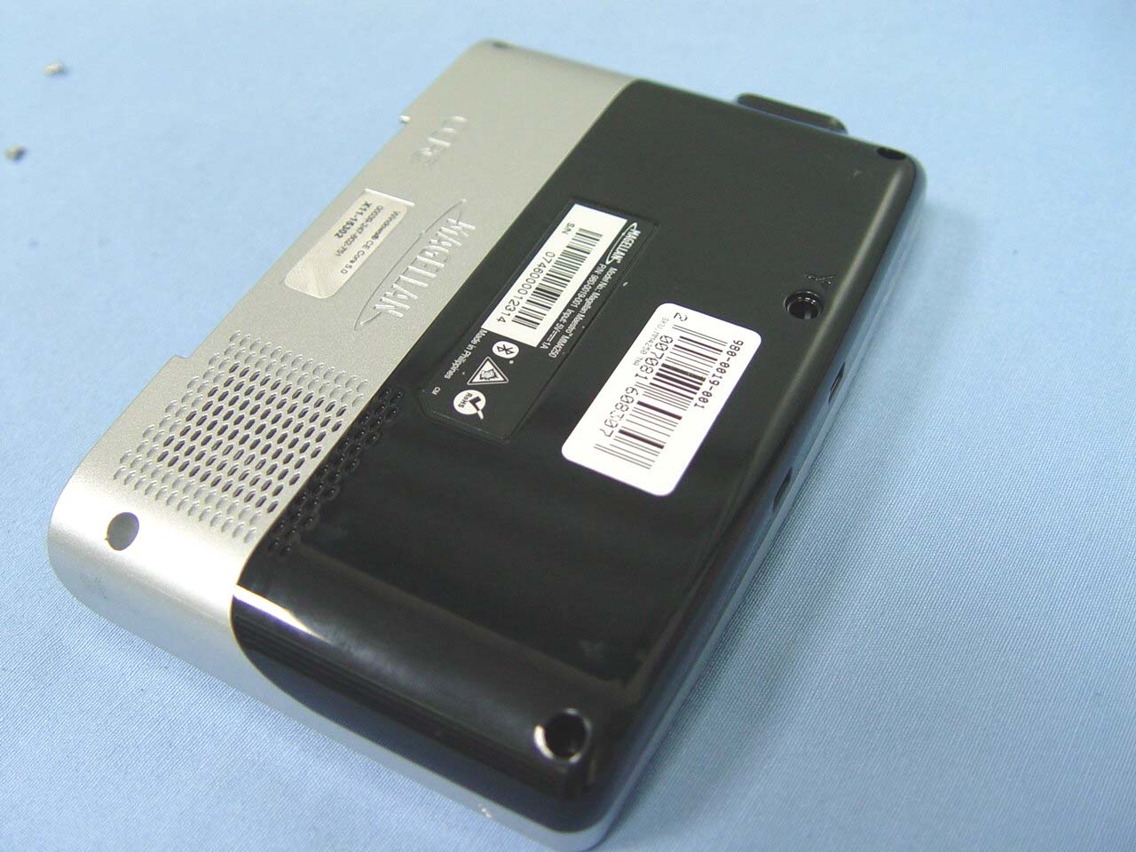
- GPS TRITON
- Frequency Range
- 2402.00000000 - 2480.00000000
- Company
- Wistron Corporation
- Country
- Taiwan
Documents & Files
Select a file to view