PVD-MKA381WIRELESS MICROPHONE
Shenzhen JWL Electronics Co., Ltd.
Click to zoom
Application Details
- Equipment Class
- TNF - Licensed Non-Broadcast Transmitter Held to Face
- Date of Grant
- Apr 25, 2005
- Application Purpose
- Original Equipment
- Date of Application
- Apr 25, 2005
- Equipment Note
- WIRELESS MICROPHONE
- Frequency Range
- 171.04500000 - 171.04500000
- Country
- China
Documents & Files
Document Text
Text extracted from the exhibit documents filed with the FCC. Open a document above to read the original.
Users Manual
1 SAFETY PRECAUTIONS FCC INFORMATION Warning: Modifying, tampering and/or adjusting this unit or replacement of any transmitter component (crystal, semiconductor, etc.) in this unit could result in a violation of the rules. FCC NOTICE This wireless microphone system complies with Part 90 of FCC Rules. There are two frequencies available for the system. You must get a license for each frequency you plan to use before you use the system (one license can include both frequencies). Visit http://wireless.fcc.gov/uls/ to access the license online or phone the nearest FCC offices and contact them to get the necessary application. Licensing depends on how you will use the system. RF EXPOSURE This wireless microphone contains a low power transmitter. When the power is on, it sends out radio frequency (RF) signals. ln August 1996, the Federal Communications Commissions (FCC) adopted RF exposure guidelines with safety levels for wireless devices. IMPORTANT NOTE: To adhere to the FCC RF exposure compliance requirements, no change to the antenna or the unit is permitted. Any change to the antenna or the unit could result in the system exceeding the RF exposure requirements. IMPORTANT To maintain compliance with the FCC's RF exposure guidelines hold the transmitter and antenna at least 1 inch (2.5 centimeters) from your face and speak in a normal voice, with the antenna pointed up and away from your face. Ensure that the antenna is at least 1 inch (2.5 centimeters) from your body when using your wireless microphone. Use only the supplied antenna. Unauthorized antennas, modifications or attachments could damage the transmitter and may violate FCC regulations. Warning: Changes or modifications to this unit not expressly approved by the party responsible for compliance could void the user's authority to operate the equipment. NOTE: This equipment has been tested and found to comply with the limits for a Class B digital device, pursuant to Part 15 of the FCC Rules. These limits are designed to provide reasonable protection against harmful interference in a residential installation. This equipment generates, uses and can radiate radio frequency energy and, if not installed and used in accordance with the instructions, may cause harmful interference to radio communications. However, there is no guarantee that interference will not occur in a particular installation. If this equipment does cause harmful interference to radio or television reception, which can be determined by turning the equipment off and on, the user is encouraged to try to correct the interference by one or more of the following measures: • Reorient or relocate the receiving antenna. • Increase the separation between the equipment and receiver. • Connect the equipment into an outlet on a circuit different from that to which the receiver is connected. •Consult the dealer or an experienced radio/TV technician for help. PLEASE KEEP ALL PACKAGING MATERIAL FOR AT LEAST 90 DAYS IN CASE YOU NEED TO RETURN THIS PRODUCT TO YOUR PLACE OF PURCHASE OR MEMOREX. 2 SAFETY PRECAUTIONS (CONTINUED) 3 LOCATION OF CONTROLS 231 456 8109 7 1. POWER Indicator 2. Microphone ON/STANDBY/OFF Switch 3. Battery Compartment 4. Line OUT Jack 5. DC 9V Jack z 6. POWER ON Indicator 7. Microphone ON Indicator 8. POWER ON/OFF Switch 9. Battery Compartment (Bottom of Receiver) 10. Antenna MICROPHONE RECEIVER FRONT RECEIVER SIDE 4 INSTALLATION REPLACING THE BATTERIES If the sound quality starts to become poor or the receiving distance has shortened, replace the batteries in the microphone and the receiver as follows: INSTALLING THE BATTERY INTO THE MICROPHONE Remove the battery cover at the bottom of the microphone by twisting it counterclockwise. 1 Insert one 9V battery, making sure to observe the correct polarity (+/–). Twist the battery cover clockwise to put it back on. 2 INSTALLING THE BATTERY INTO THE RECEIVER Remove the battery cover by sliding it off. To prevent the possibility of 1 Insert a 9V size battery (not included) to the connector inside the battery compartment. Slide the 2 DC JACK to an AC outlet having AC 120V, 60Hz only. Plug the small end into the DC 9V jack on the side of the unit and connect the other end into the AC outlet. The batteries will be disconnected when the AC adapter is connected. + - BATTERY PRECAUTIONS Follow these precautions when using batteries in this device: 1. Use only the size and type of batteries specified. 2. Be sure to follow the correct polarity when installing the batteries as indicated in the battery compartment(s). Reversed batteries may cause damage to the device. 3. If the device is not to be used for a long period of time, remove the batteries to prevent damage or injury from possible battery leakage. 4. Do not try to recharge batteries not intended to be recharged; they can overheat and rupture. (Follow battery manufacturer’s directions.) losing the cover, it cannot be removed. To use the receiver with AC power, connect the AC adapter (included) battery cover back into place. 5 NOTES: • When done using the receiver, slide the POWER switch to the OFF position; the red POWER indicator will go out. • If your microphone is not to be used for a long period of time, remove the batteries in the microphone and the receiver. • If the microphone is out of range (microphone too far away from the receiver) the green Microphone ON indicator on the receiver will turn of f and the microphone will be muted. OPERATION Insert the large end of the cord into the Microphone jack on the unit you are connecting this wireless microphone to and the small end into the Line OUT jack on the receiver. 1 Slide the Microphone ON/STANDBY/ OFFswitch to the ON position; the POWER indicator on the microphone will light. 2 Slide the Receiver’s POWER switch to the ON position; the red POWER indicator on the receiver will light. If the microphone is on, the green Microphone ON indicator on the receiver will also light. Raise the antenna for best reception and …
Text truncated - open the document above for the full version.
External Photos
Applicant: Shen Zhen JWL Electronic Co., Ltd. FCC ID: PVD-MKA381 Tx EUT view
ID Label/Location Info
Applicant: Shen Zhen JWL Electronic Co., Ltd. FCC ID: PVD-MKA381 This device complies with Part 90 of the FCC Rules. Proposed Label Location on EUT EUT Bottom View/Proposed FCC ID Location FCC ID: PVD-MKA381
Internal Photos
Applicant: Shen Zhen JWL Electronic Co., Ltd. FCC ID: PVD-MKA381 Tx EUT inside whole view Tx Main board component side Tx Main board solder side
Operational Description
Applicant: Shen Zhen JWL Electronic Co., Ltd. FCC ID: PVD-MKA381 Operational Description 1. Audio 1) MIC AMPVT1) This amplifiers the voice signal of 50Hz~15KHz by about 20dB and makes pre-emphasis features of 50us. 2) Regulator (N1) RF part being supplied power from 9V Battery. 2. RF 1) Oscillator (VT3) This is a transmitting carrier oscillator that modulates the voice signal supplied for Audio to frequency and then oscillates third-time overtone and becomes standard oscillation for RF Carrier. 2) MULTI (VT4) This multiplies the frequency oscillated from VT3.(FREQ: multiplied frequency) 3) MULTI (VT5) This also multiplies the frequency multiplied from VT4.(FREQ: multiplied frequency).
Parts List/Tune Up Info
Applicant: Shen Zhen JWL Electronic Co., Ltd. FCC ID: PVD-MKA381 Components List of MKA381 Transmitter Page: 1 of 2 C1 33p/0603 Chip Capacitor C10 4.7n/0603 Chip Capacitor C11 1u/16V/4x7 Electrolytic Capacitor C12 1u/0603 Chip Capacitor C13 1u/0603 Chip Capacitor C14 10n/0603 Chip Capacitor C15 10n/0603 Chip Capacitor C16 47p/0603 Chip Capacitor C17 33p/0603 Chip Capacitor C18 51p/0603 Chip Capacitor C19 68p/0603 Chip Capacitor C20 0.5p/0603 Chip Capacitor C21 1n/0603 Chip Capacitor C22 100p/0603 Chip Capacitor C23 62p/0603 Chip Capacitor C24 3.9p/0603 Chip Capacitor C25 1n/0603 Chip Capacitor C26 0.5p/0603 Chip Capacitor C27 6.2p/0603 Chip Capacitor C28 220p/0603 Chip Capacitor C29 47p/0603 Chip Capacitor C3 4.7u/16V/4x7 Chip Capacitor C30 100p/0603 Chip Capacitor C31 13p/0603 Chip Capacitor C32 3.9p/0603 Chip Capacitor C33 30p Trimmer capacitor C34 10p/0603 Chip Capacitor C35 10n/0603 Chip Capacitor C36 4.7u/16V/4x7 Electrolytic Capacitor C4 33p/0603 Chip Capacitor C5 1n/0603 Chip Capacitor C6 47u/16V/4x7 Electrolytic Capacitor C7 1u/16V/4x7 Electrolytic Capacitor C9 33p/0603 Chip Capacitor L1 SJ06 Variable Coil L2 5mm Jump Wire L3 7KN20 Transformer L4 SJ04(cu) Variable Coil L5 0.6/3.5/3.5T Coil L7 0.6/3.5/4.5T Coil Components List of MKA381 Transmitter Page: 2 of 2 L8 2.2uH Fixed Inductor L9 2.2uH Fixed Inductor N1 78L05 Manostat R10 75k/0603 Chip Resistor R12 4.7k/0603 Chip Resistor R13 10k/0603 Chip Resistor R14 5.6k/0603 Chip Resistor R15 510/0603 Chip Resistor R16 10k/0603 Chip Resistor R17 2.2k/0603 Chip Resistor R18 10k/0603 Chip Resistor R19 33k/0603 Chip Resistor R20 1k/0603 Chip Resistor R21 100/0603 Chip Resistor R22 2.2k/0603 Chip Resistor R23 680/0603 Chip Resistor R24 680/0603 Chip Resistor R25 100k/0603 Chip Resistor R3 1k/0603 Chip Resistor R5 1k/0603 Chip Resistor R6 220k/0603 Chip Resistor R9 22k/0603 Chip Resistor RP1 B50k Potentiometer SW1 SS-23D03 Switch VD1 MMBDN4148 Diode VD2 2R53HD*7-07 Φ3.0 Red LED VD3 BB134 Varactor VT1 2SC1623 Transistor VT3 2SC2714 Transistor VT4 2SC2714 Transistor VT5 PBR951 Transistor X1 T171.045MHz Crystal XS1 2.0*2PIN Connecter
Parts List/Tune Up Info
Applicant: Shen Zhen JWL Electronic Co., Ltd. FCC ID: PVD-MKA381 Tune-UP Procedure 1. Input power to this device and check the voltage and the current consumption: 9V ±1V,15~30mA. 2. After connecting the Antenna terminal to spectrum Analyzer, adjust L3 for maximum power of the fundamental frequency and minimum power of the spurious frequency. 3. Adjust L4 for minimum power of spurious frequency. 4. Adjust C33 for maximum output power. 5. Connect the Antenna terminal to Frequency Counter and then adjust L1 for the proper frequency . 6. Apply 100mVp-p of audio at 400Hz to terminal of this device with Audio signal Generator and adjust RP1 to modulate to 15KHz.
Schematics
JWL ELECTRONIC CO.,LTD 16-Mar-2005 Printer Date: ADDRESS: TITLE: MKA381-Tx(JWL31030) V2.0 REVISION: 11 Sheet: ShenZhen China DengQiang DESIGN: APPROVE: YouXiaoJun X1 14.25375MHz C17 33p C18 51p C16 47p C1968p R1310k R14 5.6k VD3 BB134 VT3 2SC2714 C5 1n VT5 PBR951 C14 10n C20 0.5p R5 1k R6220k VT2 2SC1623 C131u C9 33p MIC C6 47u SW1 C4 33p C1 33p MKA381 Transmitter Schematic VT4 2SC2714 L1SJ06 R17 2.2k R24 680ohm C30 100p L7 φ 4.0/ φ 0.6/4.5T N178L05 C276.2p C121u C21 10n C3 4.7u/16V RP1 B50k R3 1k C36 4.7u/16V C7 1u/16V C11 1u C10 4.7n C260.5p R922k R10 75k R16 10k SW1 L3 7KN20 R1810kR1933k R201k C22 100p L4 SJ04(cu) TP1 C23 62p C24 3.9p R23680R222.2k TP2 VD1MMBD4148 R124.7k L5 φ3.5/φ0.6/3.5T C33 20p R15 510 L92.2uH C3410p C3510n L82.2uH VD2RD_LED R25100k C15 10n R21100 C251n C28220p C68p C323.9p BT19V C3113p C2947p
Test Report
The test report consists 23 pages in total. It may be duplicated completely for legal use with the allowance of the applicant. It shall not be reproduced except in full, without the written approval of Ke Mei Ou Laboratory Corporation. The test result in the report only applied to the tested sample. FCC TEST REPORT Under FCC Part 90.265(b) Prepared For: Shen Zhen JWL Electronic Co., Ltd. Room B-OP, 27/F Window to Modernization Building N. Hua Qiang Road, Futian District Shenzhen, Guangdong, China April 18, 2005 FCC ID: PVD-MKA381 EUT: Wireless Microphone Model: MKA381 Report Type: Original Report Test Engineer: Peter Lin Test Date: March 26, 2005 Review By: Apollo Liu / Manager Ke Mei Ou Laboratory Co., Ltd. 7A, Jiaxiangge, Jiahuixincheng, No.3027, Shennan Rd., Futian, Shenzhen, Guangdong, P.R.China. Zip Code: 518033 Tel: + 86 755 83642690 Fax: + 86 755 83297077 www.kmolab.com FEDERAL COMMUNICATIONS COMMISSION Registration Number: 125782 INDUSTRY CANADA Registration Number: IC4986 Shen Zhen JWL Electronic Co., Ltd. FCC ID: PVD-MKA381 FCC ID Report Report #: KSZ2005022802J02 Page 2 of 23 TABLE OF CONTENTS 1. General Information....................................................................................................................................................3 1. 1 Notes......................................................................................................................................................................3 1. 2 Testing Laboratory..................................................................................................................................................3 1. 3 Details of Applicant................................................................................................................................................3 1. 4 Application Details..................................................................................................................................................3 1. 5 Test Item.................................................................................................................................................................3 1. 6 Test Standards.........................................................................................................................................................3 2. Technical Test...............................................................................................................................................................4 2. 1 Summary of Test Results.........................................................................................................................................4 3. EUT Modifications.......................................................................................................................................................4 4. Conducted Power Line Test.........................................................................................................................................5 4. 1 Test Equipment.......................................................................................................................................................5 4. 2 Test Procedure........................................................................................................................................................5 4. 3 Test Setup...............................................................................................................................................................5 4. 4 Configuration of The EUT.......................................................................................................................................6 4. 5 EUT Operating Condition........................................................................................................................................7 4. 6 Conducted Power Line Emission Limits..................................................................................................................7 4. 7 Conducted Power Line Test Result...........................................................................................................................7 5. Output Power Measurement........................................................................................................................................8 5. 1 Test Equipment.......................................................................................................................................................8 5. 2 Test Procedure........................................................................................................................................................8 5. 3 Test Setup...............................................................................................................................................................8 5. 4 Configuration of The EUT.......................................................................................................................................9 5. 5 EUT Operating Condition........................................................................................................................................9 5. 6 Rules and Specification Limits................................................................................................................................9 5. 7 Output Power Test Result........................................................................................................................................9 5. 8 Result Calculation...................................................................................................................................................9 6. Modulation Characteristics.......................................................................................................................................10 6. 1 Test Equipment..................................................................................................…
Text truncated - open the document above for the full version.
Contact Information
Applicant
James Wang(General Manager)
Test Firm
Ke Mei Ou Laboratory Co., Ltd.Apollo Liu
Technical Specifications
| # | Rule Parts | Frequency Range | Power Output | Emission | Tolerance |
|---|---|---|---|---|---|
| 1 | 90.265 | 171.045 MHz - 171.045 MHz | 230.00 µW | 30K6F3E | 0.0100000000 % |
Other Applications from Shenzhen JWL Electronics Co., Ltd.

PVDHT-16D
May 26, 2010WIRELESS MICROPHONE TRANSMITTER
Equipment Class
TBF - Licensed Broadcast Transmitter Held to Face
PVDBT-16B
May 19, 2010WIRELESS MICROPHONE TRANSMITTER
Equipment Class
TBT - Licensed Broadcast Transmitter Worn on Body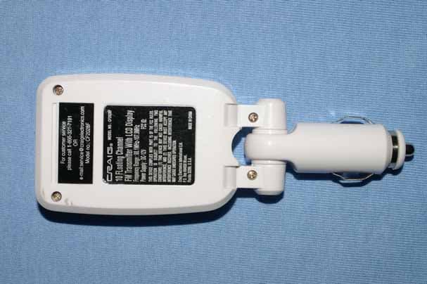
PVDCF2028F
Apr 05, 2006FM Transmitter
Equipment Class
DXX - Part 15 Low Power Communication Device Transmitter
PVDHT-U20
Jan 23, 2006Wireless Microphone
Equipment Class
TNF - Licensed Non-Broadcast Transmitter Held to Face
PVDHT-V20
Jan 22, 2006Wireless Microphone
Equipment Class
TNF - Licensed Non-Broadcast Transmitter Held to Face