PVDWM-737Wireless Microphone
Shenzhen JWL Electronics Co., Ltd.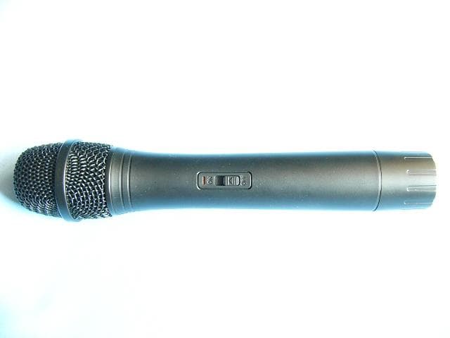
Click to zoom
Application Details
- Equipment Class
- TBF - Licensed Broadcast Transmitter Held to Face
- Date of Grant
- Mar 04, 2004
- Application Purpose
- Original Equipment
- Date of Application
- Mar 04, 2004
- Equipment Note
- Wireless Microphone
- Frequency Range
- 176.30000000 - 201.60000000
- Country
- China
Documents & Files
Document Text
Text extracted from the exhibit documents filed with the FCC. Open a document above to read the original.
Users Manual
AVERTISSEMENT PRECAUTIONS MODEL NO : WM-737 Thank you for buying our company product. Please read through these operation instructions. So you will know how to operate your model properly. After you reading it, put them away in a safe place for future reference. - To prevent fire or shock hazard, do not expose the unit to rain or moisture. - To avoid electrical shock, do not open the cabinet. - Refer servicing to qualified personnel only. - Do not drop or give any physical shocks to the wireless microphone. - Do not use the system where it may be subjected to : direct or indirect sunlight, excessive heat from radiators or other heat sources, excessive dust or humidity, mechanical or other vibrations. - Should any liquid or external object fall into the unit, disconnect the unit from the power source and have it checked by qualified personnel before operating it any. - If you have any questions or problems concerning this system which are not covered in this manual, please consult the nearest company dealer. - Be sure to bring the wireless microphones and thereceiver (the whole system) to the company dealer when requiring repair work. OPERATION INATRUCTIONS WIRELESS MICROPHONE SYSTEM Applicant: Shen Zhen JWL Electronic Co., Ltd. FCC ID: PVDWM-737 OPERATION: 1. Remove the battery cover of handheld or body-pack transmirrer, put a 9 volt battery in she compartment as the polarities and then close the cover. (if a body-pack transmitter is used, you should put a 3.5 plug of a headset or tie-clip microphone into the 3.5 jack on the transmitter.) 2. Connect the matched adapter to the AC power and plug the DC plug at the other end into the DC jack on the receiver. 3. Put one end or the matched connecting wire 6.3MO.(P)/6.3MO.(P) to the mic jack on the amplifier,and the other end to the 6.35(J) jack on the receiver.Soitch on the transmitter and receiver,the indicator light are flkshing,You can adjust the volume kf the amplifier as you like, then the system is working. Please take time to read this manual, before asking for after service. And checking follow points. If it also have unusual thing, please contact with purchasing store. We are sincerely to serve for you. 1. Before connecting and operating the unit, check the voltage setting conformed to the voltage available in your area. 2. If the LED indicator is still on light that means power suppy is in need or replacement. Please replace a new 9V battery and be sure that polarity (+)(-) or battery is connected properly. 3. Signal dropouts and noise may be suddenly encountered by interuption form outside, too long distance between microphone and receiver or battery in low power. In such case, adjust receiver antenna or change new battery. 4. Do not drop the microphone on a hard concrete floor, not strike the microphone head front with a fist or fingers, nor blow a breath strongely into the microphone head front. 5. Remove the battery from microphone if it doesn’t use during a long time. This will prevent any damage caused by a defective “leaking” battery. TROUBLE SHOOTING: OPERATION: OPERATION: The wireless microphone is not turned on. Turn on the wireless microphone The microphone receiver is not turned on. Turn on the microphone receiver and the connected AV equipment The on air Indicator does Not light The microphone receiver is not connected Properly. Turn on the microphone receiver and the connected AV equipment The battery in the wireliss microphone is weak. Replace the battery The microphone receiver is not Turned on. Turn on the microphone receiver and the connected AV equipment The connected AV equipment is not Turned on. Turn on the AV equipment No sound The speakers/headphones, are not connected to the AV equipment. Connect the speakers/headphones The battery in the wireless microphone is work. Replace the battey The sound is ditorted The AUDIO OUT on the receiver is not set correctly. See the ‘‘PARTS IDENTIFICATION’’ in this manual and set it correcty The distance between the wireless Mircrophone and speakers are too Close. Move the wireless microphone away from the speakers or change the direction of the microphone A howling noise heoard from the speakes The battery in the wireless Microphone is weak. Replace the battery OVERALL SYSTEM Carrier Frequency Range 160 to 270 MHz, VHF HIGH BAND. Frequency Stability +/-0.005% with quartz controlled. Maximum Deviation Range +/-15KHz. With limiting compressor Frequency Response 100Hz to 15KHz S/N Ratio Better than 100dB.(A). T.H.D Less the 0.5% Audio Dynamic Range Over 100dB. Over 188dB with limiting Service Areas 30 meters Receiving system Dual channels fixed frequency by quart S/N Ratio Over 108dB at 15KHz deviation Image and Spurious 80 dB minimum Rejection AC 230V/DC 12V Power supply Techonology of U.S.A TROUBLE SHOOTING GUIDE TROUBLE SHOOTING GUIDE
Block Diagram
Applicant: Shen Zhen JWL Electronic Co., Ltd. FCC ID: PVDWM-737 176.3MHz~201.6MHz
External Photos
Applicant: Shen Zhen JWL Electronic Co., Ltd. FCC ID: PVDWM-737 EUT view
ID Label/Location Info
Applicant: Shen Zhen JWL Electronic Co., Ltd. FCC ID: PVDWM-737 This device complies with Part 74 of the FCC Rules. Proposed Label Location on EUT EUT Bottom View/Proposed FCC ID Location FCC ID: PVDWM-737
Internal Photos
Applicant: Shen Zhen JWL Electronic Co., Ltd. FCC ID: PVDWM-737 EUT inside whole view Main board component side Main board solder side
Operational Description
Applicant: Shen Zhen JWL Electronic Co., Ltd. FCC ID: PVDWM-737 Operational Description 1. Audio 1) MIC AMP(N1) This amplifiers the voice signal of 50Hz~15KHz by about 20dB and makes pre-emphasis features of 50us. 2) Regulator (N3) This makes standard voltage for MIC AMP and RF part being supplied power from 9V Battery. 3) Adjust the Distortion Adjust the Distortion with semi-volume can minimize the noise of pre-emphasis compressor and MIC AMP. 2. RF 1) Oscillator (VT3) This is a transmitting carrier oscillator that modulates the voice signal supplied for Audio to frequency and then oscillates third-time overtone and becomes standard oscillation for RF Carrier. 2) MULTI (VT4) This multiplies the frequency oscillated from Q1.(FREQ: multiplied freq2uency) 3) MULTI (VT5) This also multiplies the frequency multiplied in Q2.(FREQ: multiplied frequency) 4) Buffer This doesn’t make the antenna affect the internal circuit when connecting the antenna and final carrier multiplied from VT6.
Parts List/Tune Up Info
Applicant: Shen Zhen JWL Electronic Co., Ltd. FCC ID: PVDWM-737 COMPONENTS LIST OF WM-737 TRANSMITTER NO. Name Specification Quantity/set A Chip resistor 100Ω/0603 1 1. 220Ω/0603 1 2. 470Ω/0603 1 3. 680Ω/0603 2 4. 1kΩ/0603 3 5. 1.5kΩ/0603 1 6. 2.2kΩ/0603 3 7. 5.6kΩ/0603 3 8. 10kΩ/0603 8 9. 22kΩ/0603 2 10. 33kΩ/0603 4 11. 47kΩ/0603 3 12. 75kΩ/0603 1 13. 100kΩ/0603 2 14. 180kΩ/0603 1 15. 220kΩ/0603 1 16. Chip capacitor 0.5pF/0603 1 17. 0.5pF/0805 1 18. 3pF/0603 1 19. 8.2pF/0603 1 20. 10pF/0603 3 21. 10pF/0805 1 22. 12pF/0603 1 23. 15pF/0603 1 24. 15pF/0805 1 25. 18pF/0603 1 26. 20pF/0805 1 27. 51pF/0603 4 28. 62pF/0805 1 29. 100pF/0603 2 30. 0.22uF/0603 2 31. 1nF/0603 2 32. 10nF/0603 11 33. Potentiometer 50kΩ 1 34. Electrolytic capacitor 1uF/25v4×7 1 35. 2.2uF/25v4×7 4 36. 22uF/25v4×7 1 37. 100uF/25v6.3×11 2 38. Trimmer capacitor 30pF 2 39. Fix inductance AL0307-2R2J(2.2uH) 3 40. Variable coil SJ04(7×7)50nH 2 41. SJ04T(7×7)50nH 1 42. SJ05T(7×7)130nH 1 43. SJ06(7×7)7.7uH 1 44. Coil 3.5/0.6/3.5T 2 45. 4/0.6/4.5T 2 46. 4/0.6/6.5T 1 47. Crystal transmitter 14.6937MHz(176.3) 1 48. Regulator 5002L(TO-92B) 1 49. Audion 2SC2714(SOT-23) 2 50. 2SC9012(SOT-23) 1 51. 2SC9018(SOT-23) 2 52. 2SC1623(SOT-23) 1 53. Diode MMBD4148(SOT-23) 1 54. IC 4558(SO-8) 1 55. XC61CN37 1 56. Jump wire 5mm 1
Parts List/Tune Up Info
Applicant: Shen Zhen JWL Electronic Co., Ltd. FCC ID: PVDWM-737 Tune-UP Procedure 1. Input power to this device and check the voltage and the current consumption: 9V ±1V,25~35mA. 2. After connecting the Antenna terminal to spectrum Analyzer, adjust L3 and L4 for maximum power of the fundamental frequency and minimum power of the spurious frequency. 3. Adjust L5and L6 for minimum power of spurious frequency. 4. Adjust C42 and C44 for maximum output power. 5. Connect the Antenna terminal to Frequency Counter and then adjust L1 for the proper frequency . 6. Apply 200mVp-p of audio at 400Hz to terminal of this device with Audio signal Generator and adjust RP1 to modulate to 15KHz.
Schematics
wm-737 transmitter (3048x1990x2 gif)
Test Report
The test report consists 30 pages in total. It may be duplicated completely for legal use with the allowance of the applicant. It shall not be reproduced except in full, without the written approval of Ke Mei Ou Laboratory Corporation. The test result in the report only applied to the tested sample. FCC TEST REPORT Under FCC Part 74 Subpart H, Prepared For: Shen Zhen JWL Electronic Co., Ltd. Room B-OP, 27/F Window to Modernization Building N. Hua Qiang Road, Futian District Shenzhen, Guangdong, China February 2, 2004 FCC ID: PVDWM-737 EUT: Wireless Microphone Model: WM-737 Report Type: Original Report Test Engineer: Peter Lin Test Date: January 19, 2004 Review By: Apollo Liu / Manager FEDERAL COMMUNICATIONS COMMISSION Registration Number: 125782 Ke Mei Ou Laboratory Co., Ltd. 7A, Jiaxiangge, Jiahuixincheng, No.3027, Shennan Rd., Futian, Shenzhen, Guangdong, P.R.China. Zip Code: 518033 Tel: + 86 755 83642690 Fax: + 86 755 83297077 www.kmolab.com Shen Zhen JWL Electronic Co., Ltd. FCC ID: PVDWM-737 FCC ID Report Report #: KSZ2003112903J Page 2 of 30 TABLE OF CONTENTS 1. General Information...........................................................................................................................................................3 1. 1 Notes...............................................................................................................................................................................3 1. 2 Testing Laboratory..........................................................................................................................................................3 1. 3 Details of Applicant........................................................................................................................................................3 1. 4 Application Details.........................................................................................................................................................3 1. 5 Test Item.........................................................................................................................................................................3 1. 6 Test Standards.................................................................................................................................................................4 2. Technical Test.......................................................................................................................................................................5 2. 1 Summary of Test Results................................................................................................................................................5 3. EUT Modifications..............................................................................................................................................................6 4. Conducted Power Line Test................................................................................................................................................7 4. 1 Test Equipment...............................................................................................................................................................7 4. 2 Test Procedure................................................................................................................................................................7 4. 3 Test Setup.......................................................................................................................................................................7 4. 4 Configuration of The EUT..............................................................................................................................................8 4. 5 EUT Operating Condition...............................................................................................................................................9 4. 6 Conducted Power Line Emission Limits........................................................................................................................9 4. 7 Conducted Power Line Test Result...............................................................................................................................10 5. Output Power Measurement..............................................................................................................................................11 5. 1 Test Equipment.............................................................................................................................................................11 5. 2 Test Procedure..............................................................................................................................................................11 5. 3 Test Setup.....................................................................................................................................................................11 5. 4 Configuration of The EUT............................................................................................................................................12 5. 5 EUT Operating Condition.............................................................................................................................................12 5. 6 Rules and Specification Limits.....................................................................................................................................12 5. 7 Output Power Test Result.............................................................................................................................................12 5. 8 Result Calculation.........................................................................................................................................................13 6. Modulation Characteristics.......................................................................................................…
Text truncated - open the document above for the full version.
Test Setup Photos
Applicant: Shen Zhen JWL Electronic Co., Ltd. FCC ID: PVDWM-737 Radiated emission test view
Contact Information
Applicant
James Wang(General Manager)
Test Firm
Ke Mei Ou Laboratory Co., Ltd.Apollo Liu
Technical Specifications
| # | Rule Parts | Frequency Range | Power Output | Emission | Tolerance |
|---|---|---|---|---|---|
| 1 | 74.861 | 176.3 MHz - 201.6 MHz | 1.26 mW | 70K4F3E | 0.0050000000 % |
Other Applications from Shenzhen JWL Electronics Co., Ltd.

PVDHT-16D
May 26, 2010WIRELESS MICROPHONE TRANSMITTER
Equipment Class
TBF - Licensed Broadcast Transmitter Held to Face
PVDBT-16B
May 19, 2010WIRELESS MICROPHONE TRANSMITTER
Equipment Class
TBT - Licensed Broadcast Transmitter Worn on Body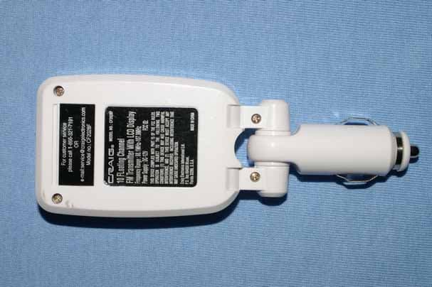
PVDCF2028F
Apr 05, 2006FM Transmitter
Equipment Class
DXX - Part 15 Low Power Communication Device Transmitter
PVDHT-U20
Jan 23, 2006Wireless Microphone
Equipment Class
TNF - Licensed Non-Broadcast Transmitter Held to Face
PVDHT-V20
Jan 22, 2006Wireless Microphone
Equipment Class
TNF - Licensed Non-Broadcast Transmitter Held to Face