PW7SDV01Staff Device
IDEO PRODUCT DEVELOPMENT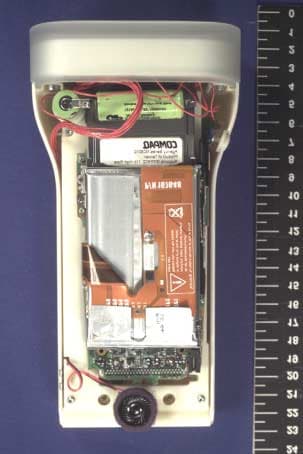
Click to zoom
Application Details
- Equipment Class
- DXX - Part 15 Low Power Communication Device Transmitter
- Date of Grant
- Dec 09, 2001
- Application Purpose
- Original Equipment
- Date of Application
- Dec 09, 2001
- Equipment Note
- Staff Device
- Frequency Range
- 13.55300000 - 13.56700000
- Company
- IDEO PRODUCT DEVELOPMENT
- Country
- United Kingdom
Documents & Files
Document Text
Text extracted from the exhibit documents filed with the FCC. Open a document above to read the original.
Users Manual
Prada Staff Device & Charging Station User Manual DRAFT 26th September 2001 staff_device_documentation_11.qxd 26/11/2001 11:21 Page 1 staff_device_documentation_11.qxd 26/11/2001 11:21 Page 2 staff device . . . . . . . . . . . . . . . . . . . . . . . . . . . . . . . . . . . . . . . . . . . . . . . . . . . . . . . . . . . . . . . . .5 external features . . . . . . . . . . . . . . . . . . . . . . . . . . . . . . . . . . . . . . . . . . . . . . . . . . . . . . . . .6 inside the case . . . . . . . . . . . . . . . . . . . . . . . . . . . . . . . . . . . . . . . . . . . . . . . . . . . . . . . . . . .8 hardware components . . . . . . . . . . . . . . . . . . . . . . . . . . . . . . . . . . . . . . . . . . . . . . . . . . . . .9 laser pointer . . . . . . . . . . . . . . . . . . . . . . . . . . . . . . . . . . . . . . . . . . . . . . . . . . . . . . . . . . . .10 software configuration . . . . . . . . . . . . . . . . . . . . . . . . . . . . . . . . . . . . . . . . . . . . . . . . . . . . .11 iPAQ standard settings . . . . . . . . . . . . . . . . . . . . . . . . . . . . . . . . . . . . . . . . . . . . . . . . . . . .12 regulatory information . . . . . . . . . . . . . . . . . . . . . . . . . . . . . . . . . . . . . . . . . . . . . . . . . . . . .13 specifications . . . . . . . . . . . . . . . . . . . . . . . . . . . . . . . . . . . . . . . . . . . . . . . . . . . . . . . . . . .14 charging station . . . . . . . . . . . . . . . . . . . . . . . . . . . . . . . . . . . . . . . . . . . . . . . . . . . . . . . . . . . .17 regulatory information . . . . . . . . . . . . . . . . . . . . . . . . . . . . . . . . . . . . . . . . . . . . . . . . . . . . .18 specifications . . . . . . . . . . . . . . . . . . . . . . . . . . . . . . . . . . . . . . . . . . . . . . . . . . . . . . . . . . .19 troubleshooting . . . . . . . . . . . . . . . . . . . . . . . . . . . . . . . . . . . . . . . . . . . . . . . . . . . . . . . . . . . . .20 Contents3 Prada Staff Device & Charging Station User Manual staff_device_documentation_11.qxd 26/11/2001 11:21 Page 3 staff_device_documentation_11.qxd 26/11/2001 11:21 Page 4 staff device This section of the documentation covers the hardware aspects of the Prada Staff Devicein the form of a standard platform for Prada’s in-store sales tool. It is intended for use initially as guidance for Prada’s software implementation partner. In the longer term, it is designed to be a source of reference for the in-store Prada IT support team. 5 staff_device_documentation_11.qxd 26/11/2001 11:21 Page 5 6external features Power switch Laser pointer button Stylus Display Reset Looking at the outside of the device, the following features are accessible: Power switch This works just like the ON/OFF button on the standard PocketPC. Press (gently) once to switch on and again to switch off. Laser pointer button To operate the laser pointer, press and hold the laser pointer button. When released, the laser beam will switch off. WARNING, before operating, ensure that the device is pointing away from yourself, and not at anybody else. See notes later about laser safety. Touch screen display The display shows the user interface. To enable the display, switch the device on using the power switch mentioned above. If the display becomes dim (the backlight has switched off), tap on the screen once to re-enable the backlight. Stylus and stylus retaining slot The stylus is stored in the slot at the base of the device. It can be removed and used for more precise interaction with the touch screen display. Reset hole The small hole at the base of the device is for resetting the device, should a serious error occur. This will re-boot the processor unit, but will not remove data or applications from the device. staff_device_documentation_11.qxd 26/11/2001 11:21 Page 6 At the front of the device, there is a translucent rubber end section. Within this section are a number of clear transmission points: Charging lamp When the device is docked in its charging unit (see later), this blue lamp flashes to indicate charging is in progress. When the lamp is constantly on, then charging is complete. If this lamp flashes during normal use, it is a warning that the batteries need to be charged. Laser beam Within the central cluster is the laser beam transmission hole. The light from the laser beam comes out of this point. Avoid looking into this hole with the laser beam activated. It is wise not to look into this hole at any time as it might be possible to accidentally press the laser beam button. Infra-red port the infra-red port is used to communicate with the device from a desktop PC. this may be needed when loading new software onto the device when first use. There is also another hole within the central cluster that is not currently used. 7 Not used Infra-red port Charging lamp Laser beam WARNING. Do not stare into beam staff_device_documentation_11.qxd 26/11/2001 11:21 Page 7 inside the case 8 Chargin g circuit Laser power switch Processor (inside) LCD screen (underside) Laser Battery pack for laser and Battery for expansion pack & network card iPAQ main battery (inside) Wireless network card Speaker staff_device_documentation_11.qxd 26/11/2001 11:21 Page 8 It is not envisaged that the staff devicewill be opened by staff, however it may be considered useful information to understand the internal components that create this product. Inside the Prada staff deviceare a number of standard electronic components, as well as some custom made elements. Processor The processor component is a Compaq iPaq (model 3630) with 32MB RAM. This is mounted inside the chassis. The main battery is mounted inside the chassis, providing power to the processor and LCD screen. LCD screen The display is mounted to the chassis inside the case. Networking The iPAQ expansion jacket provides the expansion slot and battery power for the network card. The networking is provided by a wireless network card. Laser unit The laser pointer is a 1 mW Class II laser d…
Text truncated - open the document above for the full version.
Block Diagram
5 5 4 4 3 3 2 2 1 1 DD CC BB AA CHARGER CONTACTS SD000 <RevCode> STAFF DEVICE GENERAL ASSEMBLY(ELECTRICAL) A4 11Friday, June 15, 2001 Title SizeDocument NumberRev Date:Sheet of WIRELESS LAN CHARGER +LOGIC PCB SD001 J4-1 J4-2 J2-2J2-1 J1[1..6] J3[1..8] J5[1..2] PUSHBUTTON PCB SD002 SERIAL INTERFACE PCB SD003 PWR+PWR- J2[1..12] J1[1..6] LASER DIODE MODULE (INCL CABLE ASS'Y) RFID MODULE J1[1..8] BATTERY PACK SD004 (INCL CABLE ASS'Y) RED BLACK RED BLACK CABLE ASSEMBLY = SD005 CABLE ASSEMBLY = SD007 CABLE ASSEMBLY = SD006 IPAQ RS232[1..12]PCM
External Photos
EQUIPMENT : STAFF DEVICE TEST REPORT NUMBER: CTMS 2001/1967A FCC Identifier : PW7 SDV01 CTMS FCC Registration Number: 93385 Page 1 of 5 EXTERNAL PHOTOGRAPHS OF STAFF DEVICE Page No Transmitter Front View 2 Transmitter Rear View 3 Transmitter Top View 4 Transmitter Internal View 1 5 EQUIPMENT : STAFF DEVICE TEST REPORT NUMBER: CTMS 2001/1967A FCC Identifier : PW7 SDV01 CTMS FCC Registration Number: 93385 Page 2 of 5 Transmitter Front View EQUIPMENT : STAFF DEVICE TEST REPORT NUMBER: CTMS 2001/1967A FCC Identifier : PW7 SDV01 CTMS FCC Registration Number: 93385 Page 3 of 5 Transmitter Rear View EQUIPMENT : STAFF DEVICE TEST REPORT NUMBER: CTMS 2001/1967A FCC Identifier : PW7 SDV01 CTMS FCC Registration Number: 93385 Page 4 of 5 Transmitter Top View EQUIPMENT : STAFF DEVICE TEST REPORT NUMBER: CTMS 2001/1967A FCC Identifier : PW7 SDV01 CTMS FCC Registration Number: 93385 Page 5 of 5 Transmitter Inside View 1
Internal Photos
EQUIPMENT : STAFF DEVICE TEST REPORT NUMBER: CTMS 2001/1967C FCC Identifier : PW7 SDV01 CTMS FCC Registration Number: 93385 Page 1 of 6 INTERNAL PHOTOGRAPHS OF STAFF DEVICE Page No Transmitter Internal View 1 2 Transmitter Internal View 2 3 Transmitter Internal View 3 4 Transmitter Internal View 4 5 Transmitter Internal View 5 (Antenna) 6 EQUIPMENT : STAFF DEVICE TEST REPORT NUMBER: CTMS 2001/1967C FCC Identifier : PW7 SDV01 CTMS FCC Registration Number: 93385 Page 2 of 6 Transmitter Inside View 1 EQUIPMENT : STAFF DEVICE TEST REPORT NUMBER: CTMS 2001/1967C FCC Identifier : PW7 SDV01 CTMS FCC Registration Number: 93385 Page 3 of 6 Transmitter Inside View 2 EQUIPMENT : STAFF DEVICE TEST REPORT NUMBER: CTMS 2001/1967C FCC Identifier : PW7 SDV01 CTMS FCC Registration Number: 93385 Page 4 of 6 Transmitter Inside View 3 EQUIPMENT : STAFF DEVICE TEST REPORT NUMBER: CTMS 2001/1967C FCC Identifier : PW7 SDV01 CTMS FCC Registration Number: 93385 Page 5 of 6 Transmitter Inside View 4 EQUIPMENT : STAFF DEVICE TEST REPORT NUMBER: CTMS 2001/1967C FCC Identifier : PW7 SDV01 CTMS FCC Registration Number: 93385 Page 6 of 6 Transmitter Inside View 5 (Antenna)
Operational Description
IDEO London Page 1 of 1 26 Nov 2001 Staff device (SDV01) description of operation Read with reference to system diagram “sd000system.pdf”. The staff device is an information appliance used in a commercial environment by trained staff. The device is not used by, or sold to the general public. The device includes a computer system based on a Compaq ipaq. The ipaq includes a 206MHz microprocessor, flash memory and a colour LCD display backlit by an electroluminescent source. Network services are provided by a 2.45 GHz Wireless LAN module. The module is interfaced directly to the ipaq via a PCMCIA slot system. The Wireless LAN module has FCC approval. The ipaq is connected through RS232 serial port to pcb SD001 (Charger and Logic). RS232 signals from the ipaq are converted to TTL signals which are used to communicate with the RFID module. The 13.5 MHz RFID module is used for detecting RFID tags. The SD001 pcb includes a charger circuit for charging two NiMH batteries (battery pack SD004) and provides a 5V DC power supply. A 4MHz PIC processor is used to manage state and drive indicator lamp logic. In normal operation the staff person runs software on the device and accesses a web based information system using the 2.45 GHz module. At intervals an RFID tag is scanned by the RFID module and it’s data read. This data is transmitted to the serial port of the ipaq. The data is used by software to navigate the web based information system. The RFID module is polled once per second while the software is running, when it is polled the RF electronics are energised to scan for a tag. Normal read range for tags is 1-5 cm.
Parts List/Tune Up Info
PARTS LIST FOR SD001 REV2.0 Item Quantity Reference part supplier stock number 1 2 C1,C2 0.047uF 0603 ceramic multilayer FEC 2 3 C3,C4,C5 0.33uf 35V TANT AVX TAJA334M035 3 2 C8,C6 10uf 35V TANT AVX TAJC106M035 4 2 C7,C9 0.01uf 0603 CERAMIC MULTILAYER FEC 5 1 C10 1uf 35V TANT AVX TAJA105M035 6 1 C12 100uF 16V TANT AVX TAJD107M016 7 2 C14,C13 0.1UF 0603 CERAMIC MULTILAYER FEC 8 1 D1 RB411D SOT23 663-153 FEC 663-153 9 1 D2 BAS16LT1 SOT23 FEC 934-100 10 1 D3 RB411D SOT23 11 1 D4 3MM T1/LED BLUE FEC 942-480 12 1 F1 fuse 1A63v/1206 RS 219-5885 13 1 J1 MOLEX 53398-0690 SMD STRAIGHT HEADER FEC 889-398 14 2 J5,J2 MOLEX 53398-0290 SMD STRAIGHT HEADER FEC 889-374 15 1 J3 MOLEX 52746-0890 R/A BOTTOM CONTACT 0.5MM SMD ZIF SKT FREE ISSUE 16 1 J4 PCB PAD 0.5mm dia 17 1 L1 22uH DT3316-223 coilcraft COILCRAFT 18 1 Q1 PZT2907A SOT-223 FEC 19 1 Q2 TN0201T FEC 739-121 20 1 R1 150R 5% 0603 21 1 R2 0R 0603 22 3 R3,R7,R12 10K 5% 0603 23 1 R4 68k 0603 5% 24 1 R5 22k 5% 0603 25 1 R6 0.6R 1% 26 1 R8 20k 5% 0603 27 2 R14,R9 100k 5% 0603 28 1 R10 68R 5% 0603 29 1 R11 33R 5% 0603 30 1 R13 1M 5% 0603 31 1 U1 MAX3224ECAP SSOP-20 MAXIM 32 1 U2 MAX712CSE S0IC-16 NARROW MAXIM 33 1 U3 MAX756CSA 150MIL SOIC-8 MAXIM 34 1 U4 PIC12C508A-04/SN 150MIL SOIC-8 FREE ISSUE -------------------------------------------------------------------------------------------- PARTS LIST FOR BOARD SD002 Revision: 1 Bill Of Materials June 15,2001 21:33:13 Page1 Item Quantity Reference Part 1 2 J1,J2 CON1 2 1 SW1 VERTICAL PCB, RS320-900 ------------------------------------------------------------------------------------------ PARTS LIST FOR BOARD SD003 Revision: 0 Bill Of Materials June 15,2001 21:29:43 Page1 Item Quantity Reference Part 1 1 J1 MOLEX 53398-0690 SMD STRAIGHT HEADER 2 1 J2 FOXCONN QV-50123-C01 3 2 J4,J3 CON1 ------------------------------------------------------------------------------------------
Schematics
5 5 4 4 3 3 2 2 1 1 DD CC BB AA GND TTL-RXD GND TTL-TXD PWR-ON n/c n/c SCAN MODULE 5VDC AC ADAPTOR INPUT LASER DIODE MODULE R3=[(Vin/Vref)-1]R4 PUSH BUTTON SWITCH LBO: Vin<=1.5v PAD DIA. 0.5MM (TO SUIT 28AWG WIRE 7 X 0.13) PAD DIA. 0.5MM (TO SUIT 28AWG WIRE 7 X 0.13) PCB TERMINAL (REFER TO MECH. DWG) CTS ADAPTOR V IN RTS IPAQ SERIAL CONNECTOR RXD ADAPTOR V IN UDC-P TXD PCB TERMINAL (REFER TO MECH. DWG) - + USB DTR UDC-N GND GND DCD SD0002 Staff Device RFID Interface & Power supply A2 11Monday, October 29, 2001 Title SizeDocument NumberRev Date:Sheet of AC-IN 5v 5v 5V 5V 5v 5v +C4 0.33uf 35V TANT Q2 TN0201T +C3 0.33UF 35V TANT J3 MOLEX 52746-0890 R/A BOTTOM CONTACT 0.5MM ZIF SKT 1 2 3 4 5 6 7 8 J1 MOLEX 53398-0690 SMD STRAIGHT HEADER 1 2 3 4 5 6 + C5 0.33uf 35V TANT +C2 0.047uF R13 1M +C1 0.047uF U1 MAX3224ECAP SSOP-20 1 2 4 5 6 11 18 3 7 19 17 8 15 10 13 12 16 9 14 20 RDY C1+ C1- C2+ C2- INVALID GND V+ V- VCC T1OUT T2OUT R1OUT R2OUT T1IN T2IN R1IN R2IN FORCEON FORCEOFF Q1 PZT2907A SOT-223 1 2 3 +C10 1uf 35V TANT J2 MOLEX 53398-0290 SMD STRAIGHT HEADER 1 2 C9 0.01uf D1 RB411D SOT23 663-153 F1 fuse 1A63v/1206 RS219-5885 R2 0R U2 MAX712CSE S0IC-16 NARROW 13 14 8 11 15 16 1 5 6 7 3 4 9 10 2 12 GND DRV FASTCHG CC V+ REF VLIMIT THI TLO TEMP PGM0 PGM1 PGM2 PGM3 BATT+ BATT- R6 0.6R 1% R3 10K R1 150RC7 0.01uf R5 22k D2 BAS16LT1 SOT23 934-100 R4 68k +C6 10uf 35V TANT +C8 10uf 35V TANT R8 20k R9 100k R10 68R C13 0.1UF R7 10K D3 RB411D SOT23 J4PCB PAD 0.5mm dia 1 2 +C12 100uF 16V TANT U3 MAX756CSA 150MIL SOIC-8 5 7 6 4 8 3 2 1 LBI GND OUT LBO LX REF 3/5 SHDN J5MOLEX 53398-0290 SMD STRAIGHT HEADER 1 2 L1 22uH DT3316-223 coilcraft R14 100K R11 33R R12 10K U4 PIC12C508A-04/SN 150MIL SOIC-8 1 2 34 5 6 7 8 VDD GP5/OSC1/CLKIN GP4/OSC2GP3/MCLR/VPP GP2/TOCKI GP1 GP0 GND D4 3MM T1/LED BLUE FEC942-480 C14 0.1uF BT2 PANASONIC HHR120AA J1 MOLEX 51021-0200 FEMALE HOUSING, 50058 CRIMP 1 2 BT1 PANASONIC HHR120AA J2 CON1 1 J1 CON1 1 SW1 VERTICAL PCB, RS320-900 J4 1 J2 FOXCONN QV-50123-C01 1 2 3 4 5 6 7 8 9 10 11 12 J3 1 J1 MOLEX 53398-0690 SMD STRAIGHT HEADER 1 2 3 4 5 6 V-ADP RS232-TXD PWR-ON RS232-RXDTTL-TXD TTL-RXD RS232-RXD RS232-TXD TTL-TXD PWR-ON TTL-RXD FASTCHG V-BATV-ADP AC-IN V-BAT LOW-BAT 5v FASTCHG AC-IN LOW-BAT
Test Report
EQUIPMENT : STAFF DEVICE TEST REPORT NUMBER: CTMS 2001/1967 FCC Identifier : PW7 SDV01 CTMS FCC Registration Number: 93385 Page 1 of 29 TEST REPORT ON STAFF DEVICE Hand-held PC device with a transmitter operating on 13.560 MHz FCC Procedures Part 15 TEST REPORT NUMBER CTMS 2001/1967 August 2001 Prepared for: IDEO Europe LTD. White Bear Yard, 144a Clerkenwell Road, London, EC1R 5DF United Kingdom. This results in this report refer to the tested unit only EQUIPMENT : STAFF DEVICE TEST REPORT NUMBER: CTMS 2001/1967 FCC Identifier : PW7 SDV01 CTMS FCC Registration Number: 93385 Page 2 of 29 CAMBRIDGE TEST & MEASUREMENT SERVICES Certificate of Application Cambridge Test and Measurement Services Ltd., certifies that the product tested was fully compliant with the requirements of Parts 15 of the FCC Code of Regulations 47CFR, the results of which are contained in this test report No: CTMS 2001/1967. I certify that the application was prepared under my supervision and that to the best of my knowledge and belief, the facts set forth in this application and technical data, are true and correct. Signature : Date : Name : David Fisher Title : Radio Technical Manager EQUIPMENT : STAFF DEVICE TEST REPORT NUMBER: CTMS 2001/1967 FCC Identifier : PW7 SDV01 CTMS FCC Registration Number: 93385 Page 3 of 29 General Test Information Date Test Sample Received : 19/07/2001 Date Testing Started : 01/08/2001 Date Testing Finished : 03/08/2001 Equipment Serial Number : N.A. (Test sample) CTMS Project Number : 2000/1967 Test Engineer : M. Billis Report Copy No 1 EQUIPMENT : STAFF DEVICE TEST REPORT NUMBER: CTMS 2001/1967 FCC Identifier : PW7 SDV01 CTMS FCC Registration Number: 93385 Page 4 of 29 Contents list and Information 2.1033 Application for Certification For use in accordance with FCC Rules and Regulations 47 CFR parts 2 and parts 15. 2.1033 (b) (1) Name of applicant : Ideo Europe Ltd. Address of applicant : White Bear Yard, 144a Clerkenwell Road, London, EC1R 5DF, United Kingdom. Contact: Mr. S. O’Connor, 2.1033 (b) (2) FCC Identifier : PW7 SDV01 Model Type Number : Staff Device 2.1033 (b) (3) Installation and operating instructions : User Guide, see exhibit 2.1033 (b) (4) Brief description of circuit function : see exhibit 2.1033 (b) (5) Block diagram showing frequency 2.1034 of oscillators : see exhibit 2.1035 2.1033 (b) (6) Report of measurements : 2.1033 (7) Photographs of equipment and identification plate / label : Page 12 15 Subpart A General 15.31 Measurement standards (OATS) : Page 5 15.33 Frequency range of radiated measurements : Page 6 15.35 Measurement detector and bandwidths : Page 6 15 Subpart C Intentional Radiators 15.225(a) Radiated emission limits (fundamental) Page 7 15.209(a) Radiated emission limits (spurious) : Page 10 15.225(c) Frequency tolerance of fundamental General Information and Attachments : Company Accreditations & Credentials : Page 22 EQUIPMENT : STAFF DEVICE TEST REPORT NUMBER: CTMS 2001/1967 FCC Identifier : PW7 SDV01 CTMS FCC Registration Number: 93385 Page 5 of 29 15.31 Measurement standards The measurement facilities at Cambridge Test and Measurement Services LTD, are in accordance with ANCI C63.4 and lodged with the FCC under rule 2.948, a letter from the FCC recognising compliance with the requirements was dated March 02,1999 with the registration number 93385. Open Area Test Site (OATS) Transmission Axis 3 m / 20 m EUT d where d is the maximum EUT dimension 2D 3m / 20m 40m 10m Automatic LISN LISN √ 3.D 1 - 4 m Automas t ESVS10 Receiver Fibre Optic Control PC Controller EUT Equipment Test Set Up Antenna to EUT Distance EUT Mains Supply: Fed under the ground plane EQUIPMENT : STAFF DEVICE TEST REPORT NUMBER: CTMS 2001/1967 FCC Identifier : PW7 SDV01 CTMS FCC Registration Number: 93385 Page 6 of 29 Frequency spectrum to be investigated - 47 CFR 15.33 The range of frequency search was from 9 kHz 1GHz. Measurement detector and bandwidths 47 CFR 15.35 Measurements below 1000 MHz are taken using a quasi-peak detector which has been calibrated to the requirements of CISPR 16-1. General Test Conditions Laboratory environment . Ambient Temperature : 21 °C Relative Humidity : 50 % Open Area test Site : 23 °C Test Instruments used Receiver: Rohde & Schwarz type ESHS 10 Receiver: Rohde & Schwarz type ESVS 10 Antenna: Schaffner Chase bi-log type CBL6141A Antenna: Emco active loop type 6502 EQUIPMENT : STAFF DEVICE TEST REPORT NUMBER: CTMS 2001/1967 FCC Identifier : PW7 SDV01 CTMS FCC Registration Number: 93385 Page 7 of 29 Transmitter emission limits- 47 CFR 15.225 and 15.209 The Transmitter (the EUT) was fitted with a new battery, set to continuous transmit and was placed on a wooden table at a distance of 3m or 20m from the receiving antenna, as appropriate. The radiated field strength for each spurious emission was detected and measured on a calibrated receiver. The antenna was orientated in the horizontal and vertical planes and was raised and lowered between a height of 1 and 4 metres so as to ensure the maximum level of any spurious emission was detected. The EUT was rotated through 360° at each orthogonal axis, the emission levels for each spurious were observed on the receiver and recorded. For each of the emissions detected the EUT was switched off to determine the emission was that of the EUT. For measurement of emissions below 30 MHz a Calibrated shielded loop antenna was used. EQUIPMENT : STAFF DEVICE TEST REPORT NUMBER: CTMS 2001/1967 FCC Identifier : PW7 SDV01 CTMS FCC Registration Number: 93385 Page 8 of 29 Results in accordance with Part 15.225 Emission Limits Field Strength of Fundamental Operating Frequency (MHz) Emission Frequency (MHz) Identity Result μV/m @ 30m Spec limit at this frequency μV/m @ 30m 13.560 13.560 fundamental (fc) 10.33 10,000 This measurement was carried out at 20m, and the result converted to a 30m equivalent, as the field generated by the EUT was below the noise floor of the measurement equipment at 30m. The conversion was done using fre…
Text truncated - open the document above for the full version.
Test Setup Photos
EQUIPMENT : STAFF DEVICE TEST REPORT NUMBER: CTMS 2001/1967B FCC Identifier : PW7 SDV01 CTMS FCC Registration Number: 93385 Page 1 of 2 TEST SET-UP PHOTOGRAPHS OF STAFF DEVICE Page No Transmitter Test Set-Up 2 EQUIPMENT : STAFF DEVICE TEST REPORT NUMBER: CTMS 2001/1967B FCC Identifier : PW7 SDV01 CTMS FCC Registration Number: 93385 Page 2 of 2 Test Set-up
Contact Information
Applicant
Stephen O'Connor(Manager)
[email protected]+44 207 713 2649
Technical Contact
Ideo Europe LtdSteve O'Connor
[email protected]+44 207 713 2649
White Bear Yard · London · United Kingdom
Non-Technical Contact
Ideo Europe LtdSteve O'Connor
[email protected]+44 207 713 2600
Test Firm
Cambridge Test & Measurement ServicesJon Larkin
Technical Specifications
| # | Rule Parts | Frequency Range | Power Output | Tolerance |
|---|---|---|---|---|
| 1 | 15C | 13.553 MHz - 13.567 MHz | 10.30 µW | 0.0020000000 % |