PWL326060 GHz High Capacity Data Transceiver
Unique Broadband Systems, Inc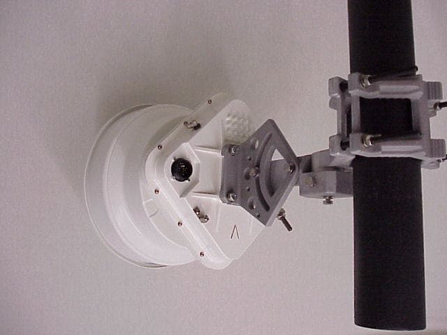
Click to zoom
Application Details
- Equipment Class
- DXX - Part 15 Low Power Communication Device Transmitter
- Date of Grant
- Mar 10, 2002
- Application Purpose
- Original Equipment
- Date of Application
- Nov 08, 2001
- Equipment Note
- 60 GHz High Capacity Data Transceiver
- Frequency Range
- 60250.00000000 - 62750.00000000
- Country
- United States
Documents & Files
Document Text
Text extracted from the exhibit documents filed with the FCC. Open a document above to read the original.
Users Manual
3260-9901 Rev.1.0 Fiber Connection™ Radio 60 GHz Sonet OC-3 or OC-12 Product Manual This device complies with Part 15 of the FCC Rules (1). This device may not cause harmful interference and (2). This device must accept any interference received including interference that may cause undesired operation. FCC ID # 0433260 Fiber Connection Series Microwave Radio Operator’s Manual, Rev. 1ii About this manual This document describes the architecture, installation, operation and commissioning of the Fiber Connection™ 60 GHz Microwave Radio. Organization – Table of Contents Proprietary Notice Document History Product Safety Guide Warranty & Service Information Section 1.0 – System Description and Overview Section 1.1 – System Applications Section 1.2 – System Features Section 1.3 – Equipment Layout and Main Assemblies Section 1.4 – Outdoor Unit Signal Flow Section 1.5 – System Interfaces Section 2.0 – Technical Specifications Section 2.1 – Overview Section 2.2 – Configuration Section 2.3 – Requirements Section 2.4 – RF Performance Requirements Section 2.5 – Power Requirements Section 2.6 – Environmental Requirements Section 2.7 – Mechanical Requirements Section 2.8 – Optional Indoor Unit (IDU) Section 2.9 – Reliability Section 3.0 – Radio Outdoor Unit (ODU), Operation & Commissioning Section 3.1 – Unpacking and Handling the Radio System Section 3.2 – Mechanical Inspection, Inventory and Matching the Radios Section 3.3 – Radio ODU Installation Prerequisites Section 3.4 – Radio ODU Installation Procedures Fiber Connection Series Microwave Radio Operator’s Manual, Rev. 1iii Section 3.5 – Align the Radio ODU with Integrated Antenna Section 3.6 – Removing the Radio ODU from the Mount Assembly Section 3.7 – Optional Indoor Unit Installation Section 3.8 – Radio Link (ODU and Indoor Unit) Commissioning Section 4.0 – Using the Wireless Remote to Configure and Monitor Radio Section 5.0 – Using the “FiberConn Monitrol” Software Craft Interface Tool (CIT) Section 5.1 – About this Section Section 5.2 – Functionality Section 5.3 – Installing “FiberConn Monitrol” Software Section 5.4 – Using the “FiberConn Monitrol” Software Section 5.5 – Procedure When Using “FiberConn Monitrol” Section 6.0 – SNMP MIB Installation Procedure Section 6.1 – About this Section Section 6.2 – Configure the Optional Indoor Unit SNMP Agent Section 6.3 – Add and Compile the “Sierra FiberConn MIB” Appendix A – North American Standards Appendix B - Glossary Fiber Connection Series Microwave Radio Operator’s Manual, Rev. 1iv Proprietary Notice No part of this publication may be copied, distributed, transmitted, stored in a retrieval system or translated into any human or computer language without prior written permission of SierraCom. SierraCom has made every effort to ensure that the instructions contained in this document are adequate and free of errors and omissions. SierraCom will, if necessary, explain issues, which may not be covered by this document. SierraCom liability for any errors in this document is limited to the correction of errors and the aforementioned advisory services. This document has been prepared for professional and properly trained personnel and the customer assumes all responsibility when using this document. SierraCom welcomes customer comments as part of the process of continual development and improvement of the documentation in the best way possible from the user’s viewpoint. Please submit your comments to your SierraCom sales representative at the following address: To allow for the introduction of design improvements, specifications are subject to change without notice. ©2001 SierraCom Fiber Connection Series Microwave Radio Operator’s Manual, Rev. 1v Document History Release Number Reason for ChangeRelease DateAuthorization Signature 1.0First Time ReleaseAug 01, 2001 Fiber Connection Series Microwave Radio Operator’s Manual, Rev. 1vi Safety points you should know about this product. ++Read all of these instructions ++Adhere to all notes, warnings, cautions and instructions within this document. 1. Read Instructions All safety, note, warning and caution statements should be read before operating product. 2. Retain Instructions The safety and installation instructions should be retained for future reference. 3. Heed Warnings All notes, warning and caution statements in this document should be adhered to. 4. Follow Instructions All notes, cautions and warnings should be followed. 5. ESD Warning The radio terminal contains ESD (Electrostatic Discharge) sensitive devices. Avoid direct contact with interface connector pins. 6. Cleaning Do not use liquid cleaners or aerosol cleaners. Use a damp cloth for cleaning. 7. Attachments Do not use attachments which are not listed within this document or which are not recommended by SierraCom. 8. Water and Moisture The Radio Terminal is designed to withstand moisture conditions typically encountered when installed outdoors. It is not designed for operation under water or to withstand water or moisture beyond the limits noted in the product specifications. Product Safety Fiber Connection Series Microwave Radio Operator’s Manual, Rev. 1vii 9. Mounting Equipment and Accessories Do not place this product on an unstable cart, stand, tripod, bracket or table. The product could fall, causing serious injury to personnel, and serious damage to the product. Any mounting of the radio should follow the manufacturer’s instructions, and should use a mounting accessory recommended by SierraCom. 10. Power Sources This product should be operated only from the type of power source indicated in this document. 11. Damage Requiring Service Unplug the product from its power source and refer to service personnel under the following conditions: a. When the power supply cord or plug is damaged. b. If liquid has been spilled or objects have fallen into the product. c. If the product does not operate normally, adjust only those controls that are covered by this document. Improper adjustment of an…
Text truncated - open the document above for the full version.
Cover Letter(s)
September 25, 2001 Attention: Intertek Testing Services NA, Inc. Application Examiner Reviewing Engineer Re: Request for confidentiality per Section 0.459 of FCC Rules Applicant: SierraCom FCC ID: PWL3260 To whom it may concern: Request is hereby submitted by SierraCom, a Division of Sierra Networks, Inc., to withhold from public review certain portions of the application for equipment certification for the referenced FCC identifiers. In particular, the following sections of the application and report are requested to be kept confidential: • Schematics • Parts Lists • Assembly Drawings • Detailed Block Diagram Rationale for request for confidentiality: SierraCom has invested considerable time and materials in research and development to produce the referenced product. Disclosure of the confidential portions of this application to competitors would not only give them competitive advantage in developing similar products, but would also disclose new technologies developed in the area of millimeter wave high capacity data transceivers. The $135 fee for confidentiality has been submitted along with the fee for certification. If you have questions or need further information, please contact the undersigned. Sincerely, Richard J. Hughes V.P. Engineering, SierraCom (508) 435-2400 [email protected]
Cover Letter(s)
November 13, 2001 To Whom It May Concern: I have uploaded an attachment that should have a different Exhibit Type and should say “Confidential”, which was not done on my part. I have uploaded an exhibit called TX x2 Multiplier under RF Exposure Info and Confidiential was NOT checked off, which is all incorrect. Please correct to the following format: Exhibit Type: Schematics Description of Exhibit: TX x2 Multiplier Confidential MUST be checked off Display Mode: PDF If you have any further questions regarding this issue, please feel free to contact me via e-mail at [email protected] or call me direct at 978-635-8653. Thank you, Da nie lle Grave lle TCB Administrator Boxborough, MA 01719
External Photos
3261-0000, 3264-0000 Top Level with antenna, mounting bracket, mounted on pole 3261-0000, 3264-0000 Top Level with antenna, mounting bracket, mounted on pole. Back view 3261-0000, 3264-0000 Top Level with antenna mounting bracket, mounted on pole. Back view, Right 3261-0000, 3264-0000 Top Level with antenna mounting bracket, mounted on pole. Back view, left Fiber, Data and DC connection AGC Antenna alignment port
Internal Photos
3261-0030 SONET Interface Board Top 3261-0030 SONET Interface Board Bottom 3261-0020 Processor Board Top 3261-0020 Processor Booed Bottom 3261-0040, 3264-0040, RF deck with cover, top 3261-0040, 3264-0040, RF deck without Diplexor, LNA and SSPA 3261-0040, 3264-0040 without cover 3261-0010, 3264-0010, RF board back ODU Housing without RF Deck ODU Housing without RF Deck and Processor Board ODU Housing without RF Deck and Processor Board and SONET Interface board ODU Housing Back Fiber Data and DC connection Ground lug
Operational Description
OPERATION DESCRIPTION: The Fiber Connection Series Radio operate in the 60GHz (57 to 64 GHz) unlicensed band. The Fiber Connection Radio Product is designed to carry Synchronous based (SONET: OC-3 or OC-12) data traffic. The radio uses Binary Phase Shift Keying (BPSK) modulation scheme to carry traffic of 155 Mb/s or 622 Mb/sec. The Fiber Connection Radio is designed to support a variety of short-range applications (distances up to 1 km) and to operate in environments where frequency congestion is problematic. The signal absorption by oxygen gas (O 2 ) and the use of the narrow beam-width antennas allow for frequency re-use factor of one, thereby eliminating the need for costly frequency coordination. v System Application: Fiber Connection as Hot Standby Radio for Free- Space Optical Radios The Fiber Connection Radios in conjunction with the Free-Space Optical Radios provide a robust point-to-point communication link that is relatively immune to environmental conditions. The dust and fog that adversely affect the Free-Space Optical Radios do not appreciably hinder communication using the 60 GHz radio product. On the other hand, the rain and snow that affect 60 GHz radio do not cause appreciable degradation of the Free-Space Optical communications. Fiber Connection Radio as a Fiber Cable Bridge Across Obstacle The Fiber Connection radio is designed to interface to a Fiber Terminal that carry OC-3/OC-12 traffic. In applications here obstacles such as highways, rivers, parking lots or Municipal by law etc prevent extension of the Fiber cable the Fiber Connection Radio provides means to overcome this. Fiber Connection Radio Eliminates the Building Rise Congestion Building risers were originally designed to carry AC power, coax and telephone cables. In general, these risers are congested already and as such adding new cables results in major construction costs. These costs can be avoided by using the Fiber Connection Radio installed on the side of the walls of the building. Micro/Pico Cell Base Station Interconnection As the traffic density on cellular networks increases, more and more Base Stations are generally added to accommodate this need. The added Base Stations need to be interconnected by wireless backhaul equipment. Traditionally, this backhaul equipment operates in the licensed bands (13 to 38 GHz) that require frequency coordination and licensing. The Fiber Connection product eliminates frequency coordination and licensing problems. Campus High Speed Data Connections Businesses with High speed LAN data (100 Mb or 1 GigaBit Ethernet) networks that need to be connected to other buildings are limited to connections that LECs can provide. Generally, these access connections are limited to several T1s and in some cases to OC-3 capacity if a dark fiber already exists or a new one can be built. The Fiber Connection Radio can provide the capacity and connectivity as an alternative or compliment to the existing LEC connections. System Features The Fiber Connection Radio provides: ♦ Low Installation Cost (Single Outdoor Unit) ♦ Reliable Operation (Uses Robust Forward Error Correction FEC) ♦ Variety of Traffic Interface (Copper, Single, or Multi-mode Fiber Cable) ♦ Data Rates and Protocols OC-3 OC-12 ♦ Management and Configuration SNMP Version 1 ♦ Atmospheric Attenuation at 60 GHz SierraCom’s FiberConnection TM Series 60 GHz Radio for US Markets Model: 3261-0000 & 3264-0000 ISO-9001 Certified Facility ISO-9001 Certified Facility A Division of Sierra Networks, Inc. 99 South Street, Hopkinton, MA 01748 Tel 508 435-2400 ext 264 Fax 508 435-2022 Email [email protected]://www.sierracom.com Specifications subject to change. Specifications System Frequency Range(57.0) 59.0 to 64.0 GHz Applicable StandardFCC Part 15, Subpart C, 15.255 T/R Spacing2500 MHz Frequency Variation30 MHz total (Temperature & Aging) System Gain77 dB Modulation FormatDBPSK Transmitter RF Output Power+10 dBm Typical Spurious EmissionsFCC Part 15.255 Receiver Threshold–57 dBm at 10-6 BER @ OC-12 –63 dBm at 10-6 BER @ OC-3 Maximum Input–20 dBm Noise Figure12 dB Typical Antenna and Mount DescriptionParabolic Dish Gain41 dBi Typical PolarizationVertical or Horizontal 1 Size14” Dia x 9” Long Coarse Adjust Range±90° Azimuth ±90° Elevation Fine Adjust (One Turn)2.0° Azimuth 1.0° Elevation Environmental Operating Temperature–35 °C to +55 °C Wind110 km/h Operating 200 km/h Survival Power Supply ODU Supply Voltage±48 VDC 2 Power Consumption35W Maximum ProtectionRe-settable Fuse Physical Dimensions11.05” x 11.05”” x 3.25” (see Note 3) φ14” x 27” including Antenna and Mount Weight5 kg Network Management Management ProtocolSNMP v.1 through IDU Address AssignmentFixed or DHCP AlarmsRadio Configuration TemperatureCapacity Selection Radio FailureFEC On/Off Loss of Data (TX, RX)Loopback (Near End, Far End) TX Mute Status MonitorNetwork Functions TemperatureIP Address Configuration Power SupplyField Software Upgrade Received Signal LevelAccess Control BER PerformanceCommon Language Facility ID Also Protocol Specific Functions Indoor Interface (IDU)Optional Description1U Rackmount Patch Panel Fiber ConnectorsSC standard ST no-cost option Power SupplyBuilt-in, optional 115 VAC input, 50 W SNMPInternet LAN connection 10 Base-T. Standard RJ45 connection Traffic Interface Radio Capacity155/622 Mbps + FEC Overhead ProtocolsOC-3 SONET OC-12 SONET SONET InterfaceSMF 1310 nm Cable Outdoor ConnectorProprietary Weathertight Maximum Length1000 ft (Fiber traffic) 300 ft (Twisted Pair) Spare Fibers2 Indoor TerminationAll wires and fibers terminated FiberSC standard, ST optional Power wiresMolex 5557 Signal wiresRJ-45 Notes 1Vertical Polarization preferred 2Or 115 VAC using Optional IDU Power Supply 3Dimension excludes Antenna & Mount Preliminary
RF Exposure Info
99 South Street, Hopkinton, MA 01748* Tel: 508.435.2400, Fax: 508.435.2022 e-mail: [email protected] http://www.sierracom.com October 29, 2001 SIERRACOM’S FIBERCONNECTION SERIES 60 GHZ RADIOS, MODEL: 3261-0000-1/2 AND 3264-0000-1/2 Evaluation of Compliance with FCC Guidelines for Human Exposure to Radio Frequency Electromagnetic Fields This analysis is based on OET Bulletin 65, Edition 97-01 and performed for the SierraCom’s FiberConnection Series 60 GHz Radio Model: 3261-0000-1/2 and 3264-0000-1/2, hereafter referred as “the SierraCom’s Radio”. These radios are operating with the folowing parameters: FCC ID Number:PWL3260 Model Number3261-0000-13261-0000-23264-0000-13264-0000-2 Transmitting Frequency:60.25 GHz62.75 GHz60.25 GHz62.75 GHz Frequency Accuracy:30 MHz30 MHz30 MHz30 MHz Receiving Frequency:62.75 GHz60.25 GHz62.75 GHz60.25 GHz Protocol:OC-3OC-3OC-12OC-12 Data Rate (no FEC):155 mbs155 mbs622 mbs622 mbs Data Rate (with FEC):165 mbs165 mbs661 mbs661mbs Transmitter Output Power:6.3mW/8 dBm (typ), 10mW/10 dBm (max) T/R Spacing:2500 MHz Modulation:DBPSK Spurious Emissin:FCC Part 15, Subpart C, 15.255 Antenna Type:Parabolic Antenna Aperture:700 cm 2 Antenna Aperature Efficiency: ηη(59GHz) = 0.368, ηη(64GHz) = 0.313 Antenna Gain:41.0 dBi (max), G N = 12,589.3 Near Field Extent:439.4 cm @ 59 GHz, 476.6 cm @64 GHz Beginning of Far Field: 10.55 m @ 59 GHz, 11.44 m @ 64 GHz Avgerage ValueMaximum Value Antenna Beamwidth:1.5 deg1.1 deg Antenna Injection Power:5.0 mW (7 dBm) 10.0 mW (10 dBm) Compliance Evaluation with the FCC Guidelines for Human Exposure to Radio-Frequency Electromagnetic Fields 99 South Street, Hopkinton, MA 01748* Tel: 508.435.2400, Fax: 508.435.2022 e-mail: [email protected] http://www.sierracom.com Page 2 of 6 A. Evaluation of the worst case, maximum power density of the radiated RF power in the frequency range 59-64 GHz.: The antenna used on the SierraCom’s Radio has a parabolic surface and circular cross section. The RF power is fed to the antenna from the rectangular waveguide (WR-15) feed it her Focal Point. Radiation from this source provide a collimated beam with a circular spread angle α, where 1.1 deg < α < 1.5 deg. Because of the highly directional nature of this antenna, the likelihood of significant human exposure to RF radiation is considerably reduced. Factors that are taken into account are mainly the main-beam orientation and antenna heights above ground. To evaluate compliance with guidelines for human exposure for the systems, which are using a parabolic aperture antenna with circular cross section, the following procedure will be used: 1. Calculate Power Density on the antenna feed (waveguide horn), based on the maximum power transmitted by the waveguide (1),(3) , 2. Calculate Power Density on the antenna surface, based on maximum power level fed to the antenna (2),(3) , 3. Evaluate Power density in the near-field region (2),(3) , 4. Evaluate Power density in the transition region (2),(3) , and 5. Estimate worst case Power Density in the far-field region (1-3) , All calculations are based on the maximum power level (P 0 ), fed to the antenna. Calculations are based on the recommended method by OET Bulletin 65 (2) . 1. Antenna Feed: Based on equation [11] from the OTE Bulletin 65, the maximum power density directly in the front of the waveguide horn of the antenna is: Where: S horn = maximum power density at the antenna surface (mW/cm 2 ) P 0 = 10 mW, power fed to the antenna A w = 0.0726 cm 2 , physical area of the waveguide horn The calculated power density at the waveguide horn is S horn = 367.8 mW/cm 2 2. Antenna Surface: Based on equation [11] from the OTE Bulletin 65, the maximum power density directly in the front of the antenna (Antenna Interface) is: S surface = 4P 0 /A S horn = 4P 0 /A w Compliance Evaluation with the FCC Guidelines for Human Exposure to Radio-Frequency Electromagnetic Fields 99 South Street, Hopkinton, MA 01748* Tel: 508.435.2400, Fax: 508.435.2022 e-mail: [email protected] http://www.sierracom.com Page 3 of 6 Where: S surface = maximum power density at the antenna surface (mW/cm 2 ) P 0 = 10 mW, power fed to the antenna A = 700.0 cm 2 , effective physical area of the antenna The calculated power density at the antenna surface is S surface = 0.038 mW/cm 2 3. Near-Field Region: The extent of the near field can be described by the equation [12] from the OTE Bulletin 65: Where: R nf = extent of near-field (cm) D = 30.48 cm, diameter of the antenna λ f = λ 64 = 0.467 cm, wavelength at at RF frequency f = 64 GHz λ f = λ 59 = 0.507 cm, wavelength at worst case at RF frequency f = 59 GHz The calculated extent of near field is R nf = 439.4 cm. The maximum value of the near-field power density located on the main beam axis is calculated from equation [13]: Where: S nf = maximum near-field power density (mW/cm 2 ) η 59 = (Gλ 2 /4π)/(πD 2 /4) = 0.368 worst case scenario for the antenna operating at 59 GHz P 0 = 10 mW, RF power fed to the antenna D = 30.0 cm, effective antenna diameter The calculated maximum power density in near field is S nf = 0.014 mW/cm 2 . 4. Transition Region: The distance between near-field and far-field region is described as a transition region. The maximum extent of the transition region is to the beginning of the far-field region and is defined by R ff . R ff is described by the equation [16] from the OTE Bulletin 65: R nf = D 2 /4λλ f S nf = 16ηηP/ππD 2 R ff = 0.6D 2 /λλ f Compliance Evaluation with the FCC Guidelines for Human Exposure to Radio-Frequency Electromagnetic Fields 99 South Street, Hopkinton, MA 01748* Tel: 508.435.2400, Fax: 508.435.2022 e-mail: [email protected] http://www.sierracom.com Page 4 of 6 Where: R ff = distance to beginning of far-field (cm) D = 30.0 cm, effective diameter of the antenna λ f = λ 64 = 0.467 cm, wavelength at RF frequency f = 64 GHz λ f = λ 59 = 0.507 cm, wavelength at worst case at RF frequency f = 59 GHz The calculated beginning of the far-field region i…
Text truncated - open the document above for the full version.
Test Report
FCC Part 15 Subpart C, Section 15.255 Test Report for SierraCom on the Fiber Connection 60GHz Microwave Radio Model No.: 3260-0000 Serial No.: 11-3264-0000-2 & 12-3264-0000-1 FCC ID: PWL3260 Date of Report: November 9, 2001 Project #: 3004764 Dates of Test: September 4, 5, 6, 17-21, 2001 October 3, 4, 19, 2001 Lab Code 100270-0 Signature:___________________________Date:___________ Kouma Sinn, Test Engineer Signature:___________________________Date:___________ Michael Murphy, Staff Engineer This report shall not be reproduced except in full, without written approval of Intertek Testing Services. This report must not be used to claim product endorsement by NVLAP or any agency of the U.S. Government. The results contained in this report were derived from measurements performed on the identified test samples. Any implied performance of other samples on this report is dependent on the representative of the samples tested. Intertek Testing Services 70 Codman Hill Road, Boxborough, MA, 01719 Report # 3004764FCC Part 15.255 Certification ii Table of Contents FCC Part 15 Subpart C, Section 15.255 Test Report ...............................................................................1 1.0Summary of Tests...........................................................................................................................3 2.0General Description........................................................................................................................5 2.1Product Description................................................................................................. 5 2.2Test Methodology.................................................................................................... 6 2.3Test Facility............................................................................................................. 6 3.0System Test Configuration ............................................................................................................7 3.1Support Equipment, Cables, and Antenna List ....................................................... 7 3.2Block Diagram of Test Setup .................................................................................. 8 3.3Justification ............................................................................................................. 9 3.4Software Exercise Program ..................................................................................... 9 3.5Mode of operation during test ................................................................................. 9 3.6Modifications required for Compliance .................................................................. 9 Measurement Results ................................................................................................................................10 4.1Radiation Exposure (1.1310)................................................................................. 10 4.2Antenna Requirement (15.203) ............................................................................. 10 4.3AC Line Conducted Emission (15.207) ................................................................ 11 4.4Peak Power Density (15.255(b)(1))....................................................................... 16 4.5Average Power Density (15.255(b)(1)) ................................................................. 17 4.6Spurious emissions outside 59 – 64GHz band (15.255(c)(1)) .............................. 17 4.7Radiated emissions from digital module below 40GHz (15.255(c)(2)) ................ 18 4.8Radiated emissions between 40GHz and 200GHz (15.255(c)(3)) ........................ 21 4.9Emissions inside 59.0 – 59.05GHz band (15.255(d)) ........................................... 24 4.106 dB Bandwidth (15.255(e)(1)) ............................................................................. 24 4.11Peak output power (15.255 (e)(2)) ........................................................................ 25 4.12Frequency Stability (15.255(f)) ............................................................................. 26 List of Test Equipment..............................................................................................................................27 Appendix A – Microwave power density measurement for transmitters with high-gain antenna.....28 Appendix B – Evaluation of compliance with FCC guidelines for human exposure...........................29 Appendix C – Spectrum analyzer plots ...................................................................................................30 Intertek Testing Services 70 Codman Hill Road, Boxborough, MA, 01719 Report # 3004764FCC Part 15.255 Certification 3 1.0Summary of Tests This report is designed to show compliance with FCC Part 15 Subpart C, Section 15.255. The test procedures described in American National Standards Institute C63.4:1992 at frequencies below 40GHz and Section 15.255 (40 – 200GHz) were employed. A description of the product and operating configurations, the various provisions of the rules, the methods for determining compliance and a detailed summary of the results are included within this test report. Measurements were made to determine compliance with FCC Part 15.255 as follows: - 1.1310 to verify compliance with radiation exposure limits - 15.255(b) to determine peak power density - 15.255(c) to determine power density above 40GHz compared with a limit of 90pW/cm 2 - 15.255(d) to verify that only spurious signals are present in the 59 – 59.05GHz band - 15.255(e) to determine maximum power transmitted in the range of 59-64GHz. The limit is based on the 6dB bandwidth of the intentional signal - 15.255(f) to verify compliance with frequency stability limits Radios under test were: s/n 11-3264-0000-2 s/n 12-3264-0000-1 Intertek Testing Services 70 Codman Hill Road, Boxborough, MA, 01719 Report # 3004764FCC Part 15.255 Certification 4 Summary of tests TESTREFERENCERESULTSPAGE # Radi…
Text truncated - open the document above for the full version.
Test Report
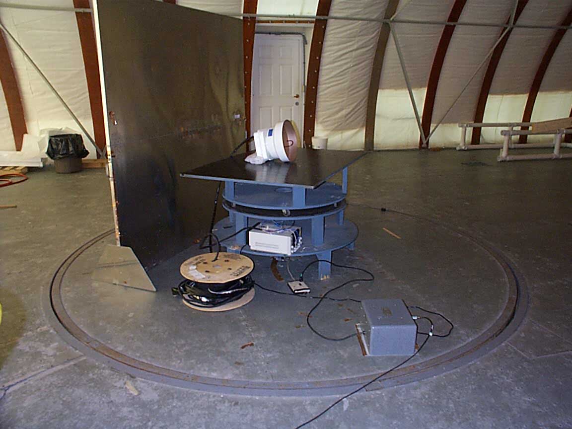
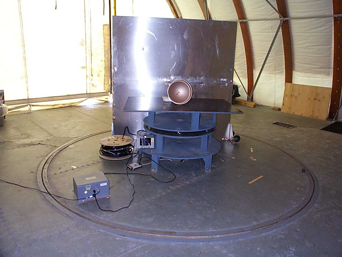
Microwave RF power density measurement for transmitters with high-gain antennas Background Regulatory limits for RF power density, in terms of microwatts/m 2 and similar units, are established under subparts 15.253 and 15.255 of FCC Part 15 Rules. According to Sanders, NTIA equation C.7b, far-field power density can be predicted from the field strength E (V/m) and the far-field impedance of free space 120π or 377Ω, from the basic equation P = V 2 /R as (1)S(W/m 2 ) = E(V/m) 2 /377 or, when the transmitter power in ERP is known, from the equation given in OET 65 page 21, (2) S(μW/cm 2 ) = 33.4 ERP/R 2 where R = the distance in meters from the transmitter antenna to the measuring antenna. Subparts 15.253 and 15.255 set the power density limits at a measurement distance of 3m. For high-gain antennas used at microwave frequencies, the 3m distance is likely to be within the antenna’s near field or Fresnel region. This can be confirmed from the equation for near-field boundary given in OET 65 (p. 27): (3) R nf = D 2 /4λ For a parabolic reflector (Cassegrain) antenna with D = 30cm and λ = 0.5 cm (about 60 GHz), equation (3) predicts a near-field boundary of R nf = 4.5m. The corresponding far-field boundary is given in OET 65 (page 29) as: (4) R ff = 0.6 D 2 /λ For the same parameters as above, equation (4) predicts a far-field or plane-wave boundary of R ff = 10.8m. It is important to know where the near-field and far-field boundaries exist with respect to the 3m measuring distance, because the validity of equations (1) and (2) break down in the near field. OET 65, page 46 notes: “...a readout device calibrated in units of power density does not read true power density if measurements are made in the near-field. This is because under plane-wave conditions, in which E, H, and power density are related by a constant quantity (the wave impedance which, for free space, is equal to 377 ohms), do not exist in the near-field where the wave impedance is complex and generally not known.” Fortunately, it is possible to predict power densities S in the near and far fields, as well as in the “transition region” in between, as a function of the transmitter output power P and distance from the transmitting antenna R. The equations are given in OET 65 pages 27 – 29 as follows: (5) at the surface of the antenna with aperture area A:S surface = 4P/A (6) in the near field, with antenna maximum dimension D:S nf = 16ηP/πD 2 , η = aperture efficiency (7) in the transition region R nf < R < R ff at distance R:S t = S nf R nf /R (8) in the far field or Fraunhofer region:S ff = PG/4πR 2 , G = transmitter antenna gain The equations (5) – (8) indicate that the variation of power density with distance R from the transmitter antenna is: a) constant from the antenna surface to the near-field boundary R nf ; b) decreases as 1/R in the transition region R nf < R < R ff ; c) decreases as 1/R 2 in the far field, for R > R ff . The equations and power density relationships are summarized and illustrated graphically in the diagram below. In cases where the measurement distance of 3m is closer to the transmitting antenna than the Fraunhofer region or the far field, the assumption a) that wave impedance is 377Ω, and b) the equat…
Text truncated - open the document above for the full version.
Contact Information
Applicant
Richard J Hughes(Engineering Manager)
Technical Contact
SierraComJanusz Majewski
[email protected]508-435-2400
70 Codman Hill Road · Hopkinton, Massachusetts · United States
Non-Technical Contact
SierraComJanusz Majewski
[email protected]508-435-2400
Test Firm
Intertek Testing Services NA Inc.Roland Gubisch
Technical Specifications
| # | Rule Parts | Frequency Range | Power Output |
|---|---|---|---|
| 1 | 15C | 60.25 GHz - 62.75 GHz | 3.20 mW |