PWPFAA2400RF Transceiver Module
Beissbarth GmbH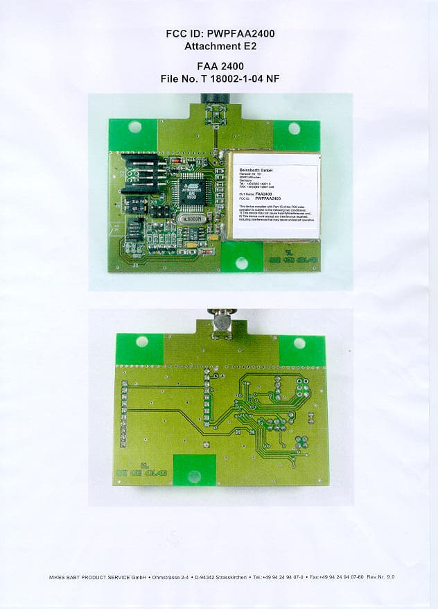
Click to zoom
Application Details
- Equipment Class
- DXX - Part 15 Low Power Communication Device Transmitter
- Date of Grant
- Oct 18, 2001
- Application Purpose
- Original Equipment
- Date of Application
- Oct 17, 2001
- Equipment Note
- RF Transceiver Module
- Frequency Range
- 2406.00000000 - 2478.00000000
- Company
- Beissbarth GmbH
- Country
- Germany
Documents & Files
Document Text
Text extracted from the exhibit documents filed with the FCC. Open a document above to read the original.
Users Manual
FAA2400 Seite 1 von 15 16/04/00 2.4GHz WIRELESS DATA TRANSCEIVER MODULE FAA2400 is a wireless transceiver module for half-duplex data transmission in the 2.4GHz ISM band. FAA2400 operates with digital data rates of more than 500kbps over distances of about 200m (line of sight) or 30m (inside buildings). FAA2400 allows the construction of 2.4GHz wireless links accordingly BAPT222 ZV125 in Germany and I-ETS-300440 in Europe and the corresponding international regulations in combination with a simple microcontroller. Features • Miniature module for PCB mount • Size (without contact pins) 33 x 30.5 x 8 mm³ • Mounting and electrical connection with contact pins (2.54mm grid) • BAPT222 ZV125 and I-ETS-300440 tested and approved, meets also other international regulations for 2.4GHz ISM • Worldwide registration for the 2.4GHz ISM band possible • Maximum halfduplex data rate of 500kbps • Modulation type 2FSK (2 Level Frequency Shift Keying) • Frequency range 2.4 bis 2.4835 GHz (up to 2.5 GHz also possible), PLL synthesizer • Frequency steps and frequency channels free programmable • Receive and transmit frequency programmable also while operating • Transmission power –30 to +5dBm typical (5 0 W) with simple DC control • Typical input sensitivity of –96dBm (Baudrate 200kbit/s) • Range of about 30m inside buildings and about 200m with line of sight (using 2.4GHz 0dBd antenna, full transmit output power) • Current consumption of typical 55mA in transmit and 50mA in receive mode at 3.2 to 6.0V • Standby mode for power saving • Logic inputs and outputs 3V CMOS compatible • Separate data input and output Note: Please take care for sufficient ESD protection when using the FAA2400 ! FAA2400 Seite 3 von 15 16/04/00 FAA2400 includes all necessary functions for wireless transmission of any digital baseband signal over 2.4GHz with 2FSK modulation, and for receiving a corresponding 2.4GHz signal and change it back to a digital baseband signal. Main parameters like frequency, transmission power and several operating modes can be controlled via digital and analog control lines. FAA2400 is a dual superhet receiver in receive mode . This allows a very good input sensitivity and selectivity. The 2FSK modulated RF signal between 2.400 and 2.4835GHz comes from the antenna pin over the RF filter and the Rx/Tx switch to the low noise amplifier (LNA). The amplified and filtered signal is mixed by the first mixer with the RF local oscillator (LO) frequency (RF VCO and PLL frequency synthesizer work as LO). The resulting first intermediate frequency (IF) is 323.0MHz. The RF LO frequency f L O1 for a given receive frequency f RF is determined by f L O1 = f RF − 323.0MHz (see section ”Programming the PLL Frequency Synthesizer”). The IF signal is filtered, amplified and mixed with a second local oscillator signal to the second IF of 5.7MHz. Frequency of second LO has to be f L O2 = 323.0MHz-5.7MHz = 317.3MHz. Second IF is amplified, filtered and limited to get a constant amplitude for demodulation. FSK demodulator and comparator deliver the demodulated baseband signal on pin DATA OUT. The RSSI output is an analog voltage as measure of the RF input power on the selected frequency. In transmit mode the frequency of the first IF is 2FSK modulated with the data signal from DATA IN. The modulated IF signal is amplitude regulated and mixed to the desired transmit frequency between 2.400 and 2.4835GHz. This is done by the transmit mixer and the second LO. Power amplifier (PA) delivers the necessary output power. The RF reaches pin ANTENNA over the Tx/Rx switch and a 2.4GHz bandpass. An analog DC voltage on TX POWER controls the output power from –30 to +5dBm typical. The frequency of IF LO is the same like receiving. RF LO programming is f L O1 = f RF − 317.3MHz (see section f L O1 = f RF − 317.3MHz „Programming the PLL Frequency Synthesizer”). STANDBY disables all functions and reduces the current consumption to a minimum. With changing from transmit to receive mode and back, after putting on DC supply and after STANDBY the PLL frequency synthesizer must be programmed (see section „Programming the PLL Frequency Synthesizer”). Programming is done like described above dependent on operating mode.
Attestation Statements
ATTESTATION STATEMENT FCC ID: PWPFAA2400 Transceiver Modul FAA2400 SUMMARY: All tests according to FCC Part Subpart C Paragraph 15.249 n - Performed The equipment under test n - Fulfills the general approval requirements of FCC Part Subpart C Paragraph 15.249 - MIKES BABT PRODUCT SERVICE GmbH - Responsible Engineer _____________________________ Nikolaus Fischer
Test Report
FCC ID: PWPFAA2400 TTI - P-G 009 / 98-00 TTI - P-G 089 / 94-50 File No. T 18002-1-05 NF , Page 1 of 15 MIKES BABT PRODUCT SERVICE GmbH Ohmstrasse 2-4 94342 Strasskirchen Tel.:+9424-9407-0 Fax:+9424-9407-60 Rev. No. 9.0 E M I S S I O N -- T E S T R E P O R T Test Report File No. : T 18002-1-05 NF ________________ Date : Sept. 13, 2001 of issue ________________ Type Designation:FAA 2400 ______________________________________________ Kind of Product:RF Tansceiver Modul (2.4 GHz) ______________________________________________ Applicant:Beissbarth GmbH ______________________________________________ Manufacturer:PSW Elektronik GmbH ______________________________________________ Licence holder:Beissbarth GmbH ______________________________________________ Address:Hanauer Straße 101 ______________________________________________ D-80993 München ______________________________________________ Test result accdg. to the regulation(s) at page 3 :Positive This test report with attachment consists of 28 pages. The test result only corresponds to the tested sample. It is not permitted to copy this report, in part or in full, without the permission of the test laboratory. File No. T 18002-1-05 NF , Page 2 of 15 MIKES BABT PRODUCT SERVICE GmbH Ohmstrasse 2-4 94342 Strasskirchen Tel.:+9424-9407-0 Fax:+9424-9407-60 Rev. No. 9.0 D I R E C T O R Y Page Documentation Directory2 ________ Test regulations3 ________ General information4-5 ________ Discovery of worst case condition6 ________ Equipment under Test14 ________ Summary15 ________ Test data Conducted emissions 10/150 kHz - 30 MHz7 ________ Spurious emissions (magnetic field) 10 kHz - 30 MHz8-9 ________ Spurious emissions (electric field) 30 MHz - 1000 MHz10 ________ Spurious emissions (electric field) 1 GHz - 18 GHz11 ________ Radiated power of the fundamental wave12 ________ Conducted power of the fundamental wave measured on13 the antenna terminals ________ Attachment A)Test dataA1-A8 ________ B)List of Test EquipmentB1 ________ C)Photos of the test setupC1-C2 ________ D)Technical description of the test sample-- (e.g. CDF, Declaration) ________ E)Photos of the EuTE1-E2 ________ F)Measurement Protocol for FCC, VCCI and AUSTEL-- ________ File No. T 18002-1-05 NF , Page 3 of 15 MIKES BABT PRODUCT SERVICE GmbH Ohmstrasse 2-4 94342 Strasskirchen Tel.:+9424-9407-0 Fax:+9424-9407-60 Rev. No. 9.0 T E S T R E G U L A T I O N S The tests were performed according to following regulations : o- EN 50081-1/ 2.1991 o- EN 50081-2/ 7.1993 -------------------------------------------------------------------------------- o- EN 55011/ 3.1991o- Group 1o- Group 2 o- class Ao- class B o- EN 55014/ 4.1993o- Household appliances and similar o- tools o- Semiconductor devices o- EN 55014 / A2:1990 o- EN 55104/ 5.1995Category: o- EN 55015 / A1:1990 o- EN 55015 / 12.1993 o- EN 55022 / 5.1995o- class Ao- class B o- prEN 55103-1/ 3.1995 o- prEN 50121-3-2/ 3.1995 o- EN 60601-1-2/ 4.1994 o- VCCIo- class 1o- class 2 n- Part 15 Subpart C (15.249) n- Part 15 Subpart C (15.209) File No. T 18002-1-05 NF , Page 4 of 15 MIKES BABT PRODUCT SERVICE GmbH Ohmstrasse 2-4 94342 Strasskirchen Tel.:+9424-9407-0 Fax:+9424-9407-60 Rev. No. 9.0 A D D R E S S O F T H E T E S T L A B O R A T O R Y n-MIKES BABT PRODUCT SERVICE GmbH Ohmstrasse 2-4 D - 94342 Strasskirchen o-______________________________________ ______________________________________ ______________________________________ ______________________________________ E N V I R O N M E N T A L C O N D I T I O N S Temperature:15-35 ° C ____________ Humidity45-60 % ____________ Atmospheric pressure 860-1060 mbar ____________ POWER SUPPLY SYSTEM UTILIZED Power supply systemo 230V/50 Hz / 1φn 5.0 V DC o 400V/50 Hz 3PEo 400V/50 Hz 3NPE STATEMENT OF MEASUREMENT UNCERTAINTY SHORT DESCRIPTION OF THE EQUIPMENT UNDER TEST (EuT) The DC-operated transceiver modul FAA 2400 is designed for data transmission purposes at the frequency Band 2.400 GHz – 2.4835 GHz. Number of received/tested samples:1 / 1 Serial Number:Pre Production Sample DEFINITIONS FOR SYMBOLS USED IN THIS TEST REPORT n The black square indicates that the listed condition, standard or equipment is applicable for this report. o Blank box indicates that the listed condition, standard or equipment was not applicable for this report. File No. T 18002-1-05 NF , Page 5 of 15 MIKES BABT PRODUCT SERVICE GmbH Ohmstrasse 2-4 94342 Strasskirchen Tel.:+9424-9407-0 Fax:+9424-9407-60 Rev. No. 9.0 M E A S U R E M E N T P R O T O C O L F O R F C C , V C C I A N D A U S T E L Test Methodology Conducted and radiated emission testing is performed according to the procedures in International Special Committee on Radio Interference (CISPR) Publication 22 (1993), European Standard EN 55022 and Australian Standard AS 3548 (which are based on CISPR 22). The Japanese standard, "Voluntary Control Council for Interference (VCCI) by Data Processing Equipment and Electronic Office Machines, Technical Requirements" is technically equivalent to CISPR 22 (1993). For official compliance, a conformance report must be sent to and accepted by the VCCI. In compliance with FCC Docket 92-152, "Harmonization of Rules for Digital Devices Incorporate International Standards", testing for FCC compliance may be done following the ANSI C63.4-1992 procedures and using the FCC limits or the CISPR 22 Limits. Measurement Uncertainty The test system for conducted emissions is defined as the LISN, tuned receiver or spectrum analyzer, and coaxial cable. The test system for radiated emissions is defined as the antenna, the pre-amplifier, the spectrum analyzer and the coaxial cable. These test systems have a measurement uncertainty of ±4.5 dB. The equipment comprising the test systems are calibrated on an annual basis. Justification The Equipment Under Test (EuT) is configured in a typical user arrangement in accordance with the manufacturer's instructions. A cable is connected to each available port and either terminated with a peripheral into it’…
Text truncated - open the document above for the full version.
Test Setup Photos
FCC ID: PWPFAA2400 Attachment C1 of C2: Photo documentation File No.: T 18002-1-04 NF MIKES BABT PRODUCT SERVICE GmbH w Ohmstrasse 2-4 w D-94342 Strasskirchen w Tel.:+49 94 24 94 07-0 w Fax:+49 94 24 94 07-60 Rev.No. 9.0 Test-Setup: SPURIOUS EMISSIONS (electric field) 30 MHz - 1000 MHz FCC ID: PWPFAA2400 Attachment C2 of C2: Photo documentation File No.: T 18002-1-04 NF MIKES BABT PRODUCT SERVICE GmbH w Ohmstrasse 2-4 w D-94342 Strasskirchen w Tel.:+49 94 24 94 07-0 w Fax:+49 94 24 94 07-60 Rev.No. 9.0 Test-Setup: SPURIOUS EMISSIONS (electric field) 1000MHz – 10-harmonics
Contact Information
Applicant
Stefan Schommer(Development)
Test Firm
MIKES BABT Product Service GmbHHarald Buchwald
Technical Specifications
| # | Rule Parts | Frequency Range | Power Output | Emission | Tolerance |
|---|---|---|---|---|---|
| 1 | 15C | 2.41 GHz - 2.48 GHz | 10.00 mW | 1M00F7D | 50.0000000000 ppm |
Other Applications from Beissbarth GmbH

PWPGTR-EASY-2400
Oct 27, 2005Radio Module for wheel alignment system
Equipment Class
DXX - Part 15 Low Power Communication Device Transmitter