PWYJT27TX990001:16 BATTLE MACHINE
Jada Toys Company Limited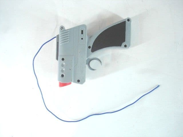
Click to zoom
Application Details
- Equipment Class
- DXX - Part 15 Low Power Communication Device Transmitter
- Date of Grant
- May 10, 2010
- Application Purpose
- Original Equipment
- Date of Application
- May 10, 2010
- Equipment Note
- 1:16 BATTLE MACHINE
- Frequency Range
- 27.14500000 - 27.14500000
- Company
- Jada Toys Company Limited
- Country
- Hong Kong
Documents & Files
Document Text
Text extracted from the exhibit documents filed with the FCC. Open a document above to read the original.
Operational Description
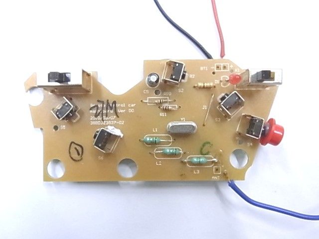
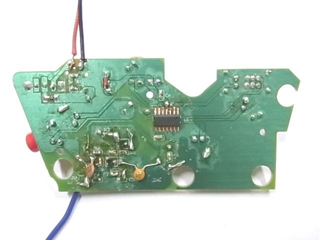
JADA TOYS CO., LTD Project No. : 83196,83197, 84712,84713, 84045 Model Name : 1:16 Battle Machine RC (Single and Twin Pack) Transmitter and Receiver Circuitry Operating Description In Transmit Mode: Transmitter: When the power switch S1 turns to “ON”, Q1 and the Y1 crystal produce a carrier frequency, press one of the keys FIRE, R, L, F, B, The Encode IC1 U12501B pin8 gives the signal out to Q2, and mixed the carrier frequency signal, after Q2 amplifier the signal and transmit from antenna. There are three sets of modulation signal can be selected by Band Selecting Switch S2. A 9V battery supplies energy. In Receive Mode: Receiver: When the power switch S1 turns to “ON”, The modulation signal receive from the antenna and pass to local oscillation and demodulation from Q1, The encoding signal transfer to Signal Amplifier IC IC1 SC010, Encoding IC IC2 SN8P2501B and Voice IC IC3 SNC113, after decoding the direct control signal go to the motor driver unit. The Q11,Q12,Q13,Q14,Q115 & Q16 control motor M2 to control Forward and Backward function, the Q5~Q10 control motor M1 to control Left and Right function. In Auto Mode: Receiver: When the Auto Mode Switch S1 turns to “AUTO”, the Encoder IC IC2 SN8P2501B Pin 12, 13 and 14 communicate with Voice IC IC3SNC113 Pin 3, 4 and 18, and controls motor driver of M1 and M2 to perform the Auto motion. In Battle Mode: Receiver - Fire Action: The modulation signal receive form the antenna through Q1 and Signal Amplifier IC IC1 SC010 to Encoding IC IC2 SN8P2501B, the Encoding IC controls LED D1 lights up and IR emitter D2 to give out an Infrared signal. Receiver - Being Hit: The IR Receiver HM338 receive an IR signal and pass to Pin 2 of Voice IC SNC113. The Voice IC controls Health indicating LED D3, D4 and D5 and Speaker to play sound FX. Receiver - Reset: Press the Reset switch S3 to reset the Encoding IC SN8P2501B and Voice IC SNC113. The Health Indicating LED D3, D4 and D5 will back to original. Energy is supplied by 4x AA size (1.5V) battery..
Schematics
ANT 9V BATTERY C7 103 C8 100P C6 100P C3 47P C5 103 C4 56P Y1 27.145MHZ D1 LED (3MM) Q2 C945 Q1 C945 R5 220K R2 4K7 R1 0R R6 10R R8 33K R9 100R L1 1uH L2 1uH RLBF S1 (1P2T) ON/OFF R7 15K C11 203 FIRE L3 8.2UH C1 47U C2 103 R1 330R D2 3.9V R2 1K5 1 2 3 4 5 6 78 9 10 11 12 13 14 R6 10K R6 100R IC1 SN8P2501B (SOP14) P2.0 P2.1 P2.2 VDD PL.3/MIN PL.2/XOUT PL.L/RST/VPP P2.3 P2.4 P2.5 GND P0.0/INT0 P1.0 P5.4/PWM0 SS-12F24-G4 1 2 4 3 S2 BAND (A/B/C) SS-23D24-G10 C9 103 C10 103 JADA TOYS CO., LTD. 1/16 BATTLE MACHINE TX CIRCUIT DIAGRAM (27M) 2010/05/05 Cx 202 PDF 文件使用 "pdfFactory Pro" 试用版本创建 www.fineprint.cn
Test Report
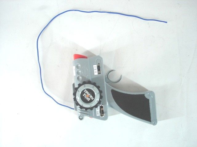
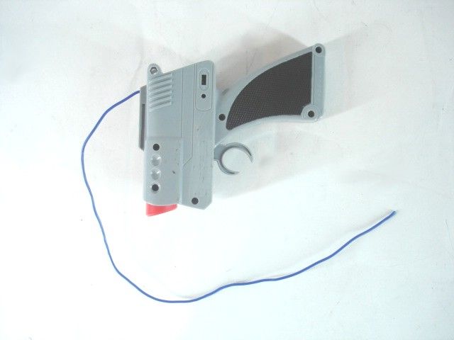
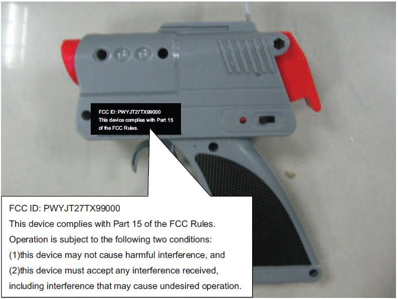
TEST REPORT Report No. : AM0017566 Date : 2010-05-10 Page 1 of 11 FCC ID: PWYJT27TX99000 This document is issued subject to CMA Testing standard TEARMS AND CONDITIONS, and shall not be reproduced except in full or with written approval by CMA Testing. CMA Industrial Development Foundation Limited Room 1302, Yan Hing Centre, 9-13 Wong Chuk Yeung St.., Fo Tan, Shatin, Hong Kong. Tel: (852) 2698 8198 Fax: (852) 2695 4177 E-mail: [email protected] Web Site: http://www.cmatcl.com Application No. : LM220349 Applicant : Jada Toys Co., Ltd. Unit 305-308, 3/F., Tower B, New Mandarin Plaza, 14 Science Musuem Road, Tsim Sha Tsui East, Kowloon, Hong Kong Sample Description : One (1) submitted sample(s) stated to be 1:16 Battle Machine of Model No. 84712, 83196, 83197, 84713 and 84045 Radio Frequency : 27.145MHz Transmitter Rating : 1 x 9V size battery No. of submitted sample : Two (2) piece(s) Date Received : 2010-03-29. Test Period : 2010-03-31 to 2010-05-07. Test Requested : FCC Part 15 Certification. Test Method : 47 CFR Part 15 (10-1-09 Edition) ANSI C63.4 – 2003 Test Result : See attached sheet(s) from page 2 to 11. Conclusion : The submitted sample was found to comply with requirement of FCC Part 15 Subpart C. Remark : All five models are the same in circuitry and components; and therefore model 84712 was chosen to be the representative of the test sample. There are three channels and channel B was tested. The different of three channels is the pattern of coding. For and on behalf of CMA Industrial Development Foundation Limited Authorized Signature : ____________________________________________________ Mr. Wong Lap-pong, Andrew Assistant Manager Electrical Division TEST REPORT Report No. : AM0017566 Date : 2010-05-10 Page 2 of 11 FCC ID: PWYJT27TX99000 This document is issued subject to CMA Testing standard TEARMS AND CONDITIONS, and shall not be reproduced except in full or with written approval by CMA Testing. CMA Industrial Development Foundation Limited Room 1302, Yan Hing Centre, 9-13 Wong Chuk Yeung St.., Fo Tan, Shatin, Hong Kong. Tel: (852) 2698 8198 Fax: (852) 2695 4177 E-mail: [email protected] Web Site: http://www.cmatcl.com Table of Contents 1 General Information............................................................................................................................. 3 1.1 General Description ..................................................................................................................... 3 1.2 Location of the test site................................................................................................................ 4 1.3 List of measuring equipment ....................................................................................................... 5 1.4 Measurement Uncertainty............................................................................................................ 5 2 Description of the radiated emission test............................................................................................. 6 2.1 Test Procedure ............................................................................................................................. 6 2.2 Test Result ................................................................................................................................... 6 2.3 Radiated Emission Measurement Data ........................................................................................ 7 3 Description of the Line-conducted Test .............................................................................................. 8 3.1 Test Procedure ............................................................................................................................. 8 3.2 Test Result ................................................................................................................................... 8 3.3 Graph and Table of Conducted Emission Measurement Data .................................................... 8 4 Photograph ........................................................................................................................................... 9 4.1 Photographs of the Test Setup for Radiated Emission and Conducted Emission ....................... 9 4.2 Photographs of the External and Internal Configurations of the EUT ........................................ 9 5 Supplementary document .................................................................................................................. 10 5.1 Bandwidth.................................................................................................................................. 10 5.2 Duty cycle .................................................................................................................................. 10 5.3 Transmission time...................................................................................................................... 10 6 Appendices ........................................................................................................................................ 11 TEST REPORT Report No. : AM0017566 Date : 2010-05-10 Page 3 of 11 FCC ID: PWYJT27TX99000 This document is issued subject to CMA Testing standard TEARMS AND CONDITIONS, and shall not be reproduced except in full or with written approval by CMA Testing. CMA Industrial Development Foundation Limited Room 1302, Yan Hing Centre, 9-13 Wong Chuk Yeung St.., Fo Tan, Shatin, Hong Kong. Tel: (852) 2698 8198 Fax: (852) 2695 4177 E-mail: [email protected] Web Site: http://www.cmatcl.com 1 General Information 1.1 General Description The equipment under test (EUT) is a transmitter for 1:16 Battle Machine. It operates at 27.145MHz and the oscillation of radio control is generated by a crystal. The EUT is powered by 1 x 9V size battery. There are two control triggers, one "Fire" button and one coding switch on the EUT. The coding switch is used to change coding to prevent interference.…
Text truncated - open the document above for the full version.
Test Report
Workform Job No. Document Ref No: WF-EL-EMC-15 Page of Issue Date: 2010-01-11 Edition: 1 (Amd 2) Bandwidth Plot Bandwidth 1
Test Report
Workform Job No. Document Ref No: WF-EL-EMC-15 Page of Issue Date: 2010-01-11 Edition: 1 (Amd 2) Duty Cycle Duty Cycle 1 Duty Cycle 2 Workform Job No. Document Ref No: WF-EL-EMC-15 Page of Issue Date: 2010-01-11 Edition: 1 (Amd 2) Duty Cycle Duty Cycle 3
Contact Information
Applicant
Dennis Suen(Assistan General Manager)
Test Firm
CMA Industrial Development Foundations LimitedStephen Lam
Technical Specifications
| # | Rule Parts | Frequency Range | Power Output |
|---|---|---|---|
| 1 | 15C | 27.145 MHz - 27.145 MHz | - |
Other Applications from Jada Toys Company Limited
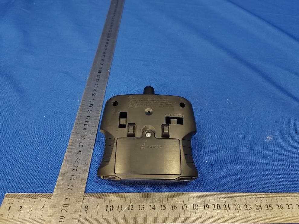
PWYJT24TX99062
May 26, 2026BTM 1/16 RC, FAST & FURIOUS 1/16 RC, Hollywood Rides 1/16 RC, PINK SLIP 1/16 RC, Hyper Charger 1/16 RC
Equipment Class
DXX - Part 15 Low Power Communication Device Transmitter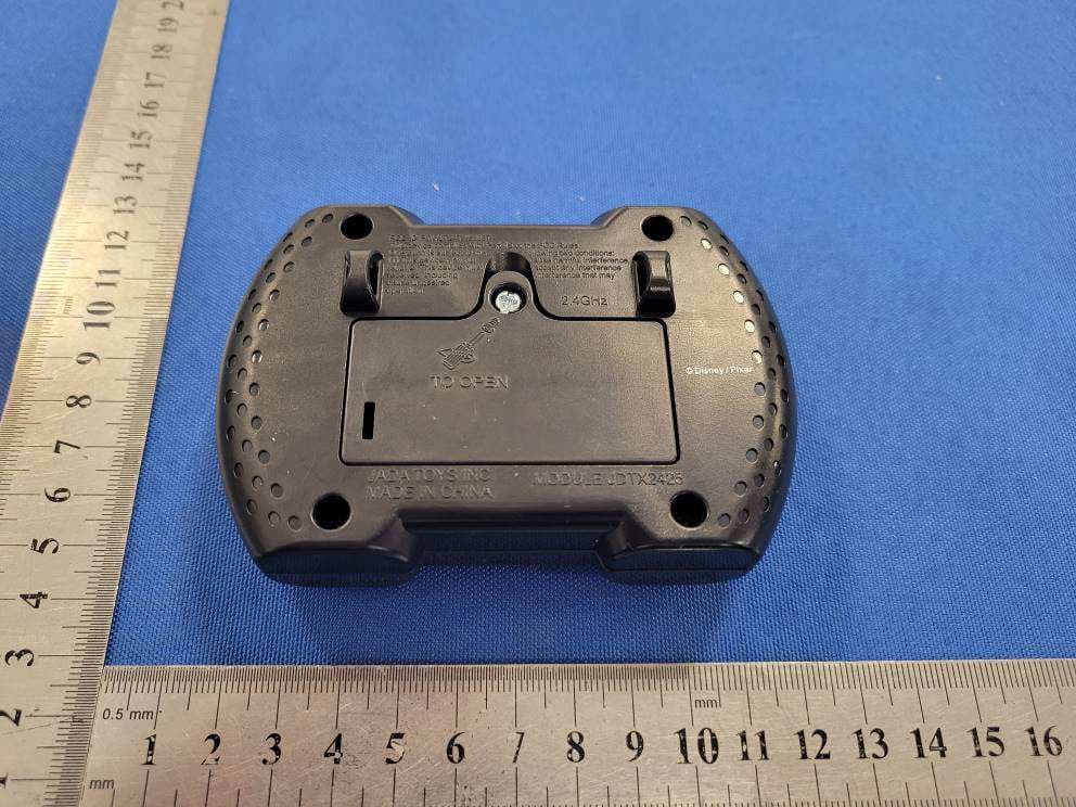
PWYJT24TX99057
Apr 27, 2026Disney Pixar RC Cars, R/C Lightning Mcqueen
Equipment Class
DXX - Part 15 Low Power Communication Device Transmitter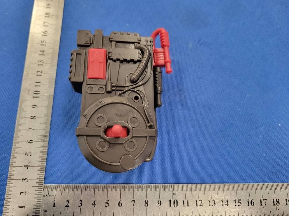
PWYJT24TX99059
Apr 27, 202611 inches Ghostbuster RC, Stay Puft Marshmallow Man RC
Equipment Class
DXX - Part 15 Low Power Communication Device Transmitter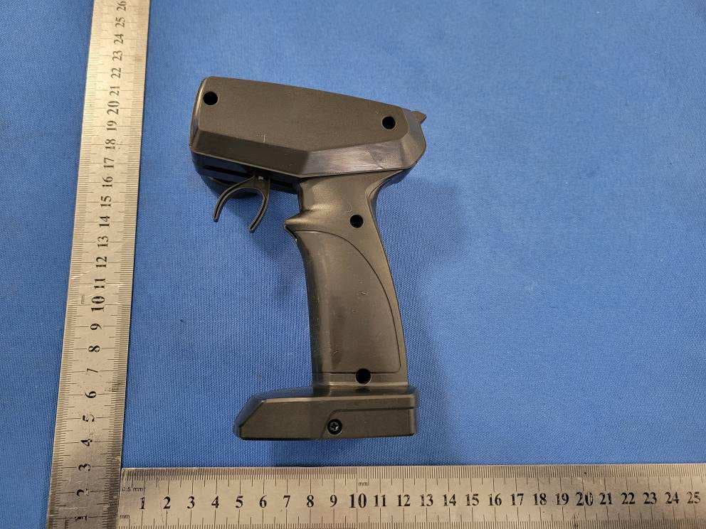
PWYJT24TX99058
Apr 06, 20261/16 F1 McLaren RC
Equipment Class
DXX - Part 15 Low Power Communication Device Transmitter
PWYJT24TX99056
Dec 10, 2025Star Wars AT-AT Walker RC, Star Wars AT-RT Walker RC
Equipment Class
DXX - Part 15 Low Power Communication Device Transmitter