PWYJT49RX85008RC Car Receiver
Jada Toys Company Limited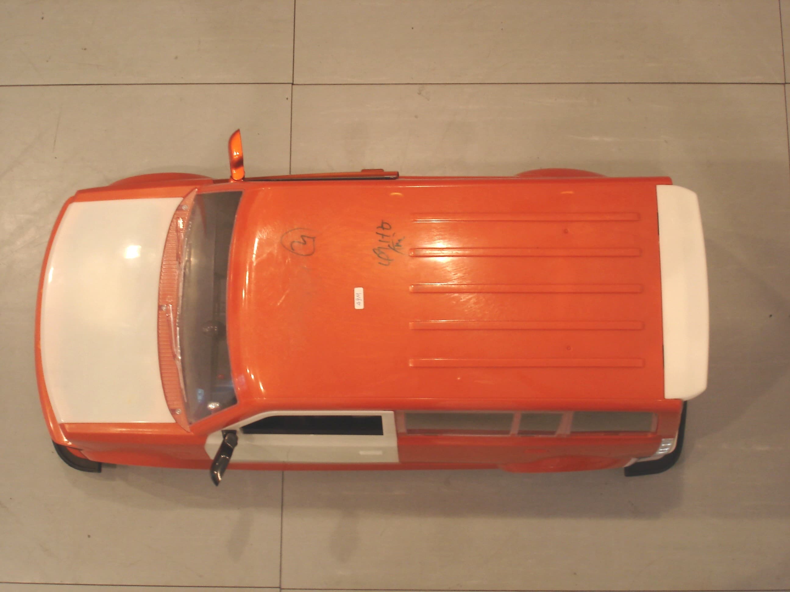
Click to zoom
Application Details
- Equipment Class
- CRR - Superregenerative Receiver
- Date of Grant
- Jun 22, 2005
- Application Purpose
- Original Equipment
- Date of Application
- Jun 22, 2005
- Equipment Note
- RC Car Receiver
- Frequency Range
- 49.86000000 - 49.86000000
- Company
- Jada Toys Company Limited
- Country
- Hong Kong
Documents & Files
Document Text
Text extracted from the exhibit documents filed with the FCC. Open a document above to read the original.
Cover Letter(s)
American Telecommunications Certification Body Inc. 6731 Whittier Ave, McLean, VA 22101 June 21, 2005 RE: Jada Toys Co., Ltd. FCC ID: PWYJY49RX84008 After a review of the submitted information, I have a few comments on the above referenced Application. 1) The device should be tested up to 1 GHz. However test equipment does not appear to show measurement equipment (antennas) to that frequency range. Please review. 2) According to the users manual, the device may have an external cable attached for playing music. Is the RX operation in this mode. If so, has this mode been checked in effort to ensure worse case results were obtained? Timothy R. Johnson Examining Engineer mailto: [email protected] The items indicated above must be submitted before processing can continue on the above referenced application. Failure to provide the requested information may result in application termination. Correspondence should be considered part of the permanent submission and may be viewed from the Internet after a Grant of Equipment Authorization is issued. Please do not respond to this correspondence using the email reply button. In order for your response to be processed expeditiously, you must submit your documents through the AmericanTCB.com website. Also, please note that partial responses increase processing time and should not be submitted. Any questions about the content of this correspondence should be directed to the sender.
Cover Letter(s)
Dear Timothy, For your enquiry, below is some information about these applications : For FCC ID : PWYJT49TX85000 1) The device appears to be tested to approximately 500 MHz. However test equipment does not appear to show measurement equipment (antennas) to that frequency range. Please review. In P.5 of the test report, 1.3 List of measuring equipment, we've got a Broadband Antenna (Bilog Antenna) which is calibrated from 27MHz - 2000MHz for measuring high frequency. For FCC ID : PWYJT49RX85008 1) The device should be tested up to 1 GHz. However test equipment does not appear to show measurement equipment (antennas) to that frequency range. Please review. Yes, according to Part 15 Section 15.33 (b) (1), we have investigated up to 1GHz, since this Receiver only has emission up to about 150MHz, so only those highest emissions were presented in the data table. I have revised the Test Report including this statement in P.6, 2.2 Test Result (as attached) In P.5 of the test report, 1.3 List of measuring equipment, we've got a Broadband Antenna (Bilog Antenna) which is calibrated from 27MHz - 2000MHz for measuring high frequency. 2) According to the users manual, the device may have an external cable attached for playing music. Is the RX operation in this mode. If so, has this mode been checked in effort to ensure worse case results were obtained? Yes, we have connected the external cable for making the measurement and it is the worse case, since the line-in jack is inside the car (please see the attached photo), those test setup photos or external photos previously submitted cannot shown clearly enough. Hope this information could help. Thanks and Best Regards, Tommy PWYJT49RX85008 TestRpt(Revised)1.pdf From: "Electrical EMC" <[email protected]> To: <[email protected]> Cc: "Danny Chui" <DannyChui ...snip... EMC" <[email protected]> Subject: Enquiry about Jada (FCC ID : PWYJT49TX85000,FCC ID : PWYJT49RX85008) Page 1 of 2In 6/21/2005Printed for "Timothy R. Johnson" <[email protected]> Receiver Internal1.JPG Page 2 of 2In 6/21/2005Printed for "Timothy R. Johnson" <[email protected]>
Operational Description
Energy of the car is supplied by DC9.6V rechargeable battery. to be amplified by IC3. D2,D3,R34,R35,Q16,D14 is the current of L&R motor run center. D17~D20 is LED in the front of the car. D21~D24 is LED in the back of the car. D16 is LED of lock point out . ANTENNA AND GROUND CIRCUITRY: The TX use an external 20-inch stretch out and draw back antenna, the car use an external 8-inch rod antenna, the antenna is inductively coupled, the unit relies on the Ground trace of the printed circuit board, No external ground is provided. IC1(SPRC206A) is a remote control decoder. IC2(EST-061) is a series of single channel voice IC. IC3(LM386) is a low voltage audio power amplifier.Q9~Q14 is the current driver of the left&right motor.Q22~Q25,RL1~RL4 is the current driver of the forward&back motor.Q17~Q20,R42~R47, C42 is the current temperature safeguard of F&B motor. Photo jack can make the signal of the MP3 DC9V(AAx6) Alkaline Battery supplies energy. IN RECEIVE MODE: The receiver part is using a supper regenerator circuit and Q1 is the supper regenrator&detector. forward key,back key,left key,right key the transmit frequency is oscillated by Y201 and mixed with the encoded signal from P3.2(pin8) of IC201 by Q201,then coupled through T201,L203 to antenna. SW202 is speed select switch , It make the car have three speed. The low pass filter made up of C201,C202,T201,L203,which is connected to the antenna. Early Light Industrial Co., Ltd. Circuit Description After TX unit is switched SW201 "ON" and press the lock key,horn key, music1 key, music2 key, Project No: #90230 Model Name: 1:6 R/C Car IN TRANSMIT MODE: Electronics Department Frequency: 27.145MHZ&49.860MHZ (USA) REV: 00 Prepareed By: QS Lee Date: 10-May-05 TEL:(China) : 86-755-8465111 EXT: 456
Schematics
1-6 Car 27M&49M RX (FCC).sch-1 - Sat May 14 16:41:21 2005
Test Report
TEST REPORT Report No. : AF013017-001 Date : 2005 June 16 For and on behalf of CMA Testing and Certification Laboratories Authorized Signature : Page 1 of 11 Danny Chui EMC Engineer - EL. Division FCC ID : PWYJT49RX85008 This document shall not be reproduced either in full or in part except with written approval by the Authorized Representative of CMA Testing. Room 1302, Yan Hing Centre, 9-13 Wong Chuk Yeung St.., Fo Tan, Shatin, Hong Kong. Tel: (852) 2698 8198 Fax: (852) 2695 4177 E-mail: [email protected] Web Site: http://www.cmatcl.com Application No. : LF209305(8) Applicant : Jada Toys Co. Ltd Unit 901, 9/F., Energy Plaza, 92 Granville Road, TST East, Kowloon, Hong Kong. Sample Description : One(1) submitted sample stated to be 1:6 Dub City RC car of Model No. 83008 Rating : 9.6V rechargeable battery No. of submitted sample : Two (2) piece(s)*** Date Received : Test Period : Test Requested : Test Method : Test Result : Conclusion : 2005 May 26 2005 May 26 – 2005 June 06 FCC Part 15 Certification FCC Rules and Regulations Part 15 – July 2004 ANSI C63.4 – 2003 See attached sheet(s) from page 2 to 11. The submitted sample was found to comply with requirement of FCC Part 15 Subpart B. TEST REPORT Report No. : AF013017-001 Date : 2005 June 16 Page 2 of 11 FCC ID : PWYJT49RX85008 This document shall not be reproduced either in full or in part except with written approval by the Authorized Representative of CMA Testing. Room 1302, Yan Hing Centre, 9-13 Wong Chuk Yeung St.., Fo Tan, Shatin, Hong Kong. Tel: (852) 2698 8198 Fax: (852) 2695 4177 E-mail: [email protected] Web Site: http://www.cmatcl.com Table of Contents 1 General Information .................................................................................................................................. 3 1.1 General Description ........................................................................................................................... 3 1.2 Location of the test site ...................................................................................................................... 4 1.3 List of measuring equipment.............................................................................................................. 5 2 Description of the radiated emission test .................................................................................................. 6 2.1 Test Procedure ................................................................................................................................... 6 2.2 Test Result ......................................................................................................................................... 6 2.3 Radiated Emission Measurement Data .............................................................................................. 7 3 Description of the Line-conducted Test .................................................................................................... 8 3.1 Test Procedure ................................................................................................................................... 8 3.2 Test Result ......................................................................................................................................... 8 3.3 Graph and Table of Conducted Emission Measurement Data ........................................................... 8 4 Photograph ................................................................................................................................................ 9 4.1 Photographs of the Test Setup for Radiated Emission and Conduction Emission............................. 9 4.2 Photographs of the External and Internal Configurations of the EUT............................................... 9 5 Supplementary document ......................................................................................................................... 10 5.1 Bandwidth ........................................................................................................................................ 10 5.2 Duty Cycle ....................................................................................................................................... 10 6 Appendices ............................................................................................................................................... 11 TEST REPORT Report No. : AF013017-001 Date : 2005 June 16 Page 3 of 11 FCC ID : PWYJT49RX85008 This document shall not be reproduced either in full or in part except with written approval by the Authorized Representative of CMA Testing. Room 1302, Yan Hing Centre, 9-13 Wong Chuk Yeung St.., Fo Tan, Shatin, Hong Kong. Tel: (852) 2698 8198 Fax: (852) 2695 4177 E-mail: [email protected] Web Site: http://www.cmatcl.com 1 General Information 1.1 General Description The equipment under test (EUT) is a superregenerative for 1:6 Dub City RC car. Operating at 49.860MHz which is controlled by LRC circuit. The EUT is powered by a 9.6V rechargeable battery. When it switchs on, it will receive a different radio signal from the transmitter continuously. The brief circuit description is listed as follows : - Q1 and associated circuit act as superregenerative receiver. - IC1 and associated circuit act as remote control decoder. - IC2 and associated circuit act as single channel voice IC. - IC3 and associated circuit act as low voltage audio power amplifier. - Q9-Q14 and associated circuit act as current driver of the left and right motors. - Q22-Q25, RL1-RL4 and associated circuit act as current driver of the forward and backward motors. TEST REPORT Report No. : AF013017-001 Date : 2005 June 16 Page 4 of 11 FCC ID : PWYJT49RX85008 This document shall not be reproduced either in full or in part except with written approval by the Authorized Representative of CMA Testing. Room 1302, Yan Hing Centre, 9-13 Wong Chuk Yeung St.., Fo Tan, Shatin, Hong Kong. Tel: (852) 2698 8198 Fax: (852)…
Text truncated - open the document above for the full version.
Contact Information
Applicant
Dennis Suen(Assistan General Manager)
Technical Contact
CMA Testing and CertificationDanny Chui
[email protected]852-2690-8251
Room 1302, Yan Hing Centre · Fo Tan, Shatin · Hong Kong
Non-Technical Contact
CMA Testing and CertificationDanny Chui
[email protected]852-2690-8251
Test Firm
CMA Industrial Development Foundations LimitedAndrew Wong
Technical Specifications
| # | Rule Parts | Frequency Range | Power Output |
|---|---|---|---|
| 1 | 15B | 49.86 MHz - 49.86 MHz | - |
Other Applications from Jada Toys Company Limited
PWYJT24TX99062
May 26, 2026BTM 1/16 RC, FAST & FURIOUS 1/16 RC, Hollywood Rides 1/16 RC, PINK SLIP 1/16 RC, Hyper Charger 1/16 RC
Equipment Class
DXX - Part 15 Low Power Communication Device Transmitter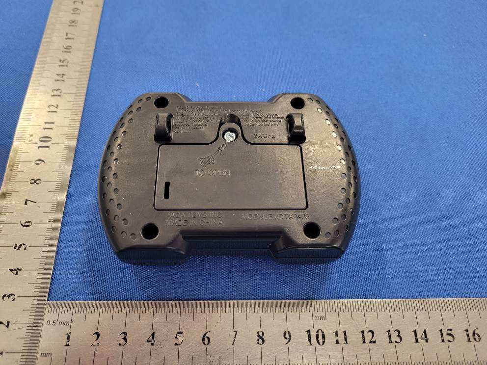
PWYJT24TX99057
Apr 27, 2026Disney Pixar RC Cars, R/C Lightning Mcqueen
Equipment Class
DXX - Part 15 Low Power Communication Device Transmitter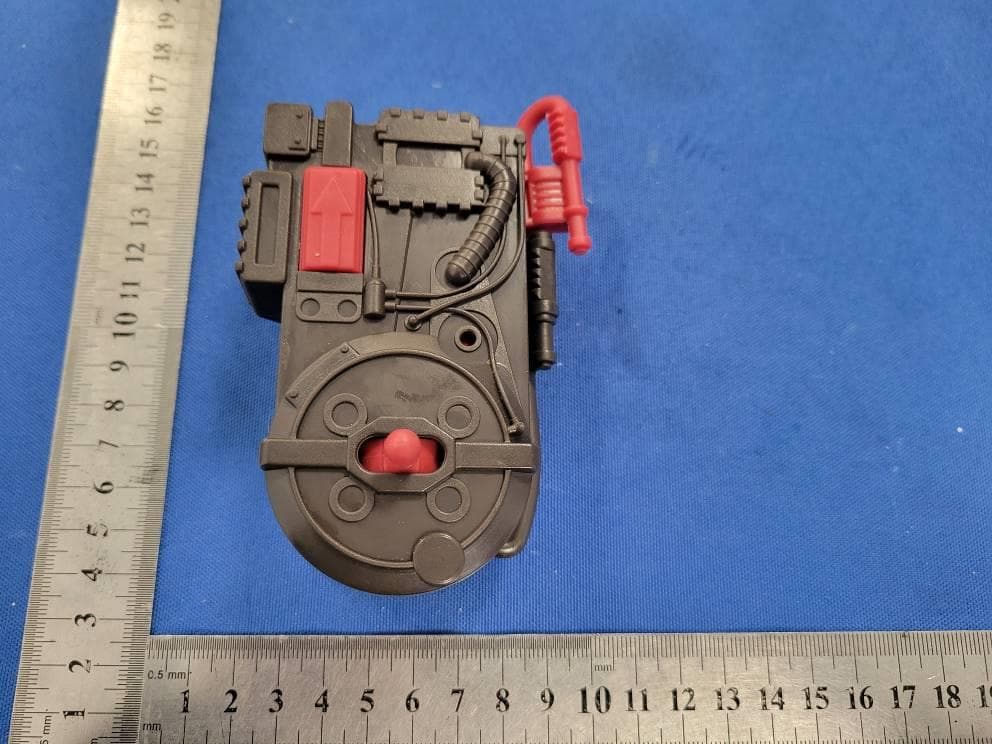
PWYJT24TX99059
Apr 27, 202611 inches Ghostbuster RC, Stay Puft Marshmallow Man RC
Equipment Class
DXX - Part 15 Low Power Communication Device Transmitter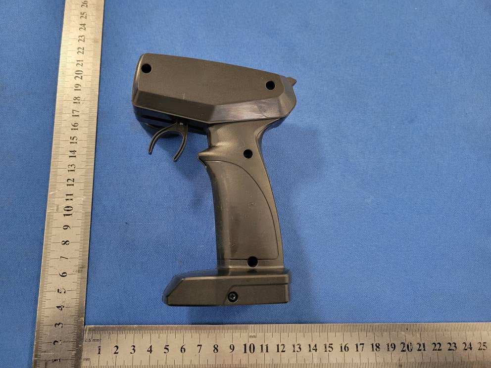
PWYJT24TX99058
Apr 06, 20261/16 F1 McLaren RC
Equipment Class
DXX - Part 15 Low Power Communication Device Transmitter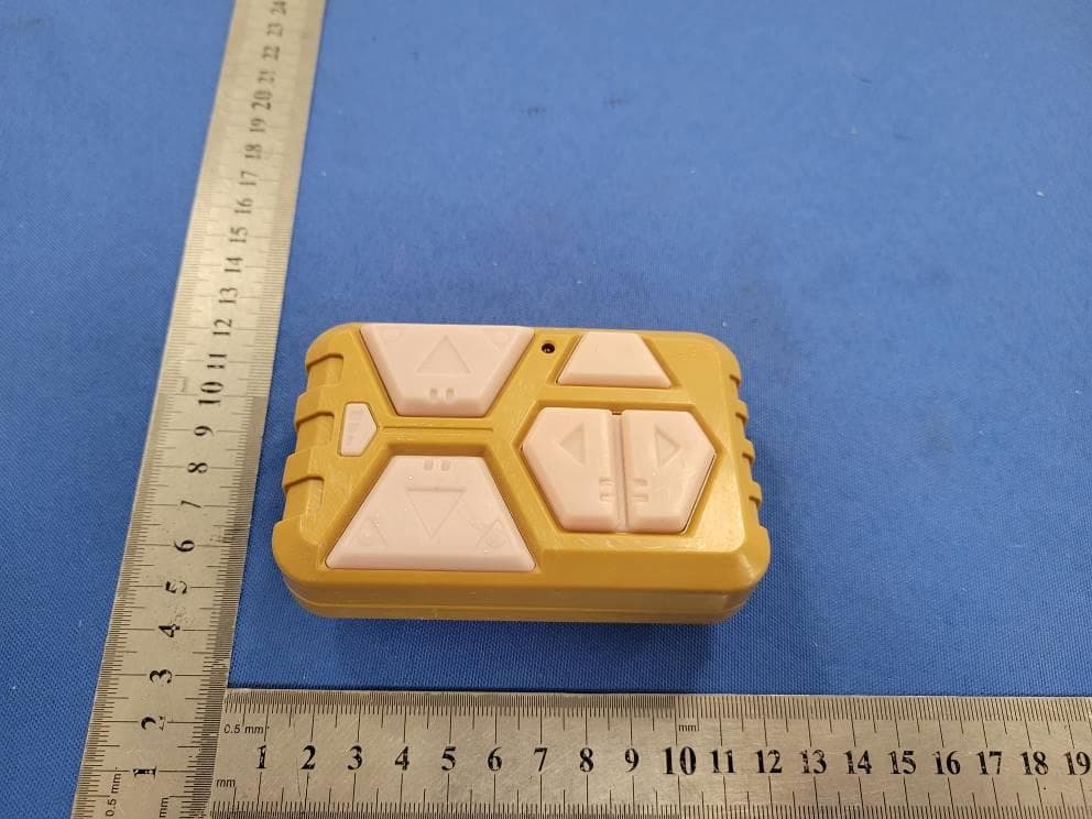
PWYJT24TX99056
Dec 10, 2025Star Wars AT-AT Walker RC, Star Wars AT-RT Walker RC
Equipment Class
DXX - Part 15 Low Power Communication Device Transmitter