PXDGI0011092001Data Radio Module
Guardian Instruments, Inc.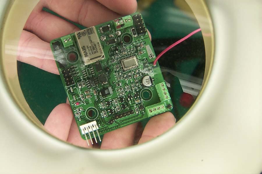
Click to zoom
Application Details
- Equipment Class
- DXX - Part 15 Low Power Communication Device Transmitter
- Date of Grant
- Jan 31, 2002
- Application Purpose
- Original Equipment
- Date of Application
- Jan 31, 2002
- Equipment Note
- Data Radio Module
- Frequency Range
- 902.00000000 - 928.00000000
- Company
- Guardian Instruments, Inc.
- Country
- United States
Documents & Files
Document Text
Text extracted from the exhibit documents filed with the FCC. Open a document above to read the original.
Users Manual
Guardian Instruments, Inc. 3585 County Rd. 272 #600, Leander, TX 78641 512-260-3554(phone) 512-260-3755(fax) OPERATIONS and TEST MANUAL PN: 4952-002 Radios Revision 1.0 Manual for 916.5 MHz and 914 MHz Radios Released 8/1/01 Regulatory Statement This device complies with part 15 of the FCC Rules. Operation is subject to the following two conditions: (1) This device may not cause harmful interference, and (2) this device must accept any interference received, including interference that may cause undesired operation. Warning Any modifications to this device without the express written consent of the party responsible for it’s compliance could void the user’s authority to operate the equipment! Power Requirements: Input Power Requirements: 6-30 VDC Input Current Drain: <750 ma with Relay Energized and Backlighting ON Mounting: Step1. Use #6 nylon screws to rigidly attach PCB assembly to mount plate. Use Locktite 242 to all screws. Step 2. Place the screws in the 4 mounting holes in the PCB and tighten to 5 ft-lbs. Programming: Step 1. Use the software provided with the board and program using MPLAB and the special programming connector. Step 2. Verify all programming activities using MPLAB VERIFY function. Operation: Step 1. Connect Power to J3 Pins 1 and 2. Step 2. Connect LCD to J1 2x5 header. Step 3. Turn Power ON. Step 4. Verify Data on Display is accurate and shows no Communication Errors. Step 5. Verify Green and Red LEDS are blinking. These LEDs show the TX and RX activity for the radio module. If Touch Screen Option is installed: Step 1. Connect the touch screen panel to J6 Pins 1-4. Step 2. Verify the proper software version is installed. Step 3. Using the touch screen and a soft pencil eraser touch the corners of the touch screen panel and verify the x and y directions coordinates are valid. Step 4. Verify the audible buzzer feedback for valid touch locations. If Relay Option is installed: Step 1. Connect an OHMmeter to J7 Pins 1-2. Step 2. Verify the OHMmeter reads greater than 1.0 MegOHM. Step 3. Verify the proper software version is installed. Step 4. Using the touch screen activate the relay using the test mode. Step 5. Verify the OHMmeter shows less than 1.0 ohm. If High Power Voltage Regulator is installed: Step 1. Connect the LCD to the system using the standard 10pin ribbon cable. Step 2. Verify the proper software version is installed. Step 3. With the radio powered verify the LCD backlighting is turned ON. If the 914 Mhz radio is installed: Step 1. Power a 914 MHz radio receiver/transmitter. Step 2. Verify Data on Display is accurate and shows no Communication Errors. If the 916.5 Mhz radio is installed: Step 3. Power a 916.5 MHz radio receiver/transmitter. Step 4. Verify Data on Display is accurate and shows no Communication Errors. For A2B Display Configurations: Step 1. Attach the BATTERY LOW LED Step 2. Attach the COMM FAIL LED Step 3. Attach the A2BALERT LED Step 4. Verify all LEDs operate while their respective conditions are TRUE. If the RS232 option is installed: Step 1. Connect the RS232 TX and RX to a PC using a NULL modem. Step 2. Using COM1: set the communications parameters to 9600,n,8,1,p using the DOS mode command Step 3. Using a terminal emulation program verify that all data is being transferred. Step 4. Verify all data is correct.
Cover Letter(s)
1101 Cypress Creek Rd. ß Cedar Park, Texas 78613 ß Ph. 512-258-9478 ß Fax 512-258-0740 ß www.tdkrfsolutions.com Curtis-Straus LLC October 1, 2001 Attn: Jon Curtis/Barry Quinlan 527 Great Road Littleton, MA 01460 FCC ID: PXDGI00111092001 Applicant: Guardian Instruments (FRN:0005-0107-15) Test Laboratory: TDK RF Solutions Inc. (formerly EMC Automation, a TDK Group Company) Reference: TDKRFS Purchase Order - 875 Gentlemen: TDK RF Solutions (formerly EMC Automation, a TDK Group Company) is making a Form 731 filing on behalf of Guardian Instruments. The Data Radio is to be certified as a modular transmitter. Our justification for this is as follows: 1. The modular transmitter must have its own RF shielding. This is intended to ensure that the module does not have to rely upon the shielding provided by the device into which it is installed in order for all modular transmitter emissions to comply with Part 15 limits. It is also intended to prevent coupling between the RF circuitry of the module and any wires or circuits in the device into which the module is installed. Such coupling may result in non-compliant operation. The Data Radio uses either the RFM TR1000 or TR1004 Hybrid Transmitter. The hybrid is encased in a metal can. Testing of the Data Radio did not detect any non-compliant emissions. 2. The modular transmitter must have buffered modulation/data inputs (if such inputs are provided) to ensure that the module will comply with Part 15 requirements under conditions of excessive data rates or over-modulation. The modular transmitter module has an on-board microcontroller with buffered I/O. The schematic is included in this submittal. 3. The modular transmitter must have its own power supply regulation. This is intended to ensure that the module will comply with Part 15 requirements regardless of the design of the power supplying circuitry in the device into which the module is installed. 1101 Cypress Creek Rd. ß Cedar Park, Texas 78613 ß Ph. 512-258-9478 ß Fax 512-258-0740 ß www.tdkrfsolutions.com The RFM hybrids require a supply voltage requirement of 2.7-3.5 Vdc. This is supplied by a power supply regulator circuit built around the LM2936 micropower regulator. This circuit provides the necessary regulation and also protects the module against transients. 4. The modular transmitter must comply with the antenna requirements of Section 15.203 and 15.204(c). The antenna must either be permanently attached or employ a “unique” antenna coupler (at all connections between the module and the antenna, including the cable). Any antenna used with the module must be approved with the module, either at the time of initial authorization or through a Class II permissive change. The “professional installation” provision of Section 15.203 may not be applied to modules. The Data Radio has an antenna soldered to its PCB. A photo is provided below. The actual antenna is the red wire sticking out of the circuit board. 5. The modular transmitter must be tested in a stand-alone configuration, i.e., the module must not be inside another device during testing. This is intended to demonstrate that the module is capable of complying with Part 15 emission limits regardless of the device into which it is eventually installed. Unless the transmitter module will be battery powered, it must comply with the AC line conducted requirements found in Section 15.207. AC or DC power lines and data input/output lines connected to the module must not contain ferrites, unless they will be marketed with the module (see Section 15.27(a)). The length of these lines shall be length typical of actual use or, if that length is unknown, at least 10 centimeters to insure that there is no coupling between the case of the module and supporting equipment. Any accessories, peripherals, or support equipment connected to the module during testing 1101 Cypress Creek Rd. ß Cedar Park, Texas 78613 ß Ph. 512-258-9478 ß Fax 512-258-0740 ß www.tdkrfsolutions.com shall be unmodified or commercially available (see Section 15.31(i)). Scans of the device were made using module in a stand-alone configuration. In it’s normal operation, the Data Radio will be battery-operated. 6. The modular transmitter must be labeled with its own FCC ID number, and, if the FCC ID is not visible when the module is installed inside another device, then the outside of the device into which the module is installed must also display a label referring to the enclosed module. This exterior label can use wording such as the following: “Contains Transmitter Module FCC ID: XYZMODEL1” or “Contains FCC ID: XYZMODEL1.” Any similar wording that expresses the same meaning may be used. The Grantee may either provide such a label, an example of which must be included in the application for equipment authorization, or, must provide adequate instructions along with the module which explain this requirement. In the latter case, a copy of these instructions must be included in the application for equipment authorization. Information on the label is included in this submittal. 7. The modular transmitter must comply with any specific rule or operating requirements applicable to the transmitter and the manufacturer must provide adequate instructions along with the module to explain any such requirements. A copy of these instructions must be included in the application for equipment authorization. For example, there are very strict operational and timing requirements that must be met before a transmitter is authorized for operation under Section 15.231. For instance, data transmission is prohibited, except for operation under Section 15.231(e), in which case there are separate field strength level and timing requirements. Compliance with these requirements must be assured. This device is designed for operation per requirements of Part 15.249 not Part 15.231. The hybrid transmitter itself has been specifically designed for 15.249. The operator’s manual has been sent with this submittal. 8. Th…
Text truncated - open the document above for the full version.
Cover Letter(s)
1101 Cypress Creek Rd. ß Cedar Park, Texas 78613 ß Ph. 512-258-9478 ß Fax 512-258-0740 ß www.tdkrfsolutions.com Curtis-Straus LLC October 1, 2001 Attn: Jon Curtis/Barry Quinlan 527 Great Road Littleton, MA 01460 FCC ID: PXDGI00111092001 Applicant: Guardian Instruments (FRN:0005-0107-15) Test Laboratory: TDK RF Solutions Inc. (formerly EMC Automation, a TDK Group Company) Reference: TDKRFS Purchase Order - 875 Gentlemen: TDK RF Solutions (formerly EMC Automation, a TDK Group Company) is making a Form 731 filing on behalf of Guardian Instruments. The Data Radio is to be certified as a modular transmitter. Our justification for this is as follows: 1. The modular transmitter must have its own RF shielding. This is intended to ensure that the module does not have to rely upon the shielding provided by the device into which it is installed in order for all modular transmitter emissions to comply with Part 15 limits. It is also intended to prevent coupling between the RF circuitry of the module and any wires or circuits in the device into which the module is installed. Such coupling may result in non-compliant operation. The Data Radio uses either the RFM TR1000 or TR1004 Hybrid Transmitter. The hybrid is encased in a metal can. Testing of the Data Radio did not detect any non-compliant emissions. 2. The modular transmitter must have buffered modulation/data inputs (if such inputs are provided) to ensure that the module will comply with Part 15 requirements under conditions of excessive data rates or over-modulation. The modular transmitter module has an on-board microcontroller with buffered I/O. The schematic is included in this submittal. 3. The modular transmitter must have its own power supply regulation. This is intended to ensure that the module will comply with Part 15 requirements regardless of the design of the power supplying circuitry in the device into which the module is installed. 1101 Cypress Creek Rd. ß Cedar Park, Texas 78613 ß Ph. 512-258-9478 ß Fax 512-258-0740 ß www.tdkrfsolutions.com The RFM hybrids require a supply voltage requirement of 2.7-3.5 Vdc. This is supplied by a power supply regulator circuit built around the LM2936 micropower regulator. This circuit provides the necessary regulation and also protects the module against transients. 4. The modular transmitter must comply with the antenna requirements of Section 15.203 and 15.204(c). The antenna must either be permanently attached or employ a “unique” antenna coupler (at all connections between the module and the antenna, including the cable). Any antenna used with the module must be approved with the module, either at the time of initial authorization or through a Class II permissive change. The “professional installation” provision of Section 15.203 may not be applied to modules. The Data Radio has an antenna soldered to its PCB. A photo is provided below. The actual antenna is the red wire sticking out of the circuit board. 5. The modular transmitter must be tested in a stand-alone configuration, i.e., the module must not be inside another device during testing. This is intended to demonstrate that the module is capable of complying with Part 15 emission limits regardless of the device into which it is eventually installed. Unless the transmitter module will be battery powered, it must comply with the AC line conducted requirements found in Section 15.207. AC or DC power lines and data input/output lines connected to the module must not contain ferrites, unless they will be marketed with the module (see Section 15.27(a)). The length of these lines shall be length typical of actual use or, if that length is unknown, at least 10 centimeters to insure that there is no coupling between the case of the module and supporting equipment. Any accessories, peripherals, or support equipment connected to the module during testing 1101 Cypress Creek Rd. ß Cedar Park, Texas 78613 ß Ph. 512-258-9478 ß Fax 512-258-0740 ß www.tdkrfsolutions.com shall be unmodified or commercially available (see Section 15.31(i)). Scans of the device were made using module in a stand-alone configuration. In it’s normal operation, the Data Radio will be battery-operated. 6. The modular transmitter must be labeled with its own FCC ID number, and, if the FCC ID is not visible when the module is installed inside another device, then the outside of the device into which the module is installed must also display a label referring to the enclosed module. This exterior label can use wording such as the following: “Contains Transmitter Module FCC ID: XYZMODEL1” or “Contains FCC ID: XYZMODEL1.” Any similar wording that expresses the same meaning may be used. The Grantee may either provide such a label, an example of which must be included in the application for equipment authorization, or, must provide adequate instructions along with the module which explain this requirement. In the latter case, a copy of these instructions must be included in the application for equipment authorization. Information on the label is included in this submittal. 7. The modular transmitter must comply with any specific rule or operating requirements applicable to the transmitter and the manufacturer must provide adequate instructions along with the module to explain any such requirements. A copy of these instructions must be included in the application for equipment authorization. For example, there are very strict operational and timing requirements that must be met before a transmitter is authorized for operation under Section 15.231. For instance, data transmission is prohibited, except for operation under Section 15.231(e), in which case there are separate field strength level and timing requirements. Compliance with these requirements must be assured. This device is designed for operation per requirements of Part 15.249 not Part 15.231. The hybrid transmitter itself has been specifically designed for 15.249. The operator’s manual has been sent with this submittal. 8. Th…
Text truncated - open the document above for the full version.
Cover Letter(s)
1101 Cypress Creek Rd. ß Cedar Park, Texas 78613 ß Ph. 512-258-9478 ß Fax 512-258-0740 ß www.tdkrfsolutions.com Curtis-Straus LLC December 6, 2001 Attn: Jon Curtis 527 Great Road Littleton, MA 01460 FCC ID: PXDGI00111092001 Applicant: Guardian Instruments (FRN:0005-0107-15) Test Laboratory: TDK RF Solutions Inc. (formerly EMC Automation, a TDK Group Company) Reference: TDKRFS Purchase Order - 875 Dear Mr. Curtis: I have discussed your emailed comments with Mr. Gayhart concerning the certification of the Data Radio. 1. The label has the wrong FCC ID on it. The label says PXDGI00111092001 while the 731 form states PXDGI0011092001. Please send a new label exhibit files with the correct FCC ID shown in the drawing. The necessary corrections have been made. The corrected label has been included. 2. Please provide information about the label location on the product. We have modified the label so it fits on the bottom of the PCB of the Data Radio. 3. Please describe all wires connected to the transmitter during testing. The wires connected to the transmitter supplied the necessary DC power and the I/O wires. They were over 1m in length and unshielded. 4. Please describe how the system integrator is informed of the requirement to put the label on the outside of the product and to put the warning statement about modifications into their user's manual. If changes to the user's manual are required to address this issue, please provide a new copy of the updated user's manual. The manual has been modified. An updated copy has been included. 5. Please provide details of the label material and method of attachment. Per 2.925(d) the label must be "permanently attached" and last the expected lifetime of the product. 1101 Cypress Creek Rd. ß Cedar Park, Texas 78613 ß Ph. 512-258-9478 ß Fax 512-258-0740 ß www.tdkrfsolutions.com The label is made of Brady THT-49-423-10 permanent white polyester. It is attached using a permanent acrylic adhesive. 6. In the test report, Figure 3 preliminary test shows the unit right at the limit. According to your procedure this should have resulted in a final measurement at this frequency. We are unable to determine the emission level accurately enough from the graph. Please provide numerical value for this emission level. For Figure 3, the peak measured value is 87.7 dBμV in the horizontal polariztion. It is 91.18 dBμV in the vertical polarization. 7. Please confirm that the emission level was maximized by rotating the device through three orthogonal axis. The levels shown in the graph were maximized per the necessary requirements by rotating it through three orthogonal axes. Sincerely, Michael E. Hill, NCE Test Facility Manager ENCL: Corrected Label Drawings, Revised Manual
Operational Description
Technical Description This is a modular transmitter used in a variety of Guardian Instrument products. The Data Radio is to design to operate with either of two frequencies, 916.5MHz or 914.0MHz at data transmission rates of 12-19200 baud. Guardian manufactures a line of construction equipment instrumentation. This Guardian-manufactured instrumentation consists of but is not limited to: Model 420 Display Radio Tension Link Radio Boom Angle Sensor Radio Anti-2-Block Switch The heart of this device is either the RFM TR1000 Hybrid Transmitter designed for 916.5MHz operation or the TR1004 designed for 914.0MHz operation. The Data Radio can come supplied with either module. It is designed for modulation types on-off keyed (OOK) and amplitude-shift keyed (ASK) modulation. The modules maximum output power is 0.75mW. They are designed specifically for compliance to CFR47, Part 15.249.
Test Report
TDK RF Test Report: GUARDIAN INSTRUMENTS0001-00, Rev. 1.0 PURPOSE This test report applies to the Guardian Instruments Data Radio (see Fig. 1). This is a modular transmitter used in a variety of Guardian Instrument products. The Data Radio is to design to operate with either of two frequencies, 916.5MHz or 914.0MHz at data transmission rates of 12- 19200 baud. Guardian manufactures a line of construction equipment instrumentation. This Guardian-manufactured instrumentation consists of but is not limited to: Model 420 Display Radio Tension Link Radio Boom Angle Sensor Radio Anti-2-Block Switch Figure 1 The purpose of this electromagnetic compatibility (EMC) Test Report is to give the FCC information on the radiated emission profile of the DATA RADIO as required for 47 CFR Part 15- Radio Frequency Devices, Subpart C-Intentional Radiators and Subpart B-Unintentional Radiators. For sake of brevity, this standard will be referred to as FCC Part 15. The heart of this device is either the RFM TR1000 Hybrid Transmitter designed for 916.5MHz operation or the TR1004 designed for 914.0MHz operation. The Data Radio can come supplied with either module. It is designed for modulation types on-off keyed (OOK) and amplitude-shift keyed (ASK) modulation. The modules maximum output power is 0.75mW. They are designed specifically for compliance to CFR47, Part 15.249. FCC Part 15 testing is performed using the techniques and practices described in the “American National Standard for Methods of Measurement of Radio Noise Emission from Low-Voltage Electrical and Electronic Equipment in the Range of 9KHz to 40GHZ”, ANSIC63.4. The target emissions levels are set using criterion set in FCC Part 15. TDK RF Test Report: GUARDIAN INSTRUMENTS0001-00, Rev. Since the Data Radio is designed for battery operation so no conducted emissions testing was necessary. 2.0 EQUIPMENT 2.1 GUARDIAN INSTRUMENTS Supplied Equipment All tests described below were carried out on standard production units. The P/N of the device is 4954-003. The device comes in either 916.50MHz or 914.00MHz varieties. 2.2 EMCA Test Equipment Name and Model Number Serial Number Calibrated Next Calibration Hewlett-Packard HP8546A Receiver 3520A00237 3448A00238 11 Nov. 2000 11 Nov. 2001 EMCO Biconilog 3142 Antenna 30MHz-1GHz 9803-1251 12 Aug. 2000 12 Aug.2002 3M Semi-anechoic Chamber and Associated H/W (turntable, antenna mast, etc.) N/A N/A N/A EMCO 2075 Minimast (chamber) 9707-2061 N/A N/A EMCO 2090 Multi-Device Controller(chamber) 9704-1231 N/A N/A Pentium-based PC system N/A N/A N/A TDK RF Test Report: GUARDIAN INSTRUMENTS0001-00, Rev. TDK RF Solutions Inc Emissions S/W Ver. 8.33 N/A N/A N/A 3.0 PROCEDURE and RESULTS 3.1 Equipment Configuration The date of the testing was 2001. Testing was done in the semi-anechoic chamber. Each version of the Data Radio (914MHz and 916MHz) were tested in stand-alone mode with the units configured for continuous transmit. Each module was placed on a wooden (non-conductive) table, 80cm high. The table was placed on a turntable inside the chamber for radiated emissions. The equipment was arranged in the manner recommended in Fig 9(c) Test Configuration Tabletop Equipment Radiated Emissions of ANSI C63.4. Figure 2 Figure 2 shows the test setup. The necessary DC-voltage was supplied by the supply located on the turntable. The Data Radio was modified to allow continuous broadcasting. This was necessary because a continuous signal was necessary for emissions profile measurement. TDK RF Test Report: GUARDIAN INSTRUMENTS0001-00, Rev. 3.2 Environment The temperature/humidity in the semianechoic chamber and the shield room were as follows: Temperature 20°C Humidity 30% 3.3 Radiated Emissions 3.3.1 Preliminary Scan During testing, the limit line was adjusted. All data was taken at a 3m distance in the semianechoic chamber. The test was computer driven/monitored. For prescans, the antenna was set at 1m, the turn table was rotated in 90° increments. The antenna was then raised to a height of 2m and the turntable was rotated in 90° increments. This was repeated for 3 and 4m. Initial sweeps were done with the antenna in vertical then horizontal polarity. The maximum peak value for each frequency was stored in computer memory and graphed. All scanning was done in the semi-anechoic chamber. During the initial scans, the exact frequencies emitted by the EUT were identified. Initial scans used the Peak Detector. Any frequencies within 10dBuV of the limit line were identified. Radiated emissions measurements from 30- 2000MHz, emissions measurements were made with the bilog antenna (EMCO 3142). Above 2000MHz, The EMCO 3115 horn antenna was used. The first scan covered a frequency range of 30MHz to 2000MHz. This data was taken with the biconilog antenna in both vertical and horizontal polarities. Figure 3 shows the horizontal/vertical peak data. Please note all emissions (measured in peak mode) from 30MHz–2000MHz, are below the Quasi-Peak limit line. TDK RF Test Report: GUARDIAN INSTRUMENTS0001-00, Rev. Figure 3: 914MHz Data Radio 30MHz-2GHz Figure 4 shows the scan made for the 916.50MHz version of the Data Radio. TDK RF Test Report: GUARDIAN INSTRUMENTS0001-00, Rev. Figure 4: 916.5 MHz Data Radio 30MHz – 2GHz TDK RF Test Report: GUARDIAN INSTRUMENTS0001-00, Rev. 3.3.2 Final Scan Final scans were run differently from the prescans. Peaks within 10dBuv of the limit were identified by the test S/W. These are the frequencies to be investigated using the quasi-peak detector. Once a frequency has been identified, testing begins. The antenna is set initially at a height of 2m. The operating EUT is rotated/scanned continuously for 360°. The turntable rotates back to the angular position of maximum emissions. The antenna was then raised to a height of 4m. Scanning continued while the antenna height was adjusted. Once the scan was complete, the antenna was returned to the height of maximum emissions and the quasi-peak measurement completed. Please not…
Text truncated - open the document above for the full version.
Test Setup Photos
test setup.jpg (1536x1024x24b jpeg)
Contact Information
Applicant
Thomas A Gayhart(President/CEO)
Test Firm
TDK RF Solutions, Inc.Robert Sutton
Technical Specifications
| # | Rule Parts | Frequency Range | Power Output |
|---|---|---|---|
| 1 | 15C | 902 MHz - 928 MHz | - |