PXFDSC091-133XMTRRemote system between a vechicle and building
Kussmaul Electronics Co., Inc.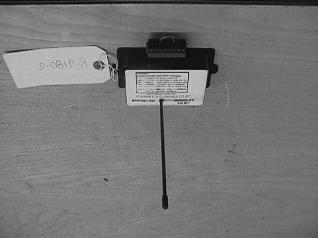
Click to zoom
Application Details
- Equipment Class
- DSC - Part 15 Security/Remote Control Transmitter
- Date of Grant
- Oct 21, 2001
- Application Purpose
- Original Equipment
- Date of Application
- Oct 21, 2001
- Equipment Note
- Remote system between a vechicle and building
- Frequency Range
- 418.00000000 - 418.00000000
- Country
- United States
Documents & Files
Document Text
Text extracted from the exhibit documents filed with the FCC. Open a document above to read the original.
Users Manual
FILE: 09-133 DATE: 05-08-00 INSTRUCTION MANUAL 418 MHZ TRANSMITTER and RECEIVER A Radio Frequency Control Link That Permits Operating Electrical Devices In A Building From A Transmitter In A Vehicle MODEL# 091-133 INPUT, RECEIVER: 120VOLTS, 50/60 Hz AC TRANSMITTER: 12 VOLTS DC OUTPUT: RELAY CONTACT CLOSURE. N.O., 2 AMPS 3 YEAR WARRANTY INTRODUCTION ANY CHANGE MADE BY THE USER TO THIS EQUIPMENT WITHOUT THE WRITTEN APPROVAL OF KUSSMAUL ELECTRONICS CO INC COULD VOID THE USERS AUTHORITY TO OPERATE THIS EQUIPMENT CAUTION: The Model 091-133 418 MHz Transmitter/Receiver is a remote control system between a vehicle and a building. It is intended to operate various electrical devices in the building when signaled to do so from the vehicle. The Transmitter is installed in the vehicle above the dash and near the windshield. The receiver is installed on a shelf or on a wall, away from large metallic surfaces. The transmitter and receiver have four proprietary channels; channels 6, 7,8, & 9. Channel 9 is dedicated to automatically producing a 1 second closed contact at the receiver channel 9 output upon the ignition switch being turned on. This is intended to actuate the Fan Controller in the building. The other three channels could be used to open the door, close the door, or stop door movement. The other three channels are operated by momentary push button switch mounted on the dashboard by the installer. Each Transmitter and Receiver can be coded using a DIP switch mounted on each unit. In this way any number of proprietary channels can be implemented. The Transmitter is of such low power that a license is not required to operate it, and it has a range of 150 feet to the receiver. For single receiver systems; each truck can have a transmitter which will communicate with the single receiver. For multiple Receiver systems each Receiver will be assigned a code. A given Transmitter will only communicate with a receiver if it has the code as that receiver. Dip switches on the Receiver and Transmitter code the Transmitter and Receiver. Thirty-two different codes are possible. INSTALLATION & WIRING Mount the transmitter on the top of the dash, facing the windshield with the antenna vertical. Mount the receiver at a convenient location in the firehouse. It may be shelf mounted on its base or wall mounted using a bracket. The antenna shall be vertical. Be sure that there are not any metallic barriers between each transmitter and the receiver. Make the connections shown in Figure 1. Figure 2 shows the mounting dimensions for each unit. SETTING THE CODE Each Transmitter and Receiver has a dip switch, the setting of which determines the code sent and received. The dip switch in the Transmitter and it’s corresponding receiver must be set to the same code The units are normally coded OFF, OFF, OFF, OFF, OFF for single Receiver systems. For multiple Receiver systems, each receiver is given a separate code. The corresponding transmitters must be set to the same code. To change the code, remove the Transmitter and Receiver top covers and change the dip switches. INSTALLATION EXAMPLES Figures 3 and 4 show possible installation examples for the Model 091-133 Transmitter and Receiver. There are many other possible installations. Consult Kussmaul Electronics Co. Inc. Engineering Dept. to discuss your particular problem. ON 123 4 5 SPECIFICATION AND OUTLINE Operating Frequency: 418 MHz Transmitter Main Input Power: 12 volts D.C. battery. Transmitter Current Draw: Less than 15 milliamperes D.C.. Number of Transmitter independent (or proprietary) Channels: 4 Number of possible Transmitter Codes: 32 Receiver Main Input Power: 115 volts, 60 Hertz Receiver AC Current Draw: 15 milliamperes AC Number of Receiver independent (or proprietary) Channels: 4 Number of Possible Receiver Codes: 32 Range of Transmission (between Transmitter & Receiver): 150 feet typical Temperature Environment: 0 to 50 deg C. Outline Drawing: Refer to Figure 2 INSTALLATION RECORD & WARRANTY Date Installed________________________________________ Installed By___________________________________________ Vehicle Identification_________________________________ Vehicle Owner________________________________________ WARRANTY All products of Kussmaul Electronics Company Inc. are warranted to be free of defects of material or workmanship. Liability is limited to repairing or replacing at our factory, without charge, any material or defects which become apparent in normal use within 3 years from the date the equipment was shipped. Equipment is to be returned, shipping charges prepaid and will be returned, after repair, shipping charges paid. Kussmaul Electronics Company, Inc. shall have no liability for damages of any kind to associated equipment arising from the installation and /or use of the Kussmaul Electronics Company, Inc. products. The purchaser, by the acceptance of the equipment, assumes all liability for any damages which may result from its installation, use or misuse, by the purchaser, his or its employees or others.
Block Diagram
7 inch, 418 MHZ, 50 Ohm Whip Antenna Open (D6)Linx Model TXM-418-LC Transmitter Module +5 VDCStop (D7) Close (D8) Fan (D(9) +12 VDC 4 Channel manual & Momentary Data Vehicle Ignition Switch Block Diagram, Kussmaul Model 091-133T 418 MHZ Transmitter Holtek Model 600 Digital Encoder with built in 83 KHZ Oscillator and 4 Channel Encoder Amplifier 418 MHZ SAW Oscillator 5 Bit Address Selector 2 Second One Shot Multi- Vibrator 7 inch, 418 MHZ, 50 Ohm Whip Antenna
External Photos
Page 1 of 1 10/22/2001file://C:\TCB%20Certifications\Retlif\Retlif%20NY\Kussmaul%20Electronics\Exhibit%...
Operational Description
Circuit Description Model 091-133T 418 Mhz Transmitter The Unit operates from the 12 volt battery of an Ambulance or Fire Truck. A schematic for this Transmitter (Drawing # 091-133-002) is attached to this description. A Block Diagram is also provided in this submission. Power Supply The 12 volts enters J1-8 and J1-7, where it is regulated and filtered to +5 volts D.C. by the U1 regulator chip. This 5 volt D.C. provides power to timer U5, Encoder U3, and the transmitter module U4. Encoder The U3 encoder is a four channel device that converts 4 parallel data bits to a serial word for transmission. The parallel data bits are entered into U3 pins 2,3,4 & 5. The data is serially transmitted with a 5 bit address such that only a receiver with a decoder having the identical address will receive the data. This address is inputted to the encoder by a five bit DIP switch (S1) via U3 pins 11,12,13,14 & 15. The serial word is sent from U3 pin 6 to the transmitter module U4 pin 2. The encoder accepts parallel data from 3 momentary push buttons at U3-pins 5,4 and 2. This data is labeled Manual Stop (D7), Manual Open (D6), and Manual Close (D8). The fourth piece of parallel data originates at the vehicle’s ignition switch. However, this is not momentary data. Timer U5 acting as a 2 second one shot multi-vibrator converts ignition switch turn on to a two second pulse which prevents continuous transmission. The output of the one-shot is labeled D9 and is routed to U3 pin 3. If parallel data is not present at D6, D7, D8, and D9, the encoder does not produce a serial word. Since the encoder serial word is digital, there is a duty cycle associated with it. In the worst case, this duty cycle was measured to be 40% maximum. This allows the allowable peak field strength to be 2.5 times the allowable average field strength. Transmitter The transmitter module is produced by LINX Technologies under their model Number TXM418LC. It contains all of the RF components except for the antenna, and is designed to meet or exceed all FCC requirements. The module contains a 418 MHz SAW (Surface Acoustic Wave) oscillator. The carrier is only present if serial data is present. Thus if D6, D7, D8 and D9 at the encoder do not have active data at their inputs, there is no serial word present, and the transmitter does not emit a carrier. The 40 % maximum duty cycle of the encoder serial data allows the peak field strength to be 2.5 times the allowable average field strength of 10,000 uVolts/ Meter (measured at a distance of 3 Meters), or 25, 000 uVolts/ Meter peak Antenna and Grounding The antenna is a 50 Ohm, 7”, ¼ wavelength whip antenna whose input is fed from the pin 5 output of the transmitter via an attenuation pad consisting of R9, R10, R11. The antenna sits above a ground plane on the PC Board. This ground plane also is ground for the transmitter, the power supply, and all other PC Board components. .
Test Report
Retlif Testing Laboratories R Test Report No. R-9180-2 FCC ID: PXFDSC091-133XMTR APPLICANT Kussmaul Electronics Co., Inc. 170 Cherry Avenue West Sayville, NY 11796 MANUFACTURER Kussmaul Electronics Co., Inc. 170 Cherry Avenue West Sayville, NY 11796 TEST SPECIFICATION:FCC Rules and Regulations Part 15, Subpart C, Para. 15.231 TEST PROCEDURE:ANSI C63.4:1992 TEST SAMPLE DESCRIPTION BRANDNAME: Kussmaul Electronics Co., Inc. MODEL: 091-133T TYPE: Pulsed Transmitter POWER REQUIREMENTS: +12 VDC derived from vehicle battery FREQUENCY OF OPERATION: 418 MHz TESTS PERFORMED Para. 15.231(b), Radiated Emissions, Fundamental and Harmonics Para. 15.231(b)(3), Radiated Emissions, Spurious Case Para. 15.231(c), Occupied Bandwidth Para. 15.35, Duty Cycle Determination REPORT OF MEASUREMENTS Applicant: Kussmaul Electronics Co., Inc. Device:Pulsed Transmitter FCC ID: PXFDSC091-133XMTR Power Requirements: +12 VDC derived from vehicle battery Applicable Rule Section:Part 15, Subpart C, Section 15.231 Retlif Testing Laboratories R Test Report No. R-9180-2 FCC ID: PXFDSC091-133XMTR Retlif Testing Laboratories R Test Report No. R-9180-2 FCC ID: PXFDSC091-133XMTR REPORT OF MEASUREMENTS (continued) TEST RESULTS 15.231 (a):This device is used as a remote control transmitter. 15.231 (a)(1) &The transmitter is manually operated and ceases transmission within 5 15.231(a)(2):seconds after deactivation. 15.231 (a)(3):The transmitter does not perform periodic transmissions. 15.231 (b):The fundamental field strength did not exceed 10330μV/M (Average) at a test distance of 3 meters. In addition, the requirements of section 15.35 for averaging pulsed emissions and for limiting peak emissions were met. The field strength of harmonic and spurious emissions did not exceed 1033 μV/M (AVERAGE). DETERMINATION OF FIELD STRENGTH LIMITS The field strength limits shown below are found in Section 15.231. Frequency Limit F1=2603750=L1 Fo=418Lo F2=47012500=L2 The formula below was utilized to determine the limits: Limit = L1 + [(Fo-F1)(L2-L1)/(F2-F1)] Solving yields: Fundamental Limit= 10330 μV/M (AVERAGE) @ 3 Meters Harmonic Limit= 1033 μV/M (AVERAGE) @ 3 Meters Retlif Testing Laboratories R Test Report No. R-9180-2 FCC ID: PXFDSC091-133XMTR REPORT OF MEASUREMENTS (continued) DUTY CYCLE DETERMINATION The unit’s RF output was directly coupled to the input of the spectrum analyzer. The analyzer was set for a frequency span of 0Hz. The sweep time was then adjusted in order to display one full pulse train. The transmitter on time was then summed and compared to the time for one full cycle in order to obtain the duty cycle. (See plots for additional information) Transmitter On Time=23.6 milliseconds (maximum- per cycle) Transmitter Cycle Time=62.85 milliseconds Transmitter Duty Cycle=37.5 % CALCULATION: 18 x 800 μs (large pulse) = 14.4 milliseconds 23 x 400 μs (small pulse)= 9.2 milliseconds 9.2 + 14.4= 23.6 milliseconds Cycle Time=62.85 milliseconds Duty Cycle =37.5 % Correction Factor = 20 log(0.375) =-8.5 SPECTRUM ANALYZER DESENSITIZATION CONSIDERATIONS Due to the nature of the emissions being measured, care was taken to ensure that the resolution bandwidth of the spectrum analyzer was adequate to provide accurate measurements. The following formula was utilized: Setting pulse desensitization equal to zero and utilizing the minimum observed pulse width of 400μs yields a minimum required bandwidth of 1.67 kHz. FCC specified bandwidths of 100kHz and 1MHz were utilized below and above 1GHz, respectively. Retlif Testing Laboratories R Test Report No. R-9180-2 FCC ID: PXFDSC091-133XMTR GENERAL NOTES 1.All readings were taken utilizing a peak detector function at a test distance of 3 meters. 2.The duty cycle was applied to the peak readings in order to determine the average value of the emissions. 3.The frequency range was scanned from 30 MHz to 4.2 GHz. All emissions not reported were more than 20 dB below the specified limit. Retlif Testing Laboratories R Test Report No. R-9180-2 FCC ID: PXFDSC091-133XMTR EQUIPMENT LIST FCC15.231 Compliance Testing ENTypeManufacturerDescriptionModel No.Cal DateDue Date 067Open Area Test SiteRetlif3 MeterRNY09/20/200009/20/2003 128CDouble Ridge GuideEaton Corporation1 GHz - 18 GHz9600109/21/200109/21/2002 133Broadband Pre-AmplifierElectro-Metrics10 kHz - 1 GHz, 26dBBPA-100006/13/200106/13/2002 141Spectrum AnalyzerHewlett Packard100 Hz - 40 GHz8566B07/02/200101/02/2002 141AGraphics PlotterHewlett PackardN/A7470A03/05/200103/05/2002 141BQuasi-Peak AdaptorHewlett Packard100 Hz - 1 GHz85650A02/20/200101/02/2002 206B6.0 dB AttenuatorTexscan0 - 1.0 GHzFP-50 - 6 dB06/13/200106/13/2002 523BiconilogElectro-Mechanics26 - 2000 MHz3142B09/28/200109/28/2002 543PreamplifierHewlett Packard1.0 GHz - 26.5 GHz8449B06/27/200106/27/2002 Retlif Testing Laboratories R Test Report No. R-9180-2 FCC ID: PXFDSC091-133XMTR FCC 15.231(b) RADIATED EMISSIONS, FUNDAMENTAL & SPURIOUS CASE See separate e-file attachment named REfundharm.pdf and REspur.pdf Retlif Testing Laboratories R Test Report No. R-9180-2 FCC ID: PXFDSC091-133XMTR FCC 15.231(c) OCCUPIED BANDWIDTH Please refer to separate electronic file named Occbw.pdf Retlif Testing Laboratories R Test Report No. R-9180-2 FCC ID: PXFDSC091-133XMTR FCC 15.35 DUTY CYCLE Please refer to separate electronic file named Dutycycle.pdf Retlif Testing Laboratories R Test Report No. R-9180-2 FCC ID: PXFDSC091-133XMTR Test Setup Photograph Retlif Testing Laboratories R Data Sheet 1 of 4 Test Method: FCC Part 15 Subpart C Radiated Emissions, Fundamental & Harmonic Emissions Customer: Kussmaul Electronics Co., Inc. Job No. R-9180-2 Test Sample: 418MHz Pulsed Transmitter Paragraph: 15.231(b) Model No.: 091-133T FCC ID: PXFDSC091-133XMTR Operating Mode: Continuously Transmitting a Pulsed 418 MHz Signal Technician: Peter Lananna Date: September 24, 2001 Notes: Test Distance: 3 Meters Detector: Peak, Unless otherwise specified Test Freq. Antenna Pol./Height EUT Orientation Meter Reading Correction Fact…
Text truncated - open the document above for the full version.
Test Setup Photos
Page 1 of 1 10/22/2001file://C:\TCB%20Certifications\Retlif\Retlif%20NY\Kussmaul%20Electronics\Exhibit%...
Contact Information
Applicant
Ernest Kussmaul(President)
Technical Contact
Retlif Testing LaboratoriesThomas Schneider
[email protected]1 631 737-1500
795 Marconi Avenue · Ronkonkoma, New York · United States
Non-Technical Contact
Retlif Testing LaboratoriesMichelle White
[email protected]1 631 737-1500
Test Firm
Retlif Testing LaboratoriesMichael Bozza
Technical Specifications
| # | Rule Parts | Frequency Range | Power Output |
|---|---|---|---|
| 1 | 15.231 | 418 MHz - 418 MHz | - |