PXQOP-42TN42" PDP Monitor
ORCOM Co., Ltd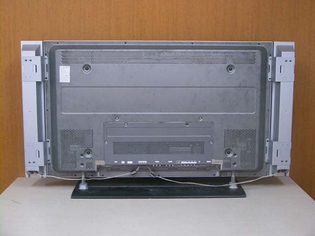
Click to zoom
Application Details
- Equipment Class
- JBP - Part 15 Class B Computing Device Peripheral
- Date of Grant
- Nov 01, 2004
- Application Purpose
- Original Equipment
- Date of Application
- Nov 01, 2004
- Equipment Note
- 42" PDP Monitor
- Company
- ORCOM Co., Ltd
- Country
- South Korea
Documents & Files
Document Text
Text extracted from the exhibit documents filed with the FCC. Open a document above to read the original.
Users Manual
PDP-TV (PLASMA DISPLAY PANEL) PDP-TV (PLASMA DISPLAY PANEL) Owner’s Instructions Before operating the unit, please read this manual thoroughly, and retain it for future reference. Model : OP-42TN1U/OP-42TN2U OP-42TN1U/42TN2U(GB) 2004.10.1 10:37 AM ̆ ` 1 mac001 1200DPI 100LPI • Do not place the PDP on an unstable cart, stand, tripod, bracket, table, or floor where it can fall. • Do not expose the PDP to extreme temperature conditions or to extreme humidity conditions. • Do not expose the PDP to direct sunlight and other sources of heat. • Do not expose the PDP to any liquids. • Never put objects of any kind into the television, and do not place a water-containing vessel on the PDP. • During a storm conditions (especially when there is lightning) unplug the PDP from the mains socket and aerial. • Do not step on or twist the power cord. • Do not overload wall outlets or extension cords as this can result in a risk of fire or electric shock. • Please use a soft and dry cloth (not containing volatile matter) when you clean the PDP. • If the PDP is broken, do not try to repair it yourself. Contact qualified service personnel. • If the remote control is not used for a long period of time, remove the batteries and store it in a cool, dry place. • Do not drop the remote control. • When installing a PDP such as for an exhibition, etc., there is risk of overheating the unit if placed irectly on a floor or carpet. Be sure to use a proper stand, wall mount, ceiling mount, or Lift-Stand offered by your dealer. (Do not use and exhibit by laying down or sitting the unit directly on the floor.) • Ventilation : The ventilation should not be impeded by covering the ventilation openings with items,such as newspapers,table-clothes,curtains,etc. Accidental contact with high voltage components could be result in electric shock. Never place the set in a confined space such as a bookcase or built-in cabinet,unless proper ventilation is provided. The set requires minimum distances around the apparatus for sufficient ventilation • Water and Moisture : Never install the set in the following places : in the bathroom,in a wet basement(Dripping or splashing water). No objects filled with liquids,such as vases,shall be placed on the apparatus. Safety Instructions Caution 2 The lightning flash and arrow head within the triangle is a warning sign alerting you of “dangerous voltage” inside the product. The exclamation point within the triangle is a warning sign alerting you of important instructions accompanying the product. NOTE: The main voltage is indicated on the rear of the PDP and the frequency is 50 or 60Hz. WARNING: TO PREVENT DAMAGE WHICH MAY RESULT IN FIRE OR SHOCK HAZARD, DO NOT EXPOSE THIS APPLIANCE TO RAIN OR MOISTURE. CAUTION: TO PREVENT ELECTRICAL SHOCK, DO NOT REMOVE REAR COVER, NO USER SERVICEABLE PARTS INSIDE. REFER SERVICING TO QUALIFIED SERVICE PERSONNEL. CAUTION RISK OF ELECTRIC SHOCK DO NOT OPEN OP-42TN1U/42TN2U(GB) 2004.10.1 10:37 AM ̆ ` 2 mac001 1200DPI 100LPI • Screen Image retention Do not display a still image (such as on a video game or when hooking up a PC to this PDP) on the plasma monitor panel for more than 2 hours as it can cause screen image retention. This image retention is also known as “screen burn”. To avoid such image retention, reduce the degree of brightness and contrast of this screen when displaying a still image. • Cell Defect The plasma display panel consists of fine cells. Although the panels are produced with more than 99.9 percent active cells, there may be some cells that do not produce light or remain lit. • Height The PDP can normally operate only under 2000m in height. It might abnormally function at a place over 2000m in height and do not install and operate there. • Warranty -Warranty does not cover any damage caused by image retention. - Burn-in is not covered by the warranty. User Instructions Checking Parts 3 Owner ’s Instructions Remote Control/AAA BatteriesPower CORD OP-42TN1U/42TN2U(GB) 2004.10.1 10:37 AM ̆ ` 3 mac001 1200DPI 100LPI • FOREWORD Safety Instructions......................................................................................................2 Caution ......................................................................................................................2 User Instructions................................................................................ ........................3 • CONNECTING AND PREPARING YOUR DISPLAY Your New Plasma Display Panel.................................................................................6 Infrared Remote Control.............................................................................................8 Inserting the Batteries in the Remote Control ............................................................9 Connecting to an Aerial or Cable Television Network ...............................................10 Connecting a Satellite Receiver or Decoder ................................................................10 Switching On and Off .................................................................................................11 Placing in Standby Mode............................................................................................11 Choosing Your Language ...........................................................................................12 Viewing an External Signal Source ............................................................................12 • SETTING THE CHANNELS Storing Channels Automatically .................................................................................13 Storing Channels Manually ........................................................................................14 • USING YOUR DISPLAY Using the Fine Tune ...................................................................................................15 Changing the Picture Standard...................................................................................16 Freezing …
Text truncated - open the document above for the full version.
Block Diagram
U19 FLASH_8M I1 AD9883A U18 U15 PW1231 U17 SDRAM U14 SAA7118 U13 SIL1161 PDP 42" PDP TV &MONITOR Block Local PW181 DVI AUDIO IN RGB AV2 AV1 S-VIDEO COMPONENT AC_IN TUNER SPEAKER OUT_PUT RX- GRE[7:0]/GGE[7:0]/GBE[ 7:0] MSP3420G I1 PC_DVI_R/L LA4282 VGA_R/G/B SPK_R AV1_IN_R/L AV_CVBS1 S-VIDEO_C/Y DTV_Y_Pb_Pr TUNER_CVBS_M U1 Z86229 TTX_CVBS AV_RGB_TTX_R/G/B/FB VY[0..7]/VUV[0..7] VR[7:0]/VG[7:0]/VB[ 7:0] 31RAMA[13:0] A[19:1]/D[15:0] PANEL Keys Disgram AC_100V~240V 50/60Hz 12VSC ACD RLYON STBY VSON 5VD 5VSC AV_CVBS2 U23 DS90C383A DRE[7:0]/DGE[7:0]/DBE[ 7:0] TTX0,1,2,3/CLK DVD/DTV/S_VIDEO_R/L SIF1 AMP_R AMP_L SPK_L PI5V330 I10 DVD_Y_Cb_Cr OUT_R/G/B DVD/DTV/S_VIDEO_R/L VGA_HSYNC/VSYNC GRO[7:0]/GGO[7:0]/GBO[ 7:0] 31RAMD[13:0] SCL2SDA2 SCLSDA GSCLGSDA GSCL GSDA U1 24LC21A SCLSDA SDASCLSCL2SDA2 24LC32A SCL U20 SDA SDA2 SCL2 SDA2SCL2 SDA2SCL2 AV2_IN_R/L I2 (SUB) (SUB) (SUB) 35Mhz
ID Label/Location Info
ID Label Sample Location Information
Test Report
IST Co., Ltd EMC LABORATORY TEST REPORT NO. : 04-IST-0314 1 of 15 Certification of Compliance CFR 47 Part 15 Subpart B Test Report File No. : 04-IST-0314 Date of Issue : November 2, 2004 Model(s) : OP-42TN Kind of Product : 42” Plasma Display Panel Applicant : Orcom CO.,LTD Address : 1113-1 Dalan-Dong, Dongan-Gu, Anyang-Si, Kyonggi-Do, Korea Manufacturer : Orcom CO.,LTD Address : 1113-1 Dalan-Dong, Dongan-Gu, Anyang-Si, Kyonggi-Do, Korea Test Result ■ Positive □ Negative Reviewed By Approved By Comment(s) - Investigations requested : Measurement to the relevant clauses of FCC rules and regulations Part 15 Subpart B – Unintentional Radiators, Class B. - The test report with appendix consists of 15 pages. - The test result only responds to the tested sample. - It is not allowed to copy this report even partly without the allowance of IST EMC Laboratory. - This equipment as for has been shown to be capable of continued compliance with the applicable technical standards as indicated in the measurement report and was tested in accordance with the measurement procedures specified in ANSI C63.4 2001. J. H. Lee / EMC Group Manager G. Chung / Chief IST Co., Ltd EMC LABORATORY TEST REPORT NO. : 04-IST-0314 2 of 15 TABLE OF CONTENTS Table of contents 2 Information of test laboratory, Environmental conditions, Power used, Product information 3 Descriptions of test Conducted Emission 4 Radiated Emission 5 Equipment Under Test 6 Summary 7 ■ Test Conditions and Data - Emissions ◆ Conducted Emissions 0.15MHz - 30MHz Applicable Test Conditions / Data and Plots 8-10 ◆ Radiated Emissions 30MHz - 1GHz Applicable Test Conditions / Data and Plots 11-12 Appendix A. The Photos of Test Setup 13-14 B. The Photos of Equipment Under Test 15 Note : IST Co., Ltd EMC LABORATORY TEST REPORT NO. : 04-IST-0314 3 of 15 INFORMATIONS OF TEST LABORATORY EMC LABORATORY of IST Co., Ltd. (FCC Filing Lab.) San 21-8, Goan-Ri, Baekam-Myun, Yongin-City Kyonggi-Do, 449-860, Korea TEL : +82 31 333 4093 FAX : +82 31 333 4094 ENVIRONMENTAL CONDITIONS Temperature 20.0 °C Humidity 49 % Atmospheric pressure 1008 mbar POWER SUPPLY SYSTEM USED Power supply system AC 120Vac, 60Hz (Refer to the product information) PRODUCT INFORMATION Power Source AC 100-240 V, 50/60Hz Power Consumption 300W Screen Size 42” Number of Pixels 852(H)x480(V) Pixel Pitch 1.080mm(H)x1.080mm(V) Input Terminal DVI, RGB, Audio L/R, S-Video, Component, Antenna Output Terminal Speaker Dimension 1028mm x 625mm x 89.8mm (without stand) 1028mm x 692.5mm x 270mm (with stand) Weight 35Kg (without stand) 40.5Kg (with stand) - EMC suppression device is not used during the test . - Please refer to user’s manual. IST Co., Ltd EMC LABORATORY TEST REPORT NO. : 04-IST-0314 4 of 15 < Concept Drawing > 215 >150 >40 80 Receiver DUT LISN 80 ≥ 80 80 40 ≥ 80 Measuring apparatus Mains Filter Mains Front side Equipment under test Coaxial cable Artificial mains networ k Screened room Non-metallic support 80 DESCRIPTIONS OF TEST Conducted Emissions: The measurement were performed over the frequency range of 0.15MHz to 30MHz using a 50 Ω /50uH LISN as the input transducer to a Spectrum Analyzer or a Field Intensity Meter. The measurements were made with the detector set for "Peak" amplitude within a bandwidth of 10KHz or for "quasi-peak" & “Average” within a bandwidth of 9KHz. - Procedure of Test The line-conducted facility is located inside a shielded room No.1. A 1m X 1.5m wooden table 80cm height is placed 40cm away from the vertical wall and 1.5m away from the other wall of the shielded room. The R/S ESH3-Z5 and EMCO 3825/2 LISN are bonded to bottom of the shielded room. The EUT is located on the wooden table with distance more than 80cm from the LISN and powered from the EMCO LISN .The peripheral equipment is powered from the other LISN. Power to the LISNs are filtered by a noise cut power line filters. All electrical cables are shielded by braided tinned steel tubing with inner φ 1.2cm. If the EUT is a DC-powered device, power will be derived from the source power supply it normally will be powered from and this supply lines will be connected to the EMCO LISN. All interconnecting cables more than 1m were shortened by non-inductive bundling to a 1m length. Sufficient time for the EUT, support equipment, and test equipment was allowed in order for them to warm up to their normal operating conditions. The RF output of the LISN was connected to the R/S receiver to determine the frequency producing the maximum emission from the EUT. The frequency producing the maximum level was reexamined using Quasi-Peak mode by manual measurement, after scanned by automatic Peak mode for frequency range from 0.15 to 30MHz. The bandwidth of the receiver was set to 10kHz. The EUT, peripheral equipment, and interconnecting cables were arranged and manipulated to maximize each EME emission. < Side View > IST Co., Ltd EMC LABORATORY TEST REPORT NO. : 04-IST-0314 5 of 15 DESCRIPTION OF TEST Radiated Emissions: The measurement was performed over the frequency range of 30MHz to 1GHz using antenna as the input transducer to a Spectrum analyzer or a Field Intensity Meter. The measurement was made with the detector set for "quasi-peak" within a bandwidth of 120KHz. - Procedure of Test Preliminary measurements were made at 3 meter using bi-conical and log-periodic antennas, and spectrum analyzer to determine the frequency producing the max. emission in anechoic chamber. Appropriate precaution was taken to ensure that all emission from the EUT were maximized and investigated. The system configuration, mode of operation, turn-table azimuth and height with respect to the antenna were noted for each frequency found. The spectrum was scanned from 30MHz to 300MHz using S/B bi-conical antenna and 300 to 1000MHz using S/B log-periodic antenna. Above 1GHz, linearly polarized double ridge horn antennas were used. Final measurements were made at open site with 3-meters test distance using S/B bi-log antenna or horn antenna. The …
Text truncated - open the document above for the full version.
Contact Information
Applicant
Man-Ho Kim(Manager)
Test Firm
IST Co., Ltd.C. W Kim
Technical Specifications
| # | Rule Parts | Frequency Range | Power Output |
|---|---|---|---|
| 1 | 15B | - | - |
Other Applications from ORCOM Co., Ltd
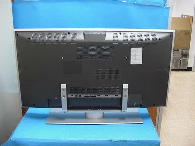
PXQOL-32T
Jun 01, 200532" LCD TV
Equipment Class
JBP - Part 15 Class B Computing Device Peripheral
PXQOP-42M1A
Sep 14, 2003PDP Monitor
Equipment Class
JBP - Part 15 Class B Computing Device Peripheral