PXWHL500MLCD Monitor
Wooyoung Telecom Co., Ltd.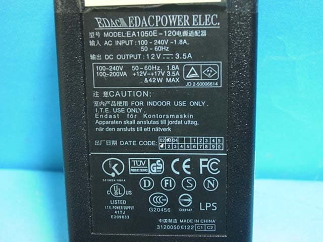
Click to zoom
Application Details
- Equipment Class
- JBP - Part 15 Class B Computing Device Peripheral
- Date of Grant
- May 29, 2003
- Application Purpose
- Original Equipment
- Date of Application
- May 29, 2003
- Equipment Note
- LCD Monitor
- Company
- Wooyoung Telecom Co., Ltd.
- Country
- South Korea
Documents & Files
Document Text
Text extracted from the exhibit documents filed with the FCC. Open a document above to read the original.
Users Manual
WOO YOUNG Telecom CO.,LTD. Users Manual FCC STATEMENT This equipment has been tested and found to comply with the limits for a Class B digital device pursuant to part 15 of the FCC Rules. These limits are designed to provide reasonable protection against harmful interference in a residential installation. This equipment generates, uses and can radiate radio frequency energy and, if not installed and used in accordance with the instructions, may cause harmful interference to radio communications. However, there is no guarantee that interference will not occur in a particular installation. If this equipment does cause harmful interference to radio or tele- vision reception, with can be determined by turning the equipment off and on, the user is encouraged to try to correct the interference by one more of the following measures: - Reorient or relocate the receiving antenna. - Increase the separation between the equipment and receiver. - Connect the equipment into an outlet on a circuit different from that to which the receiver is connected. - Consult the dealer or an experienced radio/TV technician for help. - Only shielded interface cable should be used. Finally, any changes or modifications to the equipment by the user not expressly approved by the grantee or manufacturer could void the users authority to operate such equipment. 1 Contents 1. Before Setting up 3 Brief Specification of LCD Monitor 3 Precautions 4 Instruetion for Cleaning the Monitor 7 2. Items 8 3. Setting up the LCD monitor 10 Where is a good place to position the monitor? 10 How to connect the power cord and the several cables to the LCD monitor. 11 Connecting Your LCD Monitor 12 Plug & Play 13 Warm-up Time 13 4. Adjusting The Monitor 14 The Function Control Buttons 14 How to use the Hot Key. 14 Main OSD Menu 16 COLOR 17 USER COLOR 17 OSD FUNCTION 18 VIDEO 19 Color 20 2 TV 21 Channel 21 5. Appendix 22 Appendix A. Display Modes 22 Appendix B. 15-pin D-Sub Connector 23 DPMS Power Saving Mode 24 6. Troubleshooting 25 3 Before setting up 1 Resolution : 15.0 inch XGA (1024 X 768@75Hz) Color display : 16,777,216 colors DPMS (Display Power Management Signaling) OSD (On Screen Display) Auto Configuration : Hot key DDC 1/2B : Plug & Play This is 15.0 inch TFT-LCD monitor. Before setting up the LCD Monitor, please read this manual to help your understanding of the LCD Monitor. Brief Specification of LCD Monitor According to PC system, DDC 1/2B may not be supported. If you meet Error message,check your video card which compatibility with DDC. If you eant to know more information, please contact our service center. Notice 4 Precautions If you hear a noise or smell smoke from the computer or adaptor, unplug the power cord immediately, and call the service center. There is the risk of electric shock or fire. Do not overload an electrical outlet with too many devices. There is the risk of fire. Do not unplug from the outlet by pulling the power cord or when your hands are wet. There is the risk of electric shock and fire. Do not use a damaged power cord or plug. Make sure the plug fits snugly into the outlet. There is the risk of electric shock or fire. AC outlet Power cord Do not bend the power cord excessively or place heavy objects on it. Keep children and pets away from the power cord as they may damage the power cord. There is the risk of electric shock and fire. Warning The following information will help you avoid the risk of electric shock, serious injury, and death. Plug the power cord into a properly grounded outlet. There is the risk of electric shock. 5 Do not expose the monitor to the direct sun light. Do not block the fan louvers. There is the risk of fire or damage to the monitor. Keep the monitor away from high tem- perature, humidity, and dust. Operating environmentdegrees Celsius Operating environment Do not allow any object or liquid to enter inside the monitor. There is the risk of electric shock, fire, or damage to the monitor. 6 Do not clean the LCD with abrasive chemicals. There is the risk of damage to the LCD. Use a proper voltage/current level indi- cated Do not scratch and damage the LCD with sharp objects. Keep the monitor away from objects and electrical appliances that may gen- erate electromagnetic fields. Place the monitor on a flat, stable sur- face. The monitor may fall and there is the risk of damage or injury Unplug the power cord when the moni- tor is not in use for a prolonged period of time. Caution The following information will help you avoid the risk of minor or moderate injury, or damage to the monitor. 7 Instruction for Cleaning the Monitor Make sure the power cord is unplugged. Do not spill or pour liquid on the monitor. Cleaning the LCD panel 1 .Use a clean, soft cloth to wipe off dust from the LCD. 2 .If still not clean, wipe the LCD with a clean soft cloth with a small amount of glass cleaner? without alcohol or ammonia. Cleaning other parts of the monitor 1 .Use a clean, soft cloth to wipe off dust from the monitor. 2 .If still not clean, wipe the LCD with a clean soft cloth with a small amount of glass cleaner? without alcohol or ammonia. Caution Do not use alcohol or ammonia based cleaning products. Abrasive chemicals, such as alcohol or ammonia, may damage the monitor. The company is not responsible for the damages to the monitor caused by the use of alcohol or ammonia based cleaning prod- ucts. 8 Items 2 LCD Monitor DC Adapter 15-pin D-Sub Signal Cable User Manual 9 Please make sure the following items are included with your monitor. If any items are missing, contact your dealer. Notice RCA Cable Audio Cable S-Video Cable External TV Box 1 0 Setting up the LCD monitor 3 Place the LCD monitor on a solid and flat surface. If dropped, the screen can be dam- aged easily. Where is a good place to position the monitor? 1 1 How to connect the power cord and the several cables to the LCD monitor. No. 1 2 PC AUDIONIN Speaker Cable External Speaker Cable SPK OUT NameCable connections 3 4 DC12V…
Text truncated - open the document above for the full version.
Block Diagram
LCD CONNECTOR Inverter14.31818MHz Connector VIDEO SIGINAL 12.000MHz MICRO CONTROLLER SOUND SIGINAL Key J402 Connector S- VIDEO TUNER INPUT LCD MODULE AUDIO L HL500M BLOCK DIAGRAM INVERTER SCALAR X-TAL AUDIO R 12V ADAPTERVIDEO X-TAL ADC DC JACK D-SUB SAA7114 24.576MHz VIDEO
ID Label/Location Info
ID Label Sample & Location Information
Test Report
File No. 03-IST-081/FB IST EMC LAB. 1 17 IST EMC Lab. San 21-8 Goan-Ri, Baekam-Myun, Yongin-Si, Kyunggi-Do, KOREA International - Tel : 82-31 - 333 - 4093. Fax : 82-31 - 333 - 4094. Domestic - Tel : 031 - 333 - 4093. Fax : 031 - 333 - 4094. IST EMC LAB. EMISSION TEST REPORT Test report file No. : 03-IST-081/FB Date of issue : Apr. 04, 2003 Model / Type No. : HL500M Basic Alternate Kind of product Brand name Applicant Manufacturer License holder Address : 15” LCD Monitor : WOOYOUNG : WOO YOUNG Telecom CO.,LTD. : WOO YOUNG Telecom CO.,LTD. : WOO YOUNG Telecom CO.,LTD. : 222-1, Suwolam-Ri, Seotan-Myum, Pyungtaek-City, Kyunggi-Do, 451-852, Korea Test result according to the regulation(s) Positive Negative at page 3. This test report with appendix consists of 17 pages. The test result only responds to the tested sample. It is not allowed to copy this report even partly without the allowance of the Test Laboratory. This equipment is complied with the applicable technical standards as indicated in the measurement report and was tested in accordance with the measurement procedures specified in ANSI C63.4-1992. File No. 03-IST-081/FB IST EMC LAB. 2 17 IST EMC Lab. San 21-8 Goan-Ri, Baekam-Myun, Yongin-Si, Kyunggi-Do, KOREA International - Tel : 82-31 - 333 - 4093. Fax : 82-31 - 333 - 4094. Domestic - Tel : 031 - 333 - 4093. Fax : 031 - 333 - 4094. DIRECTORY A) Documentation. Page Directory Test regulations Information of Test Regulation Equipment under Test Test Conditions Test Result Measurement Uncertainty Test-setup Summary 2 3 3 4 5 ~ 6 7 8 9 ~ 11 17 B) Test Data. Conducted emissions (Mains) Radiated emissions : 150 kHz - 30 MHz : 30 MHz – 1 GHz 12 ~ 14 15 ~ 16 C) Appendix File No. 03-IST-081/FB IST EMC LAB. 3 17 IST EMC Lab. San 21-8 Goan-Ri, Baekam-Myun, Yongin-Si, Kyunggi-Do, KOREA International - Tel : 82-31 - 333 - 4093. Fax : 82-31 - 333 - 4094. Domestic - Tel : 031 - 333 - 4093. Fax : 031 - 333 - 4094. TEST REGULATIONS The tests were performed according to the following regulations ; - FCC Part 15, Subpart B (Unintentional Radiators, Class B) Information of Test Laboratory IST EMC Lab. San 21-8 Goan-Ri, Baekam-Myun, Yongin-Si, Kyunggi-Do, Korea International - Tel : 82-31 - 333 - 4093. Fax : 82-31 - 333 - 4094. Domestic - Tel : 031 - 333 - 4093. Fax : 031 - 333 - 4094. EQUIPMENT UNDER TEST Equipment Description : LCD Pannel : - Type : HSD150XX49 (HANNSTAR) - Size : 15inch (304.1mm x 228.1mm) Resolution : - 1024 x 768, 75 Hz Dimensions : - 435(W) x 425(H) x 241(D) mm Power Source : - DC 12 V, 3.5 A Power Consumption : - 42 W (Max) Power Supply Adapter : - Model : EA1050E-120 - Maker : EDAC POWER ELEC. - Input : 100 ~ 240 Vac, 1.8 A, 50/60 Hz - Output : 12 Vdc, 3.5 A File No. 03-IST-081/FB IST EMC LAB. 4 17 IST EMC Lab. San 21-8 Goan-Ri, Baekam-Myun, Yongin-Si, Kyunggi-Do, KOREA International - Tel : 82-31 - 333 - 4093. Fax : 82-31 - 333 - 4094. Domestic - Tel : 031 - 333 - 4093. Fax : 031 - 333 - 4094. EQUIPMENT UNDER TEST EUT Type : Table-Top. Floor-Standing. Table-Top and Floor-Standing(Combination). Operation – mode of the E.U.T. : The equipment under test was operated during the measurement under following conditions : Standby. Operational Condition : Scrolling “H” characters under MS Windows, at test mode of 1024 X 768, 75 Hz Configuration of the equipment under test : Following peripheral devices and interface cables were connected during the measurement : Equipment Type Brand Serial No. PC Vectra VL420MT HP SG23101784 Keyboard SK-2502C HP M020321066 PS/2 Mouse M-S48a HP LZC20602926 Serial Mouse M-S428 Logitech LCA53305547 Printer A0302384 Northern Telecom 26633S60168 Tuner TAPC-H701F LG Innotek Unknown Connecting Interface Cables : - Unshielded AC power cable : 1.8 m - Unshielded DC power cable (with one ferrite core) : 1.7 m - Shielded monitor’s signal cable (with two ferrite core) : 1.5 m - Unshielded RCA cable : 1.8 m (75 ohm termination) - Unshielded speaker’s cable (connected to PC) : 1.0 m - Unshielded S-Video Cable : 1.5 m (75 ohm termination) - Shielded printer’s signal cable (with two ferrite core) : 1.8 m File No. 03-IST-081/FB IST EMC LAB. 5 17 IST EMC Lab. San 21-8 Goan-Ri, Baekam-Myun, Yongin-Si, Kyunggi-Do, KOREA International - Tel : 82-31 - 333 - 4093. Fax : 82-31 - 333 - 4094. Domestic - Tel : 031 - 333 - 4093. Fax : 031 - 333 - 4094. TEST CONDITIONS The measurement of the conducted emissions (Interference voltage) was performed in a shielded room. Test location : Shielded room. No.1 Compact chamber 2 Used testing instruments : Name Type Manufacturer Calibration. Date Serial Number ESH 3 Test Receiver Rohde & Schwarz Jul. 25, 2002 892108/018 3725/2 LISN EMCO Aug. 22, 2002 9101-2068 KNW-407 LISN Hyup-Rip Aug. 21, 2002 8-883-10 ESH 3-Z2 Pulse Limiter Rohde & Schwarz Jul. 25, 2002 357.8810.52 Test - accessories : Type Manufacturer Aneroid Barometer Sato Hygrometer Sato Measurement Procedures : Conducted emissions measurments were made in accordance with ANSI C-63.4-1992, “Method of Measurement of Radio-Noise Emissions from Low-Voltage Electrical and Electronic Equipment in the Range of 9 kHz to 40 GHz”. The measurement were performed over the frequency range of 0.15MHz to 30MHz using a 50 ? /50uH LISN as the input transducer to an EMI/Field Intensity Meter. The measurements were made with the detector set for “Peak” amplitude within an IF bandwidth of 10kHz or for “quasi-peak” within a bandwidth of 9kHz. All used test-instruments as well as the test-accessories are calibrated regularly. File No. 03-IST-081/FB IST EMC LAB. 6 17 IST EMC Lab. San 21-8 Goan-Ri, Baekam-Myun, Yongin-Si, Kyunggi-Do, KOREA International - Tel : 82-31 - 333 - 4093. Fax : 82-31 - 333 - 4094. Domestic - Tel : 031 - 333 - 4093. Fax : 031 - 333 - 4094. The measurement of the radiated emissions (Electric field) in the frequency range from 30 MHz to 1GHz was performed in horizontal and vertical antenna polarization at a open-site which meet the site attenuation requirement of ANSI C63.4-1992 and a…
Text truncated - open the document above for the full version.
Contact Information
Applicant
Yu-Ho Choi(General Manager)
Test Firm
IST Co., LtdBong Kyoon Bae
Technical Specifications
| # | Rule Parts | Frequency Range | Power Output |
|---|---|---|---|
| 1 | 15B | - | - |
Other Applications from Wooyoung Telecom Co., Ltd.

PXWU70A
Jul 26, 2007LCD Monitor
Equipment Class
JBP - Part 15 Class B Computing Device Peripheral
PXWU90A
Jul 26, 2007LCD Monitor
Equipment Class
JBP - Part 15 Class B Computing Device Peripheral
PXWU90P
Jul 23, 2007LCD MONITOR
Equipment Class
JBP - Part 15 Class B Computing Device Peripheral
PXWU70D
Apr 29, 2007LCD MONITOR
Equipment Class
JBP - Part 15 Class B Computing Device Peripheral
PXWU90D
Apr 01, 2007LCD Monitor
Equipment Class
JBP - Part 15 Class B Computing Device Peripheral