PY8ELS999Keylock Cylinder
DOM Sicherheitstechnik GmbH & Co. KG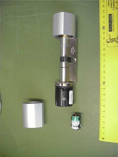
Click to zoom
Application Details
- Equipment Class
- DCD - Part 15 Low Power Transmitter Below 1705 kHz
- Date of Grant
- May 14, 2002
- Application Purpose
- Original Equipment
- Date of Application
- May 14, 2002
- Equipment Note
- Keylock Cylinder
- Frequency Range
- 0.12500000 - 0.12500000
- Country
- Germany
Documents & Files
Document Text
Text extracted from the exhibit documents filed with the FCC. Open a document above to read the original.
Users Manual
Commissioning and Programming of On-Line cylinder with Master- und Programming Card Attention: When programming cylinders external the door please make sure that the locking nose is blocked when activating the cylinder. Before programming, the cylinder must know its system membership. This procedure is unique and once in a lifetime of the cylinder and is not reversable. 1. Creating the system membership: You require: + ✔ Turn the outer knob ! !! !. You woke up the cylinder. The cylinder expects your input. ✔ Show the Master Card to the outer knob. Cylinder accepts Master Card " "" " " "" ". 2. Communication between On-Line cylinder and ELS interface ✔ To start the communication between cylionder and ELS interface both units need to know each other. The interface must be linked to the networkbecause powersupply is delivered form the network. The busmaster equivalently connected to the mains. Sequence: ! !! ! " "" " wait 3 secs." "" " wait 5 secs. " "" " " "" " The last beep is significantly longer than the one before. Due to runtimes within the system the procedure may be done 2-3 times until the last beep is significantly longer. 3. Creation of Programming Cards: You require: + + ✔ Turn the outer knob ! !! !. You woke up the cylinder. The cylinder expects your input. ✔ Show the master card to the outer knob. Cylinder accepted Master card " "" ". Wait 3 secs. " "" ". The cylinder expects your input. ✔ Show Programming card to the outer knob " "" ". Programming card was excepted. ✔ If using two or three Programming cards, show each card sequentially to the outer knob. Each card will be confirmed by a " "" ". ✔ Wait 5 secs. " "" " " "" ". Procedure completed. Cylinder has stored your Programming Cards. 4. Programmation of locking media with Programming Card You require: + + ✔ Turn the outer knob ! !! !. You woke up the cylinder. The cylinder expects your input. ✔ Show the Programming card to the outer knob. Cylinder accepted Programming card " "" " wait 3 secs. " "" ". The cylinder expects your input. ✔ Show first media to the outer knob. " "" " Locking medium was accepted. ✔ Show all media which should be stored in the cylinder sequentially to the outer knob. Each medium will be confirmed by " "" ". Cylinder accepted input of locking media. ✔ Wait 5 secs. " "" " " "" ". Procedure completed. Cylinder has stored the locking media. Attention : Instead of using the Programming Card, the Master card can also be used. 5. Deletion of locking media when available: Attention: Are the locking media no longer available you have to use the Handterminal (option) You require: + + ✔ Turn the outer knob ! !! !. You woke up the cylinder. The cylinder expects your input. ✔ Show the Programming card to the outer knob. Cylinder accepted Programming card " "" " wait 3 secs. " "" ". The cylinder expects your input. ✔ Show the Programming card for a second time to the outer knob. Cylinder accepted Programming card " "" ". Wait 3 secs. " "" ". The cylinder expects your input. ✔ Show the locking media prepared for deletion to the outer knob. " "" " The locking medium was accepted. ✔ Show all locking media which should be deleted sequentially to the outer knob. Each medium will be confirmed with a " "" ". ✔ Wait 5 secs. " "" " " "" ". Procedure completed. The cylinder has accepted the deletion of the locking media. 6. Deleting all locking media: You require: + ✔ Turn the outer knob ! !! !. You woke up the cylinder. The cylinder expects your input. ✔ Show the Programming card to the outer knob. Cylinder accepted Programming card " "" " wait 3 secs. " "" ". The cylinder expects your input. ✔ Show the Programming card for a second time to the outer knob. Cylinder accepted Programming card " "" ". Wait 3 secs. " "" ". The cylinder expects your input. ✔ Show the Programming card for a third time to the outer knob " "" " " "" ". All locking media have been deleted 7. Deletion of all Locking media and Programming Cards You require: + ✔ Turn the outer knob ! !! !. You woke up the cylinder. The cylinder expects your input. ✔ Show the Master card to the outer knob. Cylinder accepted Master Card " "" " wait 3 secs. " "" ". The cylinder expects your input. ✔ Show the Master Card a second time to the outer knob. Cylinder accepted Master Card " "" " wait 3 secs. " "" ". The cylinder expects your input. ✔ Show the Master Card a third time to the outer knob. Cylinder accepted Master Card " "" " " "" ". All Programming Cards and Locking media have been deleted. Cylinder knows only the Master Card. 8. Deleting of individual Programming Cards: You require: + + ✔ Turn the outer knob ! !! !. You woke up the cylinder. The cylinder expects your input. ✔ Show the Master card to the outer knob. Cylinder accepted Master Card " "" " wait 3 secs. " "" ". The cylinder expects your input. ✔ Show the Master card a second time to the outer knob. Cylinder accepted Master Card " "" " wait 3 secs. " "" ". The cylinder expects your input. ✔ Show for deletion prepared Programming cards to the outer knob. " "" " Programming card accepted ✔ Show maximum three Programming Cards to the outer knob. Each input will be confirmed by a " "" " . ✔ Wait 5 sec. " "" " " "" ". Procedure completed. Cylinder has deleted all Programming Cards. Quick reference for commissioning and programming of Off-Line cylinder with Master- and Programming Card Creation system membership: ! !! ! " "" " " "" " Creation of communication between cylinder and interface ! !! ! " "" " 3 sec. " "" " 5 sec. " "" " " "" " last beep significantly cantly longe Creation of Programming Cards: ! !! ! " "" " 3 sec. " "" " 5 sec. " "" " " "" " Creation of Locking Media with Programming Card: ! !! ! " "" " 3 sec. " "" " 5 sec. " "" " " "" " Deletion of individual Locking media: ! !! ! " "" " 3 sec. " "" " " "" " 3 sec." "" " ́ 5 sec." "" " " "" " Deletion of all Locking media: ! !! ! " "" " 3 sec. " "" " " "" " 3 sec. " "" " " "" " " "" " Deletion of individual Programming Cards: ! !! ! " "" " 3 se…
Text truncated - open the document above for the full version.
Cover Letter(s)
M. Becken Projekt DOM/ ELS Functional Description of the Reader Group 1 Reader group: Similarities and differences The "reader" product group consists of 3 products: 1. Armature reader "ELS-L-BE" for installation in a door armature. 2. Wall reader "ELS-L-W1" for mounting on a wall. The reader is mounted on a flush box. 3. Flush box reader "ELS-L-UP" for mounting in a flush box. All 3 readers have the following features in common: • Functionality • Hardware for processor, transmitter electronics, power supply and EMC-relevant components • Printed circuit board for the above-mentioned hardware • Firmware They differ in the following points: • Size of antenna • Design of the assembly printed circuit board. This assembly printed circuit board is used for adapting fixings and connectors to the individual applications. Variants: • ELS-L-BE armature reader: Connection through soldered on cable. Antenna construction requirement: see Appendix • ELS-L-W1 wall reader: Connection through wall transmitter printed circuit board (1030041). Antenna construction requirement: see Appendix • ELS-L-UP flush socket reader: Connection through flush reader printed circuit board (1030042). Antenna construction requirement: see Appendix. The following diagram gives an overview of these connections within the "reader" product group: M. Becken Projekt DOM/ ELS Beschlagleser 2030040 Platine Beschlagleser 1030040 Montagesatz Beschlagleser 1030090 Wandleser 2030041 Platine Beschlagleser 1030040 Platine Wandleser 1030041 Montagesatz Wandleser 1030091 UP-Leser 2030042 Platine Beschlagleser 1030040 Platine UP-Leser 1030042 Montagesatz UP-Leser 1030092 M. Becken 25.11.98 Datei: Leser.cht Overview of reader group M. Becken 25.11.98 File: Leser.cht Armature reader M. Becken Projekt DOM/ ELS Armature reader board Armature reader mounting set Wall reader Armature reader board Wall reader board Wall reader mounting set Flush reader Armature reader board Flush reader board Flush reader mounting set 2 Common components The components common to all of the products in the reader group are: • Functionality • Hardware for processor, transmitter electronics, interface, power supply and EMC-relevant components • Printed circuit board for the above-mentioned hardware • Firmware 2.1 Functionality The task of the products within the reader group is to provide an interface between host devices and transponders (=contactless identification units). For this purpose, the serial numbers of transponders of the types • Philips Hitag 1 • Philips Hitag 2 • Deister are read in and made available to the host computer via an interface. Via an input (control circuit), the host computer can give the reader instructions for controlling optical (LED) and acoustic (buzzers) display elements, as well as controlling communication with the transponders. Melde = Signal HOST Reader Transponder M. Becken Projekt DOM/ ELS 2.2 Hardware The reader group hardware includes the following components: • Power supply • EMC protective wiring • Processor with periphery and security coprocessor (PhilipsHTRC120) for communication with transponders Hitag 1 and Hitag 2. • Reader electronics around read-integrated switching circuit (Philips HTRC 110) • Interface with host The details can be found in the attached wiring diagrams. The levels of the 5 connection wires are: +12V 12V to earth GND Operating earth Signal Rest level: 12V Active: 0V D0, D1 Rest level: 0V Active: 12V The two carrier boards • Wall reader board (1030041) and • Flush reader board (1030042) support the following components: • LED for display of operational readiness • Buzzer as acoustic display element • Terminals for connecting the device • Connections for the antenna 2.3 Firmware The firmware is identical for all products in the reader group. It enables the reader to be operated on two different host computers. The characteristics of these two connections are explained in Chap. 3. The firmware is permanently programmed into the processor and must not be modified. Internal processing data are stored exclusively in the processor’s own RAM. Function-relevant data do not exist. Error status are monitored by the following: • Reset generator monitors the operating voltage and triggers a reset if the operating voltage falls below the reset threshold of 4.5V. • A watchdog monitors the program sequence. If unforeseen conditions arise within the processor, a reset is triggered within a maximum of 140ms. M. Becken Projekt DOM/ ELS As the reader immediately resumes its operation after a reset, no functional failure occurs in the event of a reset status. 3 Operating modes The reader has two operating modes: 1. Reader mode 2. ELS mode The modes are explained below: 3.1 Reader mode Mode activation: Switch on the device Function: • Reading out the serial number of a recognised transponder. • Output of the read serial number from D1 and D0 in Wiegand format. • Monitoring of the signal input for static conditions and control of the LEDs and the buzzer. • Monitoring of the signal input for known protocols, which activate ELS mode. 3.2 ELS mode Mode activation: Receipt of a commutation protocol at the signal input Function: • Reading out the serial number of a recognised transponder. • Output of the read serial number from D1. Own protocol is used. • Monitoring of the signal input for protocols for controlling the LEDs and the buzzer. • Monitoring of the signal input for known protocols for communication with a transponder 4 Displays 2 light diodes and an acoustic signal transmitter are available for user information. The yellow LED on the wall reader is not controlled by the electronics. In the Pentagon and ELS modes, the display elements take on the following status: M. Becken Projekt DOM/ ELS Pentagon mode: The reader principally recognises the status, which it is to display, by the status of the signal input. Status Signal input interface definition Red LED Green LED Acoustic display Ready for operation Rest status on …
Text truncated - open the document above for the full version.
External Photos
CETECOM ICT Services GmbH Test report no.: 3_2801-B/01Issue Date: 16.05.2001Page 16 (19) PHOTOGRAPHS OF THE EQUIPMENT Key lock ELS 999 Photograph no.: 3 CETECOM ICT Services GmbH Test report no.: 3_2801-B/01Issue Date: 16.05.2001Page 17 (19) PHOTOGRAPHS OF THE EQUIPMENT Key lock ELS 999 Photograph no.: 4
ID Label/Location Info
FCC Identifier PY8ELS999
Internal Photos
CETECOM ICT Services GmbH Test report no.: 3_2801-B/01Issue Date: 16.05.2001Page 18 (19) PHOTOGRAPHS OF THE EQUIPMENT Key lock ELS 999 Photograph no.: 5 CETECOM ICT Services GmbH Test report no.: 3_2801-B/01Issue Date: 16.05.2001Page 19 (19) PHOTOGRAPHS OF THE EQUIPMENT Key lock ELS 999 Photograph no.: 6
Test Report
CETECOM ICT Services GmbH Radio Satellite Communication Untertürkheimer Straße 6-10 . D-66117 SaarbrückenTelefon: +49 (0)681 598-9100Telefax: -9075 RSC14issue test report consist of19 PagesPage 1 (19) Test report no.: 3_2801-B/01 FCC Rule 15.209 / USA ELS 999 Akkreditiertes Prüflaboratorium DAR-Registriernummer: TTI-P-G 166/98-20 CETECOM ICT Services GmbH Test report no.: 3_2801-B/01Issue Date: 16.05.2001Page 2 (19) Table of Contents 1 General information 1.1 Notes 1.2 Testing laboratory 1.3 Details of applicant 1.4 Application details 1.5 Test item 1.6 Test standards 2 Technical test 2.1 Summary of test results 2.2 Test report 1 General information 1.1 Notes The test results of this test report relate exclusively to the test item specified in 1.5. The CETECOM ICT Services GmbH does not assume responsibility for any conclusions and generalisations drawn from the test results with regard to other specimens or samples of the type of the equipment represented by the test item. The test report may only be reproduced or published in full. Reproduction or publication of extracts from the report requires the prior written approval of the CETECOM ICT Services GmbH. CETECOM ICT Services GmbH Test report no.: 3_2801-B/01Issue Date: 16.05.2001Page 3 (19) 1.2Testing laboratory CETECOM ICT Services GmbH 66117 Saarbrücken Untertürkheimer Straße 6 - 10 Deutschland Telefone: + 49 681 598 - 0 Telefax : + 49 681 598 - 9075 E-mail: [email protected] Internet: www.cetecom.de Accredited testing laboratory DAR-registration number : TTI-P-G-166/98-20 1.3Details of applicant Name : DOM Sicherheitstechnik GmbH und Co KG Street : Wesselinger Strasse 10-16 City : D-50321 BRÜHL/KÖLN Country : Germany Telephone : +49(0)2232 704 401 Telefax : +49(0)2232 704 343 Contact : Mr. Guido Pfehr Telephone: +49(0)2232 704 401 1.4Application details Date of receipt of application : 10.04.2001 Date of receipt of test item : 10.04.2001 Date of test : 09.- 11.05.2001 1.5Test item Type of equipment : Transponder system Type designation: ELS 999 Keylock Manufacturer: - applicant - Street: City: Country: Serial number: Additional informations: : Frequency: 125 kHz / 00H0NON/5K00A1D Number of channels : 1 Antenna: 1 coil antenna ( <<0,05m 2 ) Power supply: 3.6V Lithium cell Type of equipment : Category I Class 1 Carrier power: 0.01 μW EIRP (-50.3 dBm) 1.6Test standards: FCC Rule Part 15.209 CETECOM ICT Services GmbH Test report no.: 3_2801-B/01Issue Date: 16.05.2001Page 4 (19) 2 Technical test 2.1Summary of test results No deviations from the technical specification(s) were ascertained in the course of the tests performed. Technical responsibility for area of testing : 11.05.2001RSC8411 Berg M. DateSectionNameSignature 11.05.2001RSC8414 Ames H. DateSectionNameSignature CETECOM ICT Services GmbH Test report no.: 3_2801-B/01Issue Date: 16.05.2001Page 5 (19) 2.2Test report TEST REPORT FCC Rule Part 15.209 Test report no. : 3_2801-B/01 CETECOM ICT Services GmbH Test report no.: 3_2801-B/01Issue Date: 16.05.2001Page 6 (19) TEST REPORT REFERENCE LIST OF MEASUREMENTS SUBCLAUSEPARAMETER TO BE MEASUREDPAGE Transmitter parameters § 15.209Field strength of fundamental7 § 15.209Emissions radiated outside of the specified frequency bands8 Test equipment listing12 Photographs of the equipment14 CETECOM ICT Services GmbH Test report no.: 3_2801-B/01Issue Date: 16.05.2001Page 7 (19) Equipment under test : ELS 999 Ambient temperature : 20° °° °C Relative humidity : 50% REFERENCE NUMBER(S) OF TEST EQUIPMENT USED (for reference numbers see test equipment listing) 17 - 24 FIELD STRENGTH OF FUNDAMENTIAL SUBCLAUSE § 15.209 Polarisation of the measurements for the larger power level .: vertical Measurement distance 300 m TEST CONDITIONSFIELD STRENGTH (μV/m ) Frequency (MHz)0.125 T nom ( 20 )° °° °C V nom ( 3.6 )V1.7μV/m Maximum deviation from output power under extreme test conditions (dBc) -1,3 Measurement uncertainty±3dB Limits SUBCLAUSE § 15.209 Frequency (MHz)Field strength (μV/m)Measurement distance (m) 0.009 - 0.4902400/F(kHz)300 0.490 - 1.70524000/F(kHz)30 1.705 - 30.03030 30 - 881003 88 - 2161503 216 - 9602003 above 9605003 CETECOM ICT Services GmbH Test report no.: 3_2801-B/01Issue Date: 16.05.2001Page 8 (19) Equipment under test : ELS 999 Ambient temperature : 20° °° °C Relative humidity : 50% REFERENCE NUMBER(S) OF TEST EQUIPMENT USED (for reference numbers see test equipment listing) 17 - 24 EMISSIONS RADIATEDSUBCLAUSE §15.209 Transmitter operatingModulated/Unmodulated* *(Delete whichever is inappropriate) Measurement distance see table SPURIOUS EMISSIONS LEVEL (μV/m) 0.125 MHz f (MHz) DetectorLevel (μV/m) f (MHz) DetectorLevel (μV/m) f (MHz) DetectorLevel (μV/m) nopeaksfound Measurement uncertainty± 3dB Limits SUBCLAUSE § 15.209 Frequency (MHz)Field strength (μV/m)Measurement distance (m) 0.009 - 0.4902400/F(kHz)300 0.490 - 1.70524000/F(kHz)30 1.705 - 30.03030 30 - 881003 88 - 2161503 216 - 9602003 above 9605003 CETECOM ICT Services GmbH Test report no.: 3_2801-B/01Issue Date: 16.05.2001Page 9 (19) Equipment under test : ELS 999 Ambient temperature : 20° °° °C Relative humidity : 50% REFERENCE NUMBER(S) OF TEST EQUIPMENT USED (for reference numbers see test equipment listing) 17 - 24 EMISSIONS RADIATEDSUBCLAUSE §15.209 PEAK FREQUENCY [MHz] EMISSION LEVEL[dBuV/m] 3010010004000 20 40 60 80 100 FCC Part 15 DOM door locking mechanism TX modulated vertical 10 May 2001 07:27:08CETECOM ICT SERVICES GMBH FCC Part 15.209 hp hp CETECOM ICT Services GmbH Test report no.: 3_2801-B/01Issue Date: 16.05.2001Page 10 (19) EMISSIONS RADIATEDSUBCLAUSE §15.209 FCC Rule 47 Part 15 Magnetics Start of Test: 10.05.01 / 07:45:17 SCAN TABLE: "FCC 15 magn" Short Description: Voltage Mains 1.60 Start Stop Step Detector Meas. IF Transducer Frequency Frequency Width Time Bandw. 450.0 kHz 30.0 MHz 10.0 kHz MaxPeak 100.0 ms 10 kHz HFH2-Z2 (dBμV/m) 10 20 30 40 50 60 70 80 90 100 Level [dBμV/m] 450k700k 1M 2M 3M 4M 5M6M 8M 10M 20M 30M Frequency [Hz] MES FCC Part 15_pre …
Text truncated - open the document above for the full version.
Test Setup Photos
CETECOM ICT Services GmbH Test report no.: 3_2801-B/01Issue Date: 16.05.2001Page 14 (19) PHOTOGRAPHS OF THE EQUIPMENT Key lock ELS 999 Photograph no.: 1 CETECOM ICT Services GmbH Test report no.: 3_2801-B/01Issue Date: 16.05.2001Page 15 (19) PHOTOGRAPHS OF THE EQUIPMENT Key lock ELS 999 Photograph no.: 2
Contact Information
Applicant
Wolfgang Bareither(Manager R & D)
Test Firm
CETECOM GmbHWolfgang Richter
Technical Specifications
| # | Rule Parts | Frequency Range | Power Output |
|---|---|---|---|
| 1 | 15C | 0.125 MHz - 0.125 MHz | - |
Other Applications from DOM Sicherheitstechnik GmbH & Co. KG

PY8ELS-P-PG1
May 14, 2002Programming Unit
Equipment Class
DCD - Part 15 Low Power Transmitter Below 1705 kHz
PY8ELS-L-BE
May 14, 2002Amature Key-Transponder Reader
Equipment Class
DCD - Part 15 Low Power Transmitter Below 1705 kHz
PY8ELS-WE-UP
May 14, 2002Wall mounted key-transponder reader
Equipment Class
DCD - Part 15 Low Power Transmitter Below 1705 kHz