PYM-SPASIDE1SPA Monitor Transceiver
Balboa Instruments, Inc.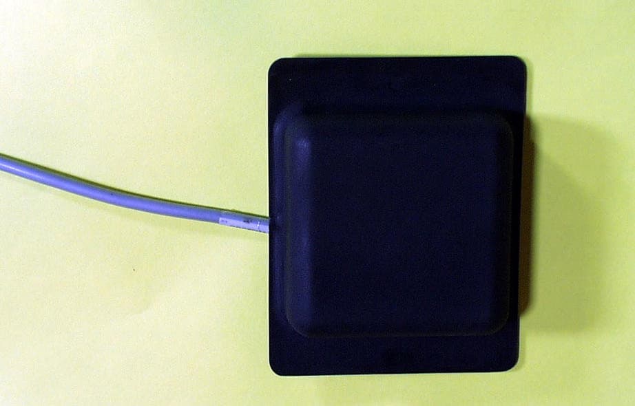
Click to zoom
Application Details
- Equipment Class
- DSR - Part 15 Remote Control/Security Device Transceiver
- Date of Grant
- Jun 14, 2004
- Application Purpose
- Original Equipment
- Date of Application
- Jun 14, 2004
- Equipment Note
- SPA Monitor Transceiver
- Frequency Range
- 433.92000000 - 433.92000000
- Company
- Balboa Instruments, Inc.
- Country
- United States
Documents & Files
Document Text
Text extracted from the exhibit documents filed with the FCC. Open a document above to read the original.
Users Manual
BALBOA SPAMONITOR O p e ra t i n g I n s t r u c t i o n s IMPORTANT: The user is cautioned that changes not expressly approved by Balboa Instruments, Inc. could void the user’s authority to operate the equipment. Page 2 TABLE OF CONTENTS Button Call Outs .................................................................................................................................. 3 Mode Operation .................................................................................................................................. 4 Sync/Jets Operation ............................................................................................................................ 4 Diagnostic Messages .......................................................................................................................... 5 ML900 Message Cross-Reference Table for Diagnostic Messages ...................................................6-7 ML900 Message Cross-Reference Table for Reminder Messages ...................................................... 7 Sounds ................................................................................................................................................ 8 Things to Avoid .................................................................................................................................... 8 CAUTION: Pull carefully with your fingernail from the top right corner to open. SYNC/JETS UP DOWN LIGHT MODE Light On Jets On Battery Low Heat On Page 3 Mode This button is used to switch between standard, economy, and sleep modes. Press MODE to enter mode programming, press “Down” to cycle through to desired mode (LCD flashes until confirmed), then press MODE to confirm selection. Standard mode maintains the desired temperature. Note that the last measured spa temperature displayed is current only when the pump has been running for at least 2 minutes. “Std” will appear on the display momentarily when you switch into Standard Mode. Economy mode heats the spa to the set temperature only during filter cycles. “Ecn” will appear solid when the temperature is not current and will alternate with the temperature when the temperature is current. Pressing SYNC/JETS while in Economy mode puts the spa in Standard-In-Economy mode, (“SE”) which operates the same as Standard Mode, then reverts to Economy Mode automatically after 1 hour. Press DOWN or UP followed by LIGHT to revert the mode to Economy immediately. Sleep mode heats the spa to within 20°F (11 °C) of the set temperature only during filter cycles. “SLP” will appear on the display until mode is changed. Sync/Jets The SYNC/JETS button on the SpaMonitor works like the JETS1 button on your main panel (or like the JETS button if your main panel has only one Jets button). Page 4 Diagnostic Messages Message Meaning The spa is operating in Standard Mode. The spa is operating in Economy Mode. The spa is operating Standard-in-Economy Mode. Sleep Mode has been activated by pressing a button combination on the user panel. The spa is operating in Test Mode. The Spa Monitor is unable to operate normally in Test Mode. Action Required Temperature display is current after pump has been running for at least 2 minutes. “Ecn” will appear solid on the display when the temperature is not current. “Ecn” will alternate with the temperature when the temperature is current. Operates the same as Standard mode, then reverts to Economy mode after 1 hour. Press MODE to switch directly to Economy mode. “SLP” will appear solid on the display when the temperature is not current. “SLP” will alternate with the temperature when the temperature is current. Contact your distributor or authorized dealer to have the spa switched back to User Mode. Consult your main panel documentation for the meaning and required action that corresponds to any additional three-letter diagnostic or reminder messages that may appear on the SpaMonitor display. If you use an ML900 main panel, consult the ML900 Cross-Reference Table on the next page to correlate the three-character message on the SpaMonitor with the 12-character message on the ML900. Page 5 ML900 Message Cross-Reference Table Diagnostic Messages SpaMonitor ML900 SpaMonitor ML900 Page 6 ML900 Message Cross-Reference Table Diagnostic Messages (Continued) SpaMonitor ML900 SpaMonitor ML900 alone alternating with temperature Reminder Messages SpaMonitor ML900 SpaMonitor ML900 Page 7 Sounds The Spa Monitor sounds an alarm when it detects the spa offline for more than 3 hours* or when the spa detects a condition that may require your attention (i.e. overheat). Press any button to reset the alarm. *The SpaMonitor detects the spa offline when it cannot communicate with the base unit. This can occur when the Spa Monitor is out of range or if there is a connection or power problem. Things to Avoid Be careful not to press multiple buttons together in normal use. Certain combinations of buttons put the SpaMonitor into special modes which are covered in the Installation Manual. Page 8
Users Manual
Test report #0400688FS FCC 15.231 for SPASIDE1 FCC ID: PYM-SPASIDE1 Tested June 5, 2004 AHD EMC Lab, 92723 M152, Dowagiac, MI 49047, (269) 424-7014 440571.DOC EXHIBIT B: Page 1 of 9 EXHIBIT D: USER INFORMATION [2.1033(A3)] The SPASIDE1 is not user installed. It is factory installed with an associated ‘spa controller’. A User’s Manual for the associated SPAHOME1 product is included for reference; file “EXD_Spa_Monitor_Manual.pdf”
Cover Letter(s)
AHD EMC Lab, 92723 M152, Dowagiac, MI 49047, (269) 424-7014 440573.DOC Request for CONFIDENTIALITY: Page 1 of 1 NVLAP ACCREDITED NARTE Certified Engineer Professional Engineer Federal Communications Commission Equipment Approval Services, P.O. Box 358315 Pittsburgh, PA 15251-5315 ELITE Electronic Engineering TCB Services 1516 Centre Circle Downers Grove, IL 60515-1082 Re: Request for exhibits to be kept confidential. FCC ID: PYM-SPASIDE1 Gentlemen: Pursuant to 47CRF 0.459, Balboa Instruments Inc., and Twisthink LLC requests that these listed exhibits be held confidential. Circuit Block Diagrams file names: EXB_Blockdia.doc Theory/Description of Operation, file name: EXB_operation.doc Schematics file names: EXB_CPUschem.jpg; EXB_TXschem.jpg; Balboa Instruments and Twisthink have invested considerable resources into developing this product. Having sections of Exhibit B, listed above, available to ‘competition’ would negate the advantage achieved in developing this product. Since this product type is a major product line for Balboa Instruments, not protecting the details of the design would result in a financial hardship for the company. The Federal Communications Commission will be notified, in writing, of any changes in the software/programming of the device that could affect the device’s RF characteristics. Your prompt consideration of this application for product certification will be greatly appreciated. Should you have any questions regarding the content of this report, kindly contact me. Sincerely, Ted Chaffee, Technical Lab Manager Narte Certified Engineer, #EMC-002025-NE tel/fax: 269. 424.7014 email: [email protected]
Cover Letter(s)
Dear Mr. Chaffee, The operation you propose would be acceptable under Section 15.231 except for 15.231(a)(4). Polling more than once per hour would not be permitted. However, manual transmissions from the remote in the home would be permitted as often as desired. >>> Ted Chaffee 10/20/03 01:17PM >>> ----- Original Message ----- From: Ted Chaffee To: Joe Dichoso Sent: Monday, October 20, 2003 9:43 AM Subject: Re: Transmitter operating under 15.231 Hello Ray Laforge, Joe Dichoso has asked me to forward a product concept for interpretation. We are trying to decide whether the product follows the guidelines to test under 15.231a or 15.231e. The description of the issue is below. Thanks for your assistance. -Ted Chaffee, AHD EMC lab [email protected] ----- Original Message ----- From: Joe Dichoso To: [email protected] Sent: Friday, October 17, 2003 5:02 PM Subject: Re: Transmitter operating under 15.231 Hello Ted, This interpretation will need to go through Ray. I think he already had sent around one that was very similar to this one. It sounds very familiar. Please contact him at [email protected] Thanks, Joe >>> Ted Chaffee 10/17/03 02:38PM >>> Hello Joe, In boldface below is the designer's explanation of how the transceiver in question fits into the FCC rules section 15.231a. My particular concern, that I mentioned to the designer, is how restrictive the definition of a safety related transmitter might be from the FCC viewpoint to allow it to operate under 15.231(a3). And that perhaps the product may be restricted in its output to the levels provided in 15.231(e) I hope the designer's statements below give you enough information to provide a response that will allow the product to be designed for the higher output power pursuant to 15.231a. Thanks, Ted Chaffee System description: Remote control of a hot tub or sauna type device. The system consists of two transceivers; one located in the home and one located on the hot tub. No external antennas will be used. The user will push a button on the remote in the home. The control information will be transmitted to the spa and the spa will verify reception of the command and send control information back to the remote. 15.231 a System will comply to the paragraph. Each will transmit only control signals, not voice, video or data. Each will transmit its own recognition code. 15.231 a.1 Manually instigated transmissions will cease within 5 seconds of a button being released. 15.231 a.2 Polling transmissions (1 per hour from the home) will cease within 1 second. 15.231 a.3 Since the system controls and has information concerning potentially scalding hot water, the system is considered safety related. As such 1 polling transmission per hour will be employed to determine system integrity as allowed in this paragraph. 15.231 a.4 If during the polling operation (1 per hour) an overheat condition is detected, the home device will reserve the right to poll more often while the overheat condition exists. 15.231 b The emissions will be limited as noted, and measured at 3 meters distance. 15.231 b.1 The system will comply as specified by the standard. 15.231 b.2 Averaging for each transceiver will be employed as specified in 15.35c. The pulse train for each transceiver will be less than .1 seconds. 15.231 b.3 The system will comply as specified by the standard. 15.231 c The system will comply as specified by the standard. 15.231 d The system will comply as specified by the standard. 15.231 e This section is not applicable. ----- Original Message ----- From: Joe Dichoso To: [email protected] Cc: Rich Fabina Sent: Thursday, October 09, 2003 2:47 PM Subject: Re: Transmitter operating under 15.231 Hello Ted, There's not enough information. It's probably best if you, for each requirement for 15.231(a-d) and 15.231(e), indicate how the device will or may not meet each rule. I can then comment on which rule you think may not be met. Regards, Joe >>> Ted Chaffee 10/08/03 03:08PM >>> Hello Joe Dichoso, We need your insight to determine whether the following transceiver should comply with 15.231a or 15.231e. The system consists of a transceiver pair. One at a remote "spa/hot tub" location and the second in the consumer's home. The premise is for the homeowner to receive "hot tub" status and alert of unsafe situation. My understanding of the system is the in-home unit polls the "spa" unit to verify the remote transmitter function, water temp, and other spa status. Here are statements emailed to me from the engineer/designer to help explain the product --- The main stream strategy is to have a 1/hr poll from the home (master) to the subordinate transmitters (spa). (there are negative battery implications of having the home side listening, and the 8dB would put us at marginal range The spa response to the poll will simultaneously verify transmitter function, water temp, and spa status. The time constant for the relatively large amount of water is very slow, so the customer feels 1 check per hour will be sufficient. If the spa loses power, it will not respond to the poll. f we do not get a response after 2 or 3 hours we will assume either the transmitter has failed or power has been lost to the spa. 15.231.a.3 allows verification of system transmitters in safety related systems at a rate of once per hour. I think it is reasonable to consider this a "safety related system" due to the danger of scalding, especially if children are involved. Joe, can you make a determination from the information here whether this product can be tested to the limits of 15.231a? Thanks for your help. Regards, Ted Chaffee, NCE AHD EMC lab [email protected]
ID Label/Location Info
Test report #0400688FH FCC 15.231 for SPASIDE1 FCC ID: PYM-SPASIDE1 Tested June 5, 2004 AHD EMC Lab, 92723 M152, Dowagiac, MI 49047, (269) 424-7014 440561.DOC Exhibit A: Page 1 of 1 EXHIBIT A: EQUIPMENT LABEL [2.925, 2.926, 2.1033(B2,7), 15.19(A3)] LABEL INFORMATION The FCC Identifier assigned to the EUT is FCC ID: PYM-SPASIDE1 [the last character is the numeral one]. This identifier will be permanently molded into the outside exterior of the SPASIDE1 plastic housing. A photograph of a prototype unit with the required verbiage and its location on the unit’s housing appears below.
RF Exposure Info
Test report #0400688FS FCC 15.231 for SPASIDE1 FCC ID: PYM-SPASIDE1 Tested June 5, 2004 AHD EMC Lab, 92723 M152, Dowagiac, MI 49047, (269) 424-7014 440581.DOC Misc. EXHIBIT: Page 1 of 1 MISC. EXHIBIT: RF EXPOSURE INFORMATION [2.1093(C)] The manufacturer and applicant: Balboa Instruments Inc. 1382 Bell Avenue Tustin, CA 92780-6430 Product: A 433.92MHz transceiver Model: SPASIDE1 Applicable Rules: 47CFR Part 15.231 Pursuant to 47CFR Part 1.1307(b), 47CFR Part 2.1091(c), and 47CFR Part 2.1093(c) this transmitting device, compliant to 47CFR Part 15.231, is categorically excluded from evaluation regarding the Maximum Permissible Exposure of RF energy.
Test Report
Test report #0400688FS FCC 15.231 for SPASIDE1 FCC ID: PYM-SPASIDE1 Tested June 5, 2004 AHD EMC Lab, 92723 M152, Dowagiac, MI 49047, (269) 424-7014 440572.DOC EXHIBIT E: Page 1 of 19 EXHIBIT E: REPORT OF MEASUREMENTS [2.1033(B6)] Test Report for FCC ID: PYM-SPASIDE1 FCC Part 2.1031, Part 15 Subpart C(15.231) Report #0400688FS Issued 06/05/04 MODEL SPASIDE1 433.92MH Z TRANSCEIVER Prepared for: Mr. Tony Pipitone Balboa Instruments Inc. 1382 Bell Avenue Tustin, CA 92780-6430 Test Date(s): March 25, April 26, May 27, June 1, 5, 2004 Report prepared by: Report reviewed by Ted Chaffee, NCE Data recorded by: Gordon Helm, NCE Ted Chaffee, NCE Test report #0400688FS FCC 15.231 for SPASIDE1 FCC ID: PYM-SPASIDE1 Tested June 5, 2004 AHD EMC Lab, 92723 M152, Dowagiac, MI 49047, (269) 424-7014 440572.DOC EXHIBIT E: Page 2 of 19 TABLE OF CONTENTS EXHIBIT E: Report of Measurements [2.1033(b6)] .....................................................................................1 TABLE OF CONTENTS.........................................................................................................................2 Statements Concerning this Report.......................................................................................................3 Manufacturer/Applicant [2.1033(b1)] ....................................................................................................4 Measurement/Test Site Facility & Equipment........................................................................................4 Test Site [2.948, 2.1033(b6)] ......................................................................................................4 Measurement Equipment Used.............................................................................................................4 Environment...........................................................................................................................................4 Tested Configuration /Setup: [2.1033(b8)] ............................................................................................5 Support Equipment & Cabling .......................................................................................................5 Setup Diagrams .............................................................................................................................5 Description of Equipment Under Test............................................................................................6 Summary of Results: .............................................................................................................................6 Changes made to achieve compliance..........................................................................................7 Standards Applied to Test: [2.1033(b6)]................................................................................................7 Test Methodology: [2.1033(b6)].............................................................................................................7 Line Conducted..............................................................................................................................7 FORMULAS AND SAMPLE CALCULATIONS: .............................................................................9 Determining the Signal average of the SPASIDE1........................................................................9 Test Data [2.1033(b6)].........................................................................................................................12 Modulation Characteristics ..........................................................................................................12 Line Conducted Measurements: [15.207]....................................................................................13 Occupied Bandwidth [15.231(c)]..................................................................................................15 Restricted Bands: [15.205]..........................................................................................................16 Radiated Field Strength Measurements: [15.231(b), 15.205] ....................................................17 Test report #0400688FS FCC 15.231 for SPASIDE1 FCC ID: PYM-SPASIDE1 Tested June 5, 2004 AHD EMC Lab, 92723 M152, Dowagiac, MI 49047, (269) 424-7014 440572.DOC EXHIBIT E: Page 3 of 19 Statements Concerning this Report NVLAP Accreditation: NVLAP Lab Code 200129-0 The scope of AHD accreditation is the test methods of: IEC/CISPR 22: Limits and methods measurement of radio disturbance characteristics of information technology equipment. FCC Method – 47 CFT Part 15: Digital Devices. AS/NZS 3548: Electromagnetic Interference – Limits and Methods of Measurement of Information Technology Equipment. IEC61000-4-2 and Amend.1: ElectroStatic Discharge Immunity IEC61000-4-5: Surge Immunity Test Data: This test report contains data covered by the NVLAP accreditation. Subcontracted Testing: This report does not contain data produced under subcontract. Test Traceability: The calibration of all measuring and test equipment and the measured data using this equipment are traceable to the National Institute for Standards and Technology (NIST). Limitations on results: The test results contained in this report relate only to the Item(s) tested. Any electrical or mechanical modification made to the test item subsequent to the test date shall invalidate the data presented in this report. Any electrical or mechanical modification made to the test item subsequent to this test date shall require an evaluation to verify continued compliance. Limitations on copying: This report shall not be reproduced, except in full, without the written approval of AHD. Limitations of the report: This report shall not be used to claim product endorsement by NVLAP, FCC, or any agency of the US Government. Statement of Test Results Uncertainty: Following the guidelines of NAMAS publication NIS81 and NIST Technical No…
Text truncated - open the document above for the full version.
Contact Information
Applicant
Tony Pipitone(Electrical Design Engineer)
Technical Contact
Balboa Instruments Inc.Tony Pipitone
[email protected]714-384-0384
1382 Bell Ave. · Tustin, California · United States
Non-Technical Contact
AHDTed N Chaffee
[email protected]269-424-7014
Test Firm
AHD EMC LaboratoryGordon Helm
Technical Specifications
| # | Rule Parts | Frequency Range | Power Output |
|---|---|---|---|
| 1 | 15.231 | 433.92 MHz - 433.92 MHz | - |
Other Applications from Balboa Instruments, Inc.
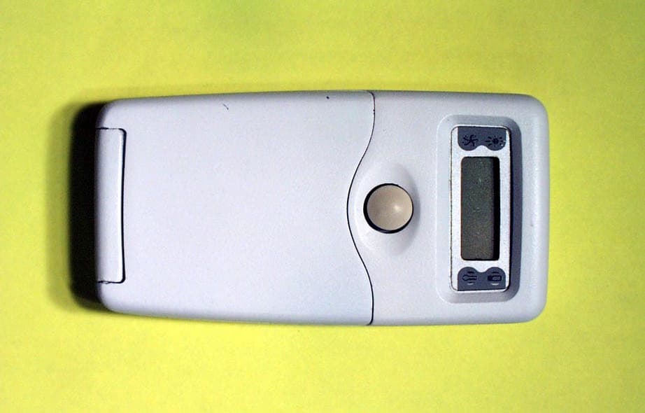
PYM-SPAHOME1
Jun 14, 2004SPA Monitor Transceiver
Equipment Class
DSR - Part 15 Remote Control/Security Device Transceiver