PYVR63311Alert Monitor
All American Sports Corporation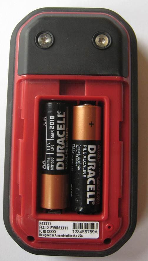
Click to zoom
Application Details
- Equipment Class
- DXT - Part 15 Low Power Transceiver, Rx Verified
- Date of Grant
- Jul 17, 2013
- Application Purpose
- Original Equipment
- Date of Application
- Jun 10, 2013
- Equipment Note
- Alert Monitor
- Frequency Range
- 2400.00000000 - 2480.00000000
- Country
- United States
Documents & Files
Document Text
Text extracted from the exhibit documents filed with the FCC. Open a document above to read the original.
Users Manual
P/N R63314 v1.0 User Guide COPYRIGHT© 201 3 RIDDELL INC. ALL RIGHTS RESERVED. REPRODUCTION OF THIS MANUAL IN ANY MEDIUM WITHOUT T HE EXPRESS PERMISSION OF RIDDELL IS PROHIBITED. LIMITED RIGHTS NOTICE TECHNICAL DATA/DOCUMENTATION P/N R63314 v1.0 Page | ii CONTENTS CONTENTSCONTENTSCONTENTS Introduction ...................................... ............................................. 1 Warnings .......................................... .............................................. 2 System Overview.................................... ........................................ 3 InSite Setup ...................................... .............................................. 6 Overview .......................................... ................................................... . 6 Alert Monitor ..................................... ................................................... 7 Battery Installation and Charging ................. ............................................. 7 Controls and Indicators ........................... .................................................. 7 Navigation – Screens & Menus ...................... ........................................... 9 Player Unit ....................................... ................................................... 13 Battery Care ...................................... ................................................... .. 13 Controls and Indicators ........................... ................................................ 13 Installation into Helmets.......................... ............................................... 16 InSite Player Management Software ................. ................................... 18 InSite Configuration .............................. .............................................. 19 Adding Alert Monitors ............................. ............................................... 19 Adding Player Units ............................... ................................................. 2 1 Creating Players and Assigning Player Units ....... ..................................... 23 Managing Multiple Teams ........................... ........................................... 26 Transferring Players or Equipment between Teams ... ............................. 26 Deleting Players or Equipment ..................... ........................................... 28 P/N R63314 v1.0 Page | iii System Settings ................................... ................................................... 29 Using InSite ...................................... ............................................ 31 Before Use ........................................ .................................................. 31 During Use ........................................ .................................................. 32 Alert Thresholds and HITsp ........................ ............................................. 33 After Use ......................................... ................................................... . 34 Long-Term (End-of-Season) Storage ................. ................................... 36 Maintenance ....................................... ......................................... 36 Reconditioning .................................... ................................................ 36 Software and Firmware Updates ..................... .................................... 37 Batteries ......................................... ................................................... . 42 Cleaning InSite Equipment ......................... .......................................... 43 Troubleshooting ................................... ........................................ 43 Alert Monitor ..................................... ................................................. 4 4 Player Unit ....................................... ................................................... 46 Sending Test Alerts (Test Mode) ................... .......................................... 46 InSite Player Management Software ................. ................................... 48 Contact Information ............................... ...................................... 49 Compliance Information............................. .................................. 49 Warranty .......................................... ............................................ 50 P/N R63314 v1.0 Page | 1 INTRODUCTION INTRODUCTIONINTRODUCTIONINTRODUCTION For over 80 years, Riddell has been the recognized leader in helmet technology and innovation. Founded with the mission to make sports equipment safer, better and easier to use, Riddell continues to address the evolving protective equipment needs of the athl ete. Today, Riddell equipment is seen on football fields from coast-to- coast, protecting every level of player—from youth athletes to NFL pr ofessionals. Riddell is always working on the next generation of helmet technology. Its newest product introduction, the Riddell InSite Impact Response System, is the latest in a series of recent innovat ions incorporating state-of-the-art features that are new to the footb all field. Riddell InSite is a new integrated monitoring and alerting tool d esigned specifically for the proactive protection of footba ll players. As the first to implement head impact monitoring and recording syst ems, Riddell developed InSite using data collected by Riddell’s Sideline Respons e System (SRS) with Head Impact Telemetry (HITS). Sin ce 2003, Riddell SRS has analyzed millions of impacts from youth to elite football competition, and its data has led to impactful chan ges to rules, how the game is played and coached, and has informed new he lmet designs with enhanced protective benefits. Riddell InSite utilizes new integrated technology t o monitor and record significant head impacts sustained during a footbal l game or practice. Coaches and other sideline staff will now have Ridd ell InSit…
Text truncated - open the document above for the full version.
Operational Description
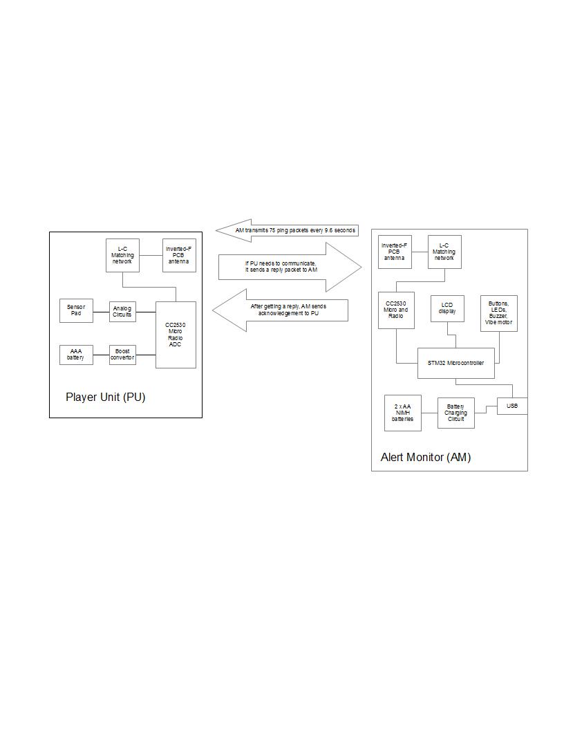
Riddell – CONFIDENTIAL 9/272012 Page 1 of 2 TECHNICAL MEMORANDUM DIN: MEM-016-20121010-01 TO: Kyle, Green Mountain Electromagnetics CC: DATE: November 14, 2012 FROM: Aaron Buck SUBJECT: Riddell InSite – Description of Product Operation for FCC Hello Kyle – Here is an outline of the RF system and operation for the Riddell InSite product: 1. System Technology a. Our system uses the CC2530 family of components from Texas Instruments, specifically the CC2530 variant in the Player Unit , and CC2531 variant in the Alert Monitor (handheld transceiver). We are using a custom time division multiplexing protocol developed to optimize power consumption given required data throughput. Here are some representative specifications on the technology: Characteristic Specification Value RF Link Communication Range (m) <=50 # of nodes supported 150 Data throughput (kbps) 250 Operating Frequency (Mhz) 2.405 to 2.480 Ghz in 5 Mhz increments ISM Data Modulation Direct-sequence Spread Spectrum (DSSS – 16 channels) PHY and MAC Layer 802.15.4 compatible Network Toplogy Primarily Star with Coordinators (other Basestations) Environmental Operating Temperature (°C) -20 to +40 deg C Relative Humidity (%RH) 100% non-condensing Impact resistance (g) >= 300 g Water Resistance 1m waterproof (Player Unit), rain & splash resistant (Alert Monitor) Operating Battery Life, Player Unit 1-year, battery replaced yearly @ factory reconditioning Battery Life, Alert Monitor 1-week, rechargeable via USB Measurement capabilities Impact Linear Acc Proxy Range(g) 15-300 Impact HIC/GSI Proxy range >= 2000 Impact Location 90 degree increments in coronal plane to determine impact quadrant (front,L/R,back) and top of head Cumulative (days) Cumulative HITsp Index - 7 day time-weighted rolling window Sensor Type Thin Film Alert Threshold Adjustable HITSp threshold, specific to playing position & skill level. Single- and multiple-event Alert types. Physical Size (width” x length” x height”) 3.8” x 1.5” x 0.5” (Helmet-mounted Player Unit) Weight (grams) 76 g (2.7 oz) Helmet fit Models available for Riddell 360 & Revolution Speed helmets Warranty 1 year Reconditioning Interval 1-year (recondition each year) Removable Yes Washable (Laundry) No
Test Report
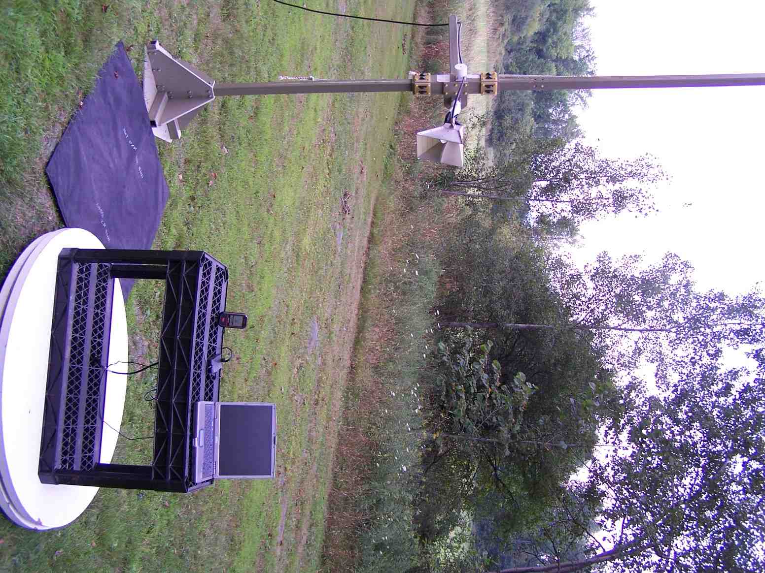
Serial No. GM212047f FCC TEST REPORT FOR THE ALL AMERICAN SPORTS CORPORATION RIDDELL MODEL R63311 ALERT MONITOR (FCC ID PYVR63311) Prepared for: All American Sports Corporation Riddell 9801 West Higgins Road, 8 th Floor Rosemont, IL 60018 USA Submitted by: Green Mountain Electromagnetics, Inc. (802) 388-3390 (802) 388-6279 Fax [email protected] 219 Blake Roy Road • Middlebury, Vermont 05753 Copyright: September 20, 2012 This report shall not be reproduced, except in full, without the written approval of GME. GME Test Lab Cert 898.01 Serial No. GM212047f FCC ID PYVR63311 Riddell, September 2012 Page 2 of 43 GME, Inc. • 219 Blake Roy Road • Middlebury, VT 05753 • Tel: 802-388-3390 • gmelectro.com GME All American Sports/Riddell FCC Testing At Green Mountain Electromagnetics, Inc. Unit: Model R63311 Alert Monitor (FCC ID PYVR63311) Received: 8/22/12 Tested: August 23 - 28, 2012 I. Applicable Standards: The units described in this report were measured for verification of compliance with "47 CFR, Part 15 – Radio Frequency Devices, Subpart C: Intentional Radiators," paragraph 15.207, Conducted Limits, paragraph 15.209, Radiated Emissions, and 15.249, Operation within the 2400 – 2483.5 MHz Band. Measurement procedures were in accordance with ANSI C63.4, "Methods of Measurement of Radio-Noise Emissions from Low-Voltage Electrical and Electronic Equipment in the Range of 9 kHz to 40 GHz (2009)," and FCC OET Bulletin 65, "Evaluating Compliance with FCC Guidelines for Human Exposure to Radiofrequency Electromagnetic Fields (Jan. 2001)." Additionally, the units described in this report were measured for certification with the Code of Federal Regulations Chapter 47 – "Telecommunication, Part 2 – Frequency Allocations and Radio Treaty Matters: General Rules and Regulations, Subpart J – Equipment Authorization Procedures." Measurements required were per paragraphs 2.1046 RF Power Output, 2.1049 Occupied Bandwidth, 2.1053 Field Strength of Spurious Radiation, 2.1055 Frequency Stability, and 2.1093 Radiofrequency Radiation Exposure Evaluation: Portable Devices. II. Unit Tested: The Riddell Model R63311 (FCC ID PYVR63311) Alert Monitor is used in conjunction with the Model R64001 (FCC ID PYVR64001) Player Unit for football-player helmet impact sensing and recording. The Alert Monitor consists of a hand-held plastic enclosure with LCD screen, keypad, and the 5-channel (2.410, 2.425, 2.450, 2.475 and 2.480) GHz intermittent data transceiver mounted in the enclosure. The Alert Monitor uses two AA batteries and may also be powered by a USB, AC power supply. It employs the Texas Instruments CC2530F series, IEEE 802.15.4 compliant chip-set with an integral antenna. Serial No. GM212047f FCC ID PYVR63311 Riddell, September 2012 Page 3 of 43 GME, Inc. • 219 Blake Roy Road • Middlebury, VT 05753 • Tel: 802-388-3390 • gmelectro.com GME The table below describes the unit that was subjected to measurements determining compliance with applicable EMC standards: Model Manufacturer Serial Number R63311 Alert Monitor Riddell 00020 The following table describes the system physical and electrical properties: Model Volts H/W/D in cm R63311 Alert Monitor EUT: 3-VDC Batteries PS: 100-240 AC, 100 mA, 50/60 Hz 12/6/3 The following table describes the support equipment used during testing: Product Manufacturer Model # Serial Number Laptop PC Dell PP05L CN-0X2034-48643-3A6 PC Power Supply Dell 1650-05D CN-05V092-7165-ABH Power Supply (AC/USB) Phihong PSM03A-050Q1 PC04001046 Signal cables were used for testing and are supplied by the manufacturer. The following table describes the system cables: Cable Mfr/Description Agency Rating Signal High-Speed USB UL 338413 Riddell “InSite” software was used to evaluate the unit. III. Measurement Location: The GME laboratory and Open Area Test Site (OATS) are located at 219 Blake Roy Road, Middlebury, VT. The OATS is a 10/3/1-meter site complete with antenna positioner, ground plane and motorized turntable. The OATS is constructed in accordance with ANSI C63.7-2005 and complies with the requirements for radiated emissions testing in ANSI C63.4-2009 and CISPR standards. GME is internationally accredited by the American Association for Laboratory Accreditation (A2LA) and meets the quality requirements in ISO/IEC 17025 (2005), "General Requirements for the Competence of Testing and Calibration Laboratories." Serial No. GM212047f FCC ID PYVR63311 Riddell, September 2012 Page 4 of 43 GME, Inc. • 219 Blake Roy Road • Middlebury, VT 05753 • Tel: 802-388-3390 • gmelectro.com GME IV. Summary of Results: The Riddell Model R63311 (FCC ID PYVR63311) Alert Monitor complies with the requirements in FCC 47 CFR, Paragraphs 2 and 15. Section X contains the results summarized in the table below. CFR 47 Frequency Specified Measured Test Mode/Port Paragraph or Range Values Values 1 RF Power Output Transmit 2.1046 15.249 2.465 GHz -13 dBm (<50,000 uV/m) -25 dBm 2 Occupied Bandwidth Transmit 2.1049 15.249 20-dB down at 0.5% of Fundamental <12 MHz 3 MHz 3 Frequency Stability Transmit 2.1055 2.4 – 2.4835 GHz Battery End Point 2.4 – 2.4835 GHz 4 Radiated and Spurious Emissions Enclosure 15.209 15.249 2.1053 30 – 88 MHz 88 – 216 MHz 216 – 960 MHz 960 – 24 GHz 40 dBuV/m 43.5 dBuV/m 46 dBuV/m 54 dBuV/m Within 3m and 1m Limits 5 Conducted Emissions AC Port 15.207 150 kHz – 500 kHz 0.5 – 5 MHz 5 – 30 MHz 66-56 dBuv 56 dBuV 60 dBuV Within All Limits 6 Exposure Evaluation Enclosure 2.1093 2.4 GHz 0.08 W/kg Body 1.6 W/kg 1g Vol Within All Limits Exploratory measurements indicate maximum radiation is found when antenna polarization is aligned with the EUT antenna and when antenna is pointed directly at the EUT at scan heights >10% of EUT height. Serial No. GM212047f FCC ID PYVR63311 Riddell, September 2012 Page 5 of 43 GME, Inc. • 219 Blake Roy Road • Middlebury, VT 05753 • Tel: 802-388-3390 • gmelectro.com GME Testing was performed by Kyle R. Kowalczyk, president, Green Mountain Electromagnetics and requested by: All American …
Text truncated - open the document above for the full version.
Contact Information
Applicant
Thad Ide(Senior Vice President R&D)
Technical Contact
Green Mountain ElectromagneticsKyle Kowalczyk
[email protected]8023883390
219 Blake Roy Road · Middlebury, Vermont · United States
Non-Technical Contact
Green Mountain ElectromagneticsKyle Kowalczyk
[email protected]8023883390
Test Firm
Green Mountain Electromagnetics, IncorporatedKyle Kowalczyk
Technical Specifications
| # | Rule Parts | Frequency Range | Power Output |
|---|---|---|---|
| 1 | 15C | 2.40 GHz - 2.48 GHz | - |
Other Applications from All American Sports Corporation
PYVR64001
Jul 18, 2013Alert Monitor
Equipment Class
DXT - Part 15 Low Power Transceiver, Rx Verified