PZZPC-MODEM-2-00Smart interface which gets orders from PC and tran
PHANTOM II Production Ltd.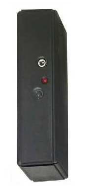
Click to zoom
Application Details
- Equipment Class
- DSC - Part 15 Security/Remote Control Transmitter
- Date of Grant
- Mar 05, 2002
- Application Purpose
- Original Equipment
- Date of Application
- Nov 06, 2001
- Equipment Note
- Smart interface which gets orders from PC and tran
- Frequency Range
- 433.92000000 - 433.92000000
- Company
- PHANTOM II Production Ltd.
- Country
- Israel
Documents & Files
Document Text
Text extracted from the exhibit documents filed with the FCC. Open a document above to read the original.
Users Manual
For Leonardo E-1 Interface (C) 1999 Phantom II, LLC ™ 4.1 Control Software (C) Phantom II, LLC. 2 Software Manual Quick Help to Technologica software Welcome to Technologica software. This guide summarizes the primary elements needed to know in order to work with Technologica . The guide has two parts: I. “General Concept” and a list of the Primitive Commands. II. “General Structure” and how to use the software. I. General Concept Technologica is a Control Software designed to work with Leonardo Interface. Technologica is used to control models built with K’NEX parts. In other words, you build K’NEX models using motors, lights, sensors etc., attach them to the Leonardo interface box and use Technologica to control the operation of the model. Technologica is designed to be a highly user-friendly software and does not require any previous knowledge in computers or programming. Technologica is provided in four levels: 1. Direct Level is for young users. 2. Automatic Level is for new or novice users. 3. Interactive Level is for advanced users. It expands the Automatic Level to work with K’NEX sensors. 4. Collaborative Level expands the Interactive Level to work with several Leonardo interfaces using communication. Each Leonardo interface can send and receive information or commands from other Leonardo interfaces. In general, when you work with Technologica you work on a project . A project is a set of Procedures you design. A Procedure is an organized set of Primitive Commands and other Procedures . The Primitive Commands and the Procedures are used to interact with the ports on the Interface Box thus, operating the K’NEX model. All Commands and Procedures are actually buttons on the screen. To operate (execute) a command, simply Click it. Note: Direct Level uses only several of the basic Primitive Commands without the option of creating and editing procedures. (C) Phantom II, LLC. 3 Software Manual The principle of Technologica software is that at any given time, there is only one Output Port (A to D) that the computer talks-to. This port is called the talk-to port. From now on , every command is addressed to this Output Port. If you want to change the talk-to port, click a new one on the Interface image. Primitives Commands Talk-To Address an Output Port (A to D). On Turn on the selected Output Port. Off Turn off the selected Output Port. Reverse-Direction, Set-Direction Change/Set the Direction of the selected Output Port. Set-Power Set the level of electricity power of the selected Output Port. Flash Turn the selected Output Port on and off repeatedly. Delay Pause the flow of commands for a defined period. Sound Produces a tone defined by its pitch and duration. (C) Phantom II, LLC. 4 Software Manual Repeat Repeat the following command (button), the number of times as set by the repeat button. Utilities Buttons Exit Button Allows you to return back to previous screen or exit the program. Printing Button Allows you to print the current screen. Help button Gives information about all the software instruction and everything else you can see on the screen. Procedure Editor Moves you to the procedure editor to define or edit a procedure content. Picture Editor Moves you to the picture editor to draw or edit a procedure icon. Power Supply Status By clicking on this icon you get information on the power supply status of the Leonardo interface. (C) Phantom II, LLC. 5 Software Manual Interactive Level Concept If you are using the Direct Level or Automatic Level of Technologica you may skip this chapter and read it later when you are more experienced with Technologica concepts . Interactive Level expands the principle to work with the K’NEX sensors concerning the input ports (1 to 4). That is, at any given time there is only one input port that the computer listens-to. This port is called the listen-to port . All the input commands address this port. If you want to change the listen-to port, click a new one. After you have attached and defined a sensor to an input port, you can watch the value it is currently reporting appear below the sensors image. These values are updated every half second. Some of the sensors can operate in two types of operation. Meaning, the same K’NEX sensor can report different values according to the specific type defined to it. For example, the angle sensor can either report the rotation angle or the number of rotations. Therefore, you should set the sensor type according to the specific operation you want it to perform. Additional Primitive Commands (Interactive Level and Collaborative Level only) Listen-to Address an input port (1 to 4). If - Then Test the current listen-to port according to the condition set on the button. If the result is true, the following command (button) will be executed. Otherwise, it will be skipped. (C) Phantom II, LLC. 6 Software Manual If-Then-Else Test the current listen-to port according to the condition set on the button. If the result is true, the first following command will be executed and the second following command will be skipped. Otherwise, the first following command will be skipped and the second following command will be executed. Wait-Until Test the current listen - to port according to the condition set on the button. As long as the result is false, the computer waits , as soon as the result is true, the execution of the following commands continue. Reset Used to reset and adjust the values of the sensor ports (1 to 4) according to the kind of sensor. Not all types of sensors can be reset. Condition Primitives (Interactive Level and Collaborative Level only) The primitives: if , if-else and wait-until are called condition primitives. These primitives test the current listen-to input port, according to the kind of sensor that is defined for that port and the condition that is defined by the user for that primitive. Each condition command has two parameters: operator and value . The operator can be either: = , ≠ , < , ≤ , ≥ , >…
Text truncated - open the document above for the full version.
Block Diagram
PC-MODEM-2-00 Block diagram Communication Micro Controller Power Supply
External Photos
PC-MODEM-2-00 External photo
ID Label/Location Info
PC-MODEM-2-00 ID Label. The label is attached on the rear panel of PC-Modem PC Adapter Part # 92109 Phantom II, LLC http://www.phantom2.com Caution - Electric Toy: As with all electrical products precautions should be observed during handling and use to prevent electric shock. FCC ID : PZZ-PC-MODEM-2-00 Complies with part 15 of the FCC rules. Age 6+ Made in Israel
ID Label/Location Info
PC-MODEM-2-00 ID Label. The label is attached to the back panel of PC-Modem PC Adapter Part # 92109 Phantom II, LLC http://www.phantom2.com Caution - Electric Toy: As with all electrical products precautions should be observed during handling and use to prevent electric shock. FCC ID : PZZPC-MODEM-2-00 Complies with part 15 of the FCC rules. Age 6+ Made in Israel
Internal Photos
PC –Modem-2-00 internal photos Photo #1 Two PWB are shown: Main board (horizontal) and Modem board (vertical) Photo #2 Two PWB are shown: Main board (horizontal) and Modem board (vertical) Photo #3: Main board Photo #4: Main board
Operational Description
PC-Modem-2-00 Operational Description The PC-MODEM-2-00 and LEONARDO-2-00 are the parts of an educational system. The PC-MODEM gets the program commands from PC and interacts remotely with a number of LEONARDO units which activate the appropriate executive mechanical devices according with program commands. PC-MODEM-2-00 General information: Operation Frequency433.92 MHz ModulationPulse width modulation Type of antennaPrinted coil Power supply12 VDC external adapter FunctionRemote transmissions to LEONARDO transmitters following the program commands. Computer FCC ID: PZZ-PC-MODEM-2-00 PC cable 12 VDC FCC ID: PEO-LEONARDO-2-00
Schematics
PC-MODEM-2-00 Schematic diagram Schematic description: The transmitter schematic is based on the transistor MBTH10 (Q2) which uses SAW- resonator X1 at work frequency 433.92 MHz. The modulation is provided by Motorola microcontroller 68HC705KJ1 which uses oscillator Y1 at 4 MHz. Receiver Controller Transmitter TX RX VC C+12V VC C VC C VC C +12V AN T1 AN TENN A R1 1k R5 10k C12 3. 3pF Q1 MB TH 1 0 L2 1uH C15 2-7pF R5 10k C12 3. 3pF R12 470R C3 4. 7n C13 3. 3pF PC B C OI L R10 4. 7k C7 100pF OP T R7 10k C4 2. 2nF U?A TL062 + - 3 2 1 R1 2M U?B TL062 + - 5 6 7 R8 10k C16 2. 2nF R9 10k C1 4. 7uF J? CON8 12345678 Y1 4m HZ c10 33pF C9 33pF U? 68hc705kj1 RST 1 OS C1 2 OS C2 3 PB3 4 PB2 5 VC C 6 GN D 7 PA7 8 PA6 9 PA5 10 ; PA4 11 PA3 12 PA2 13 PA1 14 PA0 15 IRQ 16 X1 433. 92MHz Q2 MB TH 1 0 R2 330R C8 1nF C14 1. 2pF L1 1uH PC B C OI LPC B C OI L R14 220R C11 6. 8pF
Test Report
Test Report No.8012306767 For Phantom II production Ltd. PC-MODEM Model: PC-MODEM From The Standards Institution Of Israel Industry Division Telematics Laboratory EMC Section Certificate No.1487-01 Test Report No.:8012306767Page 1 of 20 Pages Title: Test on PC-MODEMModel: PC-MODEM Order placed by: Phantom II production Ltd. Address: Kibutz Yakum 60972, Israel Sample for test selected by: The orderer T he date of test: 05/06/2000 Description of Equipment Under T est (EUT ): PC-MODEM Model: PC-MODEM Manufactured by: Phantom II productio n Ltd. ! CFR 47 FCC Rules and Regulations: Part 15. Radio frequency devices. Subpart B: Unintentional radiators. Subpart C: Intentio nal radiators. Sec. 15.231 This Test Report contains 20 pages and may be used only in full. This Test Report applies only to the specimen tested and may not be applied to other specimens of the same product. Test Report No.:8012306767Page 2 of 20 Pages Title: Test on PC-MODEMModel: PC-MODEM Table of Contents 1.EUT DESCRIPTION AND OPERATION3 1.1.G EN ERA L D ESCRIP TIO N :3 1.2.EUT' S SUB - ASSEMBLI ES LIS T :4 1.3.EUT CONNECTORS LIST :4 1.4.A U XI LI ARY EQ UIPM EN T USED :4 1.5.EUT S ETUP AND OP ERATION :5 2.TEST SPECIFICATION, METHODS AND PROCEDURES6 3.ADDITIONAL DEVIATIONS OR EXCLUSIONS FROM THE TEST SPECIFICATIONS6 4.MEASUREMENTS, EXAMINATIONS AND DERIVED RESULTS7 4.1.L OCATION OF THE T EST S ITE :7 4.2.T ES T CO N DITIO N :7 4.3.E MISSION TESTS :7 4.4.I NITIAL VISUAL CHECK AND FUNCTIONAL TEST :7 4.5.C O N DUCTED EM ISSIO N TES TS :8 4.6.R ADIATED EMISSION TEST :11 5.COMPLIANCE WITH SPECIFICATION15 6.APPENDIX 1: TEST EQUIPMENT USED16 7.APPENDIX 2: ANTENNA FACTOR AND CABLE LOSS17 8.APPENDIX 3: TEST CONFIGURATION ILLUSTRATION19 Test Report No.:8012306767Page 3 of 20 Pages Title: Test on PC-MODEMModel: PC-MODEM 1. EUT Description and operation 1.1. General description: Description of Equipment Under T est (EUT ): PC-MODEM Model: PC-MODEM Manufactured by: Phantom II productio n Ltd. The EUT is an adapter between the PC / MAC and the LEONARDO. The PC-Modem communicates with the PC/MAC via a cable, and with the LEONARDO by RF communication . EUT’s Fundamental frequency = 433.92 MHz. The EUT's dimensio ns are: 5.5 x 12 x 3 cm approx. The EUT's power co nsumption from 220/110 VAC to 9-12 VDC Adaptor. The EUT's block diagram is sho wn in Figure 1. Figure 1 :EUT's block diagram Communication Micro Controller Power Supply Test Report No.:8012306767Page 4 of 20 Pages Title: Test on PC-MODEMModel: PC-MODEM 1.2. EUT's sub-assemblies list: EUT’s sub-assemblies list is detailed in table 1. Table 1- Sub-assemblies list FunctionMarking/Serial No./ Model Main PC-MODEM boardLEONARDO Ver: 3.0 Modem boardMODEM Ver: 4B AC/DC Adaptor 110 VAC/12 VDCModel STA-4112 C-9 mfr Knex 1.3. EUT connectors list: A list of the EUT's connectors is detailed in table 2. Table 2- Connector list No. Connector's name Connector's type Type of cable Length (m) Location No. of identical connectors 1DC Power jac k DS-210B Typical <3Side1 2Stereo jack3.5mm ST- 2 PC Cable #92108 by Phantom II 1Side 1 1.4. Auxiliary equipment used: The auxiliary equipment used is detailed in table 3. Table 3 - Auxiliary equipment used NameManufact urer ModelSerial No.Remarks Laptop-Twinhead Model SLMNOTE-5 FCC ID: FXGPG2 - Test Report No.:8012306767Page 5 of 20 Pages Title: Test on PC-MODEMModel: PC-MODEM 1.5. EUT setup and operation: The EUT was setup as shown in Figure 2 and operated in operation modes as detailed in table 5. Table 5 - Modes of operations No.Mode of operationTest setup Emissions Measurements 1StandbyFig.2per FCC Part 15 Subpart B 2TransmissionFig.2per FCC Part 15 Subpart C Figure 2 – EUT Test Setup PCPC-MODEM Power Supply 9 - 12Vdc Test Report No.:8012306767Page 6 of 20 Pages Title: Test on PC-MODEMModel: PC-MODEM 2. Test specification, Methods and Procedures Test Specification : ! CFR 47 FCC Rules and Regulations: Part 15. Radio frequency devices. Subpart B: Unintentional radiators. Subpart C: Intentio nal radiators. Sec. 15.231 Methods and Procedures : ! ANSI C63/4/1992: "American National Standard for Methods of Measurement of Radio- Noise Emissions from Low-Voltage Electrical and Electronic Equipment in the range of 9 kHz to 40 GHz. 3. Additional deviations or exclusions from the test specifications Not applicable. Test Report No.:8012306767Page 7 of 20 Pages Title: Test on PC-MODEMModel: PC-MODEM 4. Measurements, examinations and derived results 4.1. Location of the Test Site: Conducted emission test was carried out in the EMC laboratory of the Standards Institution of Israel in Tel-Aviv. Radiated emission tests were co nducted in an Open Area Test Site located at Kibbutz Native Halamed Hai in Emek HaEla, Israel. 4.2. Test condition: Temperature: 22 °C Humidity:60 % 4.3. Emission tests: "For both radiated and co nducted measurements, initial scans were made using a peak detector but still using the appropriate CISPR (Quasi-Peak) detector IF bandwidth. "For conducted emissio ns, a tolerance limit was set 6 dB belo w the specification limit. Levels above the tolerance limit were retested using the Quasi-Peak detector or an average detector. "For radiated emissio ns, a tolerance limit was set 10 dB below the specification limit. Levels above the tolerance limit were retested using the Quasi-Peak detector. "If the result with a Quasi-Peak detector exceeds the specification limit, it is marked with “Fails” in the margin, if it is within the limits of uncertainty for the measurement, it is marked with a “*”. 4.4. Initial visual check and functional test : Initial visual check of the EUT was performed before testing. No external damages were found. Test Report No.:8012306767Page 8 of 20 Pages Title: Test on PC-MODEMModel: PC-MODEM 4.5. Conducted emission tests (Sec.15.207): 4.5.1. Test Configuration: The EUT was placed o n a no n-metallic table in a shielded chamber at a height of 80 cm from the floor of the shielded chamber and 40 cm from the wall of the shielded chamber…
Text truncated - open the document above for the full version.
Test Setup Photos
PC-MODEM-2-00 test setup photos Photo #1 Radiated emission measurements on the open site Photo #2 Radiated emission measurements on the open site
Contact Information
Applicant
Shmulik Shachar(Project Manager)
Technical Contact
PHANTOM II Production Ltd.Shmulik Shachar
[email protected]+972-3-5627802
Kibutz Yakum · Kibutz Yakum · Israel
Non-Technical Contact
PHANTOM II Production Ltd.Shmulik Shachar
[email protected]+972-3-5627802
Test Firm
The Standards Institution of IsraelYuri Rozenberg
Technical Specifications
| # | Rule Parts | Frequency Range | Power Output |
|---|---|---|---|
| 1 | 15C | 433.92 MHz - 433.92 MHz | - |