Q2Q-2366Handheld RF-ID Tag Reader
Opticon Sensors Europe BV
Click to zoom
Application Details
- Equipment Class
- DXX - Part 15 Low Power Communication Device Transmitter
- Date of Grant
- Apr 14, 2003
- Application Purpose
- Original Equipment
- Date of Application
- Apr 14, 2003
- Equipment Note
- Handheld RF-ID Tag Reader
- Frequency Range
- 0.13420000 - 0.13420000
- Company
- Opticon Sensors Europe BV
- Country
- Netherlands
Documents & Files
Document Text
Text extracted from the exhibit documents filed with the FCC. Open a document above to read the original.
Users Manual
User’s Manual Laser Terminal PHL 2700 Cradle IRU 2700 Opticon user's manual page 1INTRODUCTION3 2INSTALLATION4 2.1UNPACKING 4 2.2D ETAILED VIEW5 2.2.1Dimensions of terminal5 2.2.2Details of terminal5 2.2.3Display of terminal6 2.2.4Dimensions of cradle7 2.2.5Details of cradle7 2.3HANDLING PRECAUTIONS8 2.4ASSEMBLY9 2.4.1Terminal9 2.4.2Cradle9 2.4.3Terminal on cradle10 2.5INSTALLING, REPLACING AND CHARGING BATTERIES 10 2.5.1Required batteries11 2.5.2How to charge the rechargeable battery pack in the cradle?11 2.5.3When to replace or recharge the main battery?11 2.5.4When to replace the backup battery?11 2.5.5How to (re)place the main battery in the terminal?12 2.5.6How to (re)place the backup battery in the terminal?13 2.6I NSTALLING IN A SYSTEM14 2.6.1Terminal to computer14 2.6.2Single cradle to computer14 2.6.3Cradle network14 2.6.4Dip switch settings on cradle15 3OPERATION OF THE TERMINAL15 4 SCANNING16 4.1 How to read the barcode16 4.2 Barcode reading problems16 USER’S MANUALPHL2700 TERMINAL/ IRU2700 CRADLE 3 page 5 PIN OUT 17 5.1RS232 cable for terminal17 5.2RS485 cable for cradle network17 5.3RS232 cable for cradle17 6 SPECIFICATIONS18 6.1 SPECIFICATIONS TERMINAL18 6.1.1 Electrical specifications18 6.1.2 Optical specifications18 6.1.3 Physical specifications18 6.1.4 Functionality18 6.1.5 Environmental specifications19 6.1.6 Supported Barcode symbologies19 6.2 S PECIFICATIONCRADLE19 6.2.1 Electrical specifications19 6.2.2 Functionality19 6.2.3 Environmental specifications19 6.2.4 Physical specifications19 7 TROUBLESHOOTING20 7.1 C OMMUNICATION PROBLEMS21 7.2 R EAD OPERATION PROBLEMS21 7.3 TERMINAL PROBLEMS21 8 PRODUCT ORDERING INFORMATION23 USER’S MANUALPHL2700 TERMINAL/ IRU2700 CRADLE PHL2700-barcode-ver1-00 / printed 11 00 CONTENTS CAUTION: This user’s manual may be revised or withdrawn at any time without prior notice. Copyright 2000, Opticon Sensors Europe B.V. All rights reserved. This manual may not, in whole or in part, be copied, photocopied, reproduced, translated or converted to any electronic or machine readable form without prior written consent of Opticon Sensors Europe. Limited warranty and disclaimers By opening the package of this product you agree to become bound by the liability and warranty condi- tions as described below. Under all circumstances this manual should be read attentively, before installing and or using the product. In no event, Opticon Sensors Europe will be liable for any direct, indirect, consequential or incidental dam- ages arising out of use or inability to use both the hardware and software, even if Opticon has been informed about the possibility of such damages. A serial number appears on all Opticon products. This official registration number is strictly related to the device purchased. Make sure that the serial num- ber appearing on your Opticon device has not been removed. Servicing by our Repair Department can only be carried out under warranty. All Opticon products are warranted for a period of one year after purchase, covering defects in material and workmanship. Opticon will repair or, at its opin- ion, replace products that prove to be defective in material or workmanship under proper use during the warranty period. Opticon will not be liable in case modifications are made by the customer. In such case the standard repair charge will be applicable. The standard charge for repair will also be applicable in case no defect is found at all. These rules also apply for products that are still under warranty. Therefore, you are advised to have the product specifications always at hand. Trademarks used are property of their respective owners This terminal is a compact, programmable handheld terminal, and is well suited for a variety of indoor portable applications. It has a built-in laser scanner that can scan all popular bar code labels at varying distances. User’s applications can be downloaded to the terminal to adapt the terminal to the user’s situation. Operating power is supplied by the main battery. The main battery may consist of a rechargeable Ni-MH battery pack (to be charged in cradle), or dry cell batteries, either non-rechargeable or rechargeable (to be charged in external charger). The cradle is a communication station for data transmission between the (host) computer system and the terminal. It communicates with the terminal through their IrDA interface. The cradle will also charge the rechargeable battery pack in the terminal through the electrical contacts. The IrDA interface on the terminal enables you to communicate with other devices that use IrDA communication, like portable computers, notebooks and organisers. Additional a RS232 cable can be used. The RS232 cable can be used for direct communication between the (host) computer system and the terminal, for example to download software to the terminal. INTRODUCTION 3 1 The general use and functioning of the terminal together with the cradle will be described in this manual. The exact behavior of the terminal depends on the user application that is running. For instructions about applications please consult the documentation of that software. Please read this manual carefully before using the terminal, to maximise the efficiency of this terminal. Opticon user's manual CRADLE IRU 2700: Cradle ADDITIONALS IRU2700: Power Supply for cradle Cable for cradle RS232 cable DB9 F Cable for cradle RS485 network cable When you remove the packing, please check for any physical damage. We recommend that you save all packing material, as it should be used whenever you need to ship your terminal (eg. for service). Damage due to improper repacking is not covered by the warranty. Apart from the terminal or cradle, additional items might be ordered and supplied. If there are any missing parts please contact your supplier. Do not remove the label ! On the back of every unit you will find a label. The label is attached by the manufacturer and includes information about the function it supports and …
Text truncated - open the document above for the full version.
Users Manual
SUPPLEMENTPHL2700 TERMINAL/ RF-ID FEATURE 1 The changes for PHL2700 RF-ID in comparison to the standard PHL2700, (displayed in bold text) concerns: Chapter 1added RF-ID technolgy Chapter 2updated details of terminal Chapter 3use different software Chapter 4added scanning instructions for RF-ID Chapter 5unchanged Chapter 6added RF-ID specifications updated battery specifications Chapter 7added troubleshooting for RF-ID scanning Chapter 8new terminal article code new software article code PHL2700-rf-id-ver1-00 / printed 01 03 This supplement should be used together with the user’s manual for PHL2700. This supplement describes the RF-ID feature of the PHL2700 and provides additional information or changes of the general functioning of PHL2700-RFID terminal in comparison to the standard PHL2700 terminal. The exact behavior of the terminal depends on the installed user application. For instructions about applications please consult the documentation of that software. Read this supplement for RF-ID and the user’s manual for PHL2700 carefully before using the terminal, to maximise the efficiency of this terminal. CAUTION: This user’s manual is preliminary and may be revised or withdrawn at any time without prior notice. Laser Terminal PHL 2700 with RF - Identification feature RF-ID SUPPLEMENT Copyright 2003, Opticon Sensors Europe B.V. All rights reserved. SUPPLEMENTPHL2700 TERMINAL/ RF-ID FEATURE The terminal is a compact, programmable handheld terminal, and is well suited for a variety of indoor portable applications. It has a built-in laser scanner that can scan all popular bar code labels at varying distances. In addition, the terminal is equipped with RF-ID technology and has RF read/write capability for various types of RF-ID tags. RF-ID SUPPLEMENT INTRODUCTION 1 1 2 3 5 6 4 7 8 9 10 12 11 1314 15 RF-ID SUPPLEMENT INSTALLATION 2 2 1. Reading window - laser beam for barcode reading will be emitted from here - antenna for RF-ID reading / writing is located here SUPPLEMENTPHL2700 TERMINAL/ RF-ID FEATURE 3 The functionality of the terminal is determined by software, the so-called user application, that is running on the terminal. A tool for developing a user application on the PC for use on the terminal, as supplied by Opticon is: C language, consisting of: - Microtec ANSI-C compiler - C library for handheld terminals - RF-ID addon library Note! An additional C-library for the PHL2700 with RF-ID feature has been developed, that needs to be used together with the C-compiler and C-library for handheld terminals. Application Generator Potstar will soon support Opticon handheld terminals with RF-ID technology. (Contact Opticon for availability) RF-ID SUPPLEMENT OPERATION OF THE TERMINAL 3 2. LCD Display for displaying information 3. LED indicator can be used to indicate results, for example bar code reading / status of communication 4. Power key for switching power On/Off 5. Trigger key definable by user’s application typical use: dual read key - switches laser beam on for barcode reading - switches RF-ID module on for RF-ID reading/writing 6. Quick keys definable by user’s application typical use: menu scroll keys or yes/no input 7. Control keys definable by user’s application for controlling basic functions typical use as below: CLR : Cancel input BS: Back space S: Shift key “S”on the LCD display indicates the terminal is in the shift mode 8. Character keys definable by user’s application typical use: for input of alpha-numeric and punctuation characters 9. ENT key definable by user’s application typical use: for confirming input 10. Function keys definable by user’s application user programmable keys, to be used together with shift key. typical use as shown on next page 11. Battery case cover for housing main battery 12. Optical interface window for infra red communication 13. Hand strap pillar for attaching hand strap 14. Electrical contacts for power supply from the cradle IRU2700 to terminal 15. RS-232C connector for connecting external device, or for system expansion, through Opticon RS232 cable SUPPLEMENTPHL2700 TERMINAL/ RF-ID FEATURE 4 RF-ID SUPPLEMENT SCANNING 4 Depending on the user application that is running, the terminal can use the RF-ID technology for reading a RF-ID tag or for a combination of reading and writing. The terminal will detect, read, and write the RF-ID tag in the way as defined by the user. - How to position the terminal The read direction must be perpendicular to the plane surface of the tag, as shown in the scan position illustration. - How to read the RF-ID tag Point the nose of the terminal on the tag. Note that the maximum reading distance depends on the type of tag. When a tag is not responding to the terminal move the nose to another location of the tag. - How to write the RF-ID tag Make sure the tag will not move and hold the terminal stable for the time that it is writing. If the tag moves out of the antenna field before the writing is completed, the writing operation will fail. - RF-ID tag reading/writing problems Reduce the distance between the tag and the terminal. Point the terminal to the edge of the tag. Make sure there is only one tag in the reading range. ca. 90º scan position SUPPLEMENTPHL2700 TERMINAL/ RF-ID FEATURE 5 6.1.1 Electrical specifications Main batteryrechargeable pack: Ni-MH dry cell: Alkaline penlite optional: other 2 x AA-size penlite Main batteryNi-MH: When having every 10 operating timeseconds on: 1 sec laser, 0.4 sec. green LED, 0.4 sec. buzzer, 1 sec. RFIDtag reading, 0,2 sec. RFIDtag writing, operating time is: approx. 22 hours Alkaline: When having every 10 seconds on: 1 sec laser, 0.4 sec. green LED, 0.4 sec. buzzer, 1 sec. RFIDtag reading, 0,2 sec. RFIDtag writing, operating time is: approx. 43 hours Different operation conditions affect the operating time Use of other penlite batteries affect the operating time Backup batteryLithium (CR2032) Backup battery If fully charged: 30 days backup operating timetime Battery Low voltag…
Text truncated - open the document above for the full version.
Users Manual
O0210000480 (eng) / O0210000490 (blanco) dual reader RF-IDtag / barcode PHL 2700 RF-ID handheld terminal Opticon Sensors Europe B.V. / Opaallaan 35 / 2132 XV Hoofddorp / The Netherlands phone: (31) 23-5692700 / fax: (31) 23-5638266 / e-mail: [email protected] internet: www.opticon.nl (www.opticon-sensors.com) The PHL2700 terminal is a programmable handheld terminal, well suited for a variety of indoor portable applications. Different identification methods can be chosen for data collection: the built-in scanner is able to read all popular barcodes in combination with RF-ID tags. The PHL2700 terminal can be programmed in C-language. The clear and easily readable graphic display enables the user to use the terminal in combination with advanced application programs. Operating power is supplied by the main battery. A rechargeable battery pack, that can be charged in the cradle, or non-rechargeable penlite batteries can be used. For communication the PHL2700 is provided with an IrDA interface. Through this interface the terminal is able to communicate with the cradle, or apart from the cradle to all computer devices that use IrDA. Also belt printers can easily be approached by the PHL2700 thanks to the smart location of the IrDA window. FeaturesBenefits Rechargeable Nickel Metal HydrideLong life batteries battery pack 8 MB Memory availableEnables continuous working even with large data storage Easily readable graphic displayEnables advanced applications RS232 data transmissionEasy data storage into the by cradle computer system Built-in IrDA interfaceIdeal to use together with portable computers, like note books. Integrated laser technologyPossibility to read both and RF-ID technologybar codes and RF-ID tags IRU2700 cradle for data transmission and charging rechargeable battery pack Dual data collection programmability and portability barcode reading and RF tag reading in one terminal Preliminary specifications Environmental specifications Temperature0 - 40 o C in operation -20 - 60 o C in storage Humidity 30 - 85 % in operation (non condensing)30 - 90 % in storage Shock: vibration:10 - 50 Hz with 1G for 30 min, cycle for X,Y,Z. EmissionAccording to EN50081, part 1 ImmunityAccording to EN50082, part 1 Electrical specifications Battery charging timewhen battery in terminal: 8 hours charge Physical specifications Dimensions (l x w x d) 150 x 90 x 81 mm Case materialABS Weight250 g Standard connectorRS232 - D Sub 9P Female RS485 - 6 pins modular plug Functionality Interfaces supportedRS232 RS485 Serial communicationRS232 Baudrate: 1200 - 115200 RS485 Baudrate: 1200 - 115200 Transmission modesHalf duplex RS232 Half duplex RS485 ParityOdd, Even, None IRU-2700cradle The NetherlandsHoofddorp - FranceIssy Les Moulineaux Cedex - Germany Mainhausen Italy Bologna - SwedenJärfälla - U.K. Banbury, Oxon Australia Lane Cove - Japan Ashibetsu - Warabi - Osaka - Taiwan Taipei - U.S.A. Orangeburg Preliminary specifications are subject to change without notice. Printed 01-2003 Electrical specifications Main batteryrechargeable pack: Ni-MH dry cell: Alkaline penlite optional: other 2 x AA-size penlite Main batteryNi-MH: When having every 10 seconds on: operating time1 sec laser, 0.4 sec. green LED, 0.4 sec. buzzer, 1 sec. RFIDtag reading, 0,2 sec. RFIDtag writing, operating time is: approx. 22 hours Alkaline: When having every 10 seconds on: 1 sec laser, 0.4 sec. green LED, 0.4 sec. buzzer, 1 sec. RFIDtag reading, 0,2 sec. RFIDtag writing, operating time is: approx. 43 hours Different operation conditions affect the operating time Use of other penlite batteries affect the operating time Backup batteryLithium (CR2032) Backup battery If fully charged: 30 days backup time operating time Battery managementLow voltage indicated on the terminal display. When battery is low the terminal switches off automatically. Charging methodRechargeable Ni-MH pack in terminal via cradle Specifications laser module (barcode reading) Light source650 nm visible laser diode Scan rate100 scans/sec Decode rate100 decodes/sec Reading width62 mm at 30 mm 111 mm at 100 mm Resolution at PCS 0,9 0.15 mm (6mil) Depth of field0 - 140 mm (at PCS 0.9, res. 0.25) Specifications RF-ID module (RF-ID tag reading) Reading rangeup to 15 mm, dependent on type of RF-ID tag Physical specifications Dimensions (l x w x d) 177 x 62 x 41 mm Case materialABS Weightbody (excl. battery): 195 g Direct cable optional for maintenance: RS232 - DB9 female PHL2700 RF-ID handheld terminal Functionality MemoryROM: 32 kB FlashROM (for O/S and program): 512 kB fast RAM: 2kB battery backed up D-RAM (for data): 8 MB Microprocessor16-bit Real time clockQuartz RTC, time and date programmable, leap year handling, (accuracy + 60 sec./month) Display128x64 Pixels graphic LCD with backlight Character fonts: 4/8 lines x 16 characters 5/10 lines x 21 characters Keyboard27 keys total (26 keys user definable) 8 Function keys Alpha/Numeric mode Trigger modeManual ProgrammingFunctionality is provided by user application. The application may be downloaded from PC via cable, com port or IrDA. Interfaces supportedRS232 by direct cable RS232 by cradle IrDA on terminal Transmission speedRS232 direct cable: 2400 - 115200 baud RS232 cradle: 2400 - 115200 baud IrDA terminal: 2400 - 115200 baud Environmental specifications Temperature-10 - 40 o C in operation -20 - 60 o C in storage Humidity 20 - 80 % in operation (non condensing) 20 - 90 % in storage Shock: drop:1.5 m drop onto concrete surface Shock: vibration:10 - 50 Hz with 1G for 30 min, cycle for X,Y,Z. Ambient light rejectionfluorescent 3.000 lux max. direct sun 50.000 lux max. EmissionAccording to EN50081, part 1 ImmunityAccording to EN50082, part 1 R&TTEAccording to EN300-330 Protection against dust and moistureAccording to IEC529, IP 42 Safety, Laser classAccording to IEC825, Class I laserproduct Supported Chinese Post 2of5 - Codabar incl. ABC and CX - Code 39 - Code 93 - Code 128 - EAN-8 incl. +2,+5 - EAN-13 incl. +2,+5 symbologiesIAT…
Text truncated - open the document above for the full version.
Attestation Statements
D e c l a r a t i o n belonging to Telefication Test Report 99381830 This declaration is intended to explain the reason why Telefication Test Report 99381830 does not contain radiated emission test results, obtained using a FCC listed Test Open Area Test Site. In order to satisfy the FCC requirements, radiated emission tests should be performed on a FCC listed Open Area Test Site, fulfilling the ANSI C 63.4 requirements. Initially, pre-compliance radiated emission measurements were performed in Telefication’s full anechoic chamber, which revealed no radiated spurious components. During the assessment of the product concerned, Telefication was assessing another product, for which spurious emission measurements were performed on a FCC listed Open Area Test Site at KEMA Arnhem, the Netherlands (refer to Telefication Test Report 99381831). During that assessment, the radiated spurious emissions behaviour of the product concerned was actually verified on this Open Area Test Site, where it was confirmed that no spurious components could be detected. From a technical point of view, it was decided that only the pre-compliance test results were to be incorporated in Telefication Test Report 99381830, as the test results from the FCC listed Open Area Test Site (KEMA Arnhem, Netherlands) would include ambient signals, which may lead to confusion, whereas the pre-compliance test results were obtained in a fully anechoic chamber (no ambient signals). Zevenaar, 16 April 2003 J.P. van de Poll Manager Laboratory
External Photos
FCC-ID: Q2Q-2366 External Photographs Front view of equipment Rear view of equipment with battery and battery cover removed Internal view of equipment Battery unit
Internal Photos
FCC-ID: Q2Q-2366 Internal Photographs Front view of equipment Rear view of equipment with battery and battery cover removed Internal view of equipment Battery unit
Test Report
Test report 99381830 Based on: FCC Part 15, Subpart C section 15.209 RF-IDtag / barcode reader Opticon PHL-2700-RFID-134.2 Report number: 99381830 Contents MAIN MODULE.......................................................................................................................................................3 1 I NTRODUCTION ...............................................................................................................................................3 2 P RODUCT ........................................................................................................................................................4 3 T EST SCHEDULE ..............................................................................................................................................4 4 P RODUCT INFORMATION .................................................................................................................................5 4.1 Product description................................................................................................................................5 4.2 Choice of operating frequency..............................................................................................................5 4.3 Operating principles..............................................................................................................................5 4.4 Related submittal(s) or Grant(s)............................................................................................................5 4.5 Test methodology..................................................................................................................................5 4.6 Test facility............................................................................................................................................5 4.7 Product labeling.....................................................................................................................................6 5 P RODUCT DOCUMENTATION ............................................................................................................................6 6 S YSTEM TEST CONFIGURATION ........................................................................................................................7 6.1 Justification...........................................................................................................................................7 6.2 EUT operating mode.............................................................................................................................7 6.3 Special accessories................................................................................................................................7 6.4 Equipment modifications.......................................................................................................................7 6.5 Equipment technical specifications.......................................................................................................7 6.6 Block diagram of the EUT....................................................................................................................7 6.7 Schematics of the EUT..........................................................................................................................8 6.8 Partlist of the EUT.................................................................................................................................8 7 O BSERVATIONS AND COMMENTS .....................................................................................................................9 8 S UMMARY .......................................................................................................................................................9 9 C ONCLUSIONS ...............................................................................................................................................10 TEST RESULTS MODULE...................................................................................................................................11 1 S UMMARY .....................................................................................................................................................12 2 E MISSION TESTS ............................................................................................................................................13 2.1 Radiated field strength measurement (30 - 1000 MHz, E-field).........................................................13 2.1.1 Pre-compliance................................................................................................................................................13 2.1.2 Compliance......................................................................................................................................................15 2.2 Radiated field strength measurement (0.009 – 30 MHz, H-field).......................................................16 USED TEST EQUIPMENT MODULE.................................................................................................................17 PHOTOGRAPHS MODULE.................................................................................................................................22 This report comprises of four modules. The total number of pages exclusive of the pages enclosed in the additional information module is: 24 Page: 3 of 24 Main module Report number: 99381830 Main module 1 Introduction This report contains the result of tests performed by: Telefication bv Edisonstraat 12a 6902 PK Zevenaar The Netherlands Telefication complies with the accreditation criteria for test laboratories as laid down in ISO/IEC 17025:1999. The accreditation covers the quality system of the laboratory as well as the specific activities as described in the authorized annex bearing the accreditation number L021 and is granted on 30 Novemb…
Text truncated - open the document above for the full version.
Test Setup Photos
FCC-ID: Q2Q-2366 Testsetup Photographs Radiated emission – pre-compliance measurement (ANEC) Radiated emission – pre-compliance measurement (ANEC) Radiated emission (verification on OATS) Radiated emission (magnetic loop)
Contact Information
Applicant
Alexander Azhari(Expert Certification)
Test Firm
KEMA Registered Quality NederlandMr. Derio Gelink
Technical Specifications
| # | Rule Parts | Frequency Range | Power Output |
|---|---|---|---|
| 1 | 15C | 0.1342 MHz - 0.1342 MHz | - |
Other Applications from Opticon Sensors Europe BV
Q2Q-OPN6000
Apr 16, 2024Companion Scanner
Equipment Class
DTS - Digital Transmission System
Q2Q-OPN2500
Oct 30, 2023Companion Scanner
Equipment Class
DTS - Digital Transmission System
Q2Q-EBS50
Jul 28, 2021ESL Base station
Equipment Class
DTS - Digital Transmission System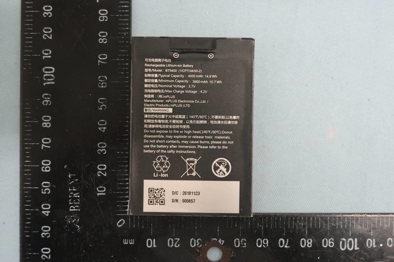
Q2QH31
May 17, 2020Mobile computers
Equipment Class
DSS - Part 15 Spread Spectrum Transmitter
Q2Q-EBS40
Apr 27, 2015ESL Base station
Equipment Class
DTS - Digital Transmission System