Q2XTSL315Keyfob transmitter
Four Star Marketing Group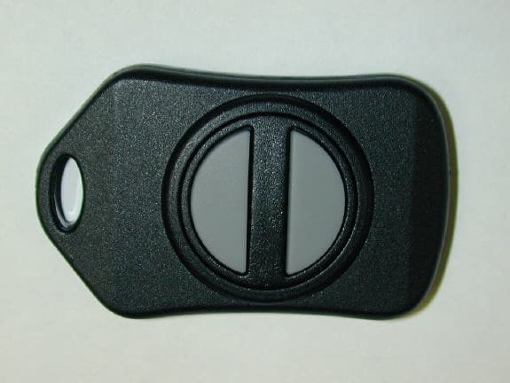
Click to zoom
Application Details
- Equipment Class
- DSC - Part 15 Security/Remote Control Transmitter
- Date of Grant
- Apr 10, 2003
- Application Purpose
- Original Equipment
- Date of Application
- Apr 10, 2003
- Equipment Note
- Keyfob transmitter
- Frequency Range
- 315.00000000 - 315.00000000
- Company
- Four Star Marketing Group
- Country
- United States
Documents & Files
Document Text
Text extracted from the exhibit documents filed with the FCC. Open a document above to read the original.
Users Manual
Distributed by Four Star Marketing – Andover, KS All Rights Reserved 315 Mhz Key Fob Transmitter Note: Button configuration may vary from illustration. FCC Warning *This device complies with Part 15 of the FCC rules. Operation is subject to the following two conditions: (1) this device may not cause harmful interference, and (2) this device must accept any interference received, including interference that may cause undesired operation. *Any changes or modifications not expressly approved by the manufacturer could void the user’s authority to operate the equipment. *This device transmits a radio frequency signal. The radio frequency signal should not be modified. Distributed by Four Star Marketing – Andover, KS All Rights Reserved Care and Maintenance 1) Do not immerse transmitter in water. If transmitter gets wet, dry immediately. 2) Avoid use of corrosive or abrasive materials that may damage plastic parts and corrode the electronic circuit. 3) Do not subject transmitter to extreme force, shock, temperature or humid conditions. This may result in malfunction, a shorter life span, or damage to batteries. 4) Do not tamper with internal components. This may result in improper operation or product failure. 5) See diagram below for battery replacement. Note: Replace only with #2032 coin cell battery Specifications Operating Voltage 3VDC Operating Temp -20 C to +70 C RF Frequency 315 Mhz Oscillator Crystal Tuned Dimensions: Height Width Depth 56.77mm (2.235”) 35.18mm (1.385”) 8.43 mm (0.332”) Weight: 0.4oz
External Photos
External Photos
ID Label/Location Info
The label is printed with permanent ink on a durable decal material. The dimension of the label is 1” x 1”. FCC ID.: Q2XTSL315
Internal Photos
Internal Photos Internal Component Side with Battery Holder Internal Keypad Side View Internal Component Side View without Battery Holder
Operational Description
Technical Description The key fob transmitter circuit primarily consists of a single IC component which combines an 8-bit EPROM-based CMOS microcontroller with a UHF ASK transmitter. The transmit portion of the IC is a fully integrated UHF ASK transmitter consisting of a crystal oscillator, a phaselocked loop (PLL), a single channel open-collector differential-output Power Amplifier (PA), and mode control logic. External components consist of bypass capacitors, a crystal, and a PLL loop filter. There are no internal electrical connections between the microcontroller and the transmitter. The microcontroller portion of the IC utilizes an internal 4Mhz RC oscillator that is independent from the transmitter crystal oscillator. The output frequency of 315Mhz is fixed and set by an external reference crystal of 9.8438Mhz. When activated, the circuit broadcasts a repeating 13-bit Manchester (50% duty cycle) pulse consisting of a Start bit, an 8-Bit Address and a 4-bit Data code.
Test Report
Nemko Test Report: 3L0043RUS1 Applicant: Four Star Marketing Equipment Under Test: 315 MHz Keyfob Transmitter (E.U.T.) In Accordance With: FCC Part 15, Subpart C For Low Power Transmitters Operating Periodically In The Band 40.66 - 40.77 MHz And Above 70 MHz Tested By: Nemko Dallas, Inc. 802 N. Kealy Lewisville, TX 75057-3136 Authorized By: Tom Tidwell, Frontline Manager Date: 3/7/03 Total Number of Pages: 20 Nemko Dallas, Inc. FCC PART 15, SUBPART C LOW POWER TRANSMITTERS EQUIPMENT: 315 MHz Keyfob Transmitter PROJECT NO.: 3L0043RUS1 Page 2 of 20 TABLE OF CONTENTS Section 1. Summary of Test Results...................................................................................3 Section 2. Equipment Under Test (E.U.T.)........................................................................5 Section 3. Equipment Configuration..................................................................................7 Section 4. Transmission Requirements...............................................................................8 Section 5. Radiated Emissions.........................................................................................10 Section 6. Occupied Bandwidth.......................................................................................15 Section 7. Block Diagrams...............................................................................................17 Section 8. Test Equipment List........................................................................................20 Nemko Dallas, Inc. FCC PART 15, SUBPART C LOW POWER TRANSMITTERS EQUIPMENT: 315 MHz Keyfob Transmitter PROJECT NO.: 3L0043RUS1 Page 3 of 20 Section 1. Summary of Test Results Manufacturer: Four Star Marketing Model No.: 315 MHz Keyfob Transmitter Serial No.: None General: All measurements are traceable to national standards. These tests were conducted on a sample of the equipment for the purpose of demonstrating compliance with Part 15, Subpart C, Paragraph 15.231. All tests were conducted using measurement procedure ANSI C63.4-1992. Radiated emissions are made on an open area test site. A description of the test facility is on file with the FCC. New Submission Production Unit Class II Permissive Change Pre-Production Unit THIS TEST REPORT RELATES ONLY TO THE ITEM(S) TESTED. THE FOLLOWING DEVIATIONS FROM, ADDITIONS TO, OR EXCLUSIONS FROM THE TEST SPECIFICATIONS HAVE BEEN MADE. None NVLAP LAB CODE: 100426-0 Nemko Dallas Inc. authorizes the above named company to reproduce this report provided it is reproduced in its entirety and for use by the company’s employees only. Any use which a third party makes of this report, or any reliance on or decisions to be made based on it, are the responsibility of such third parties. Nemko Dallas Inc. accepts no responsibility for damages, if any, suffered by any third party as a result of decisions made or actions based on this report. This report applies only to the items tested. Nemko Dallas, Inc. FCC PART 15, SUBPART C LOW POWER TRANSMITTERS EQUIPMENT: 315 MHz Keyfob Transmitter PROJECT NO.: 3L0043RUS1 Page 4 of 20 Summary Of Test Data Name of Test Paragraph No. Results Transmission Requirements 15.231(a) Complies Radiated Emissions 15.231(b) Complies Occupied Bandwidth 15.231(c) Complies Frequency Tolerance 15.231(d) N/A Alternate Field Strength Requirements 15.231(e) N/A Powerline Conducted Emissions 15.207 N/A Footnotes: 1) The device does not operate within the frequency band 40.66-40.70 MHz. 2) The device does not operate periodically. 3) The device is battery powered. Nemko Dallas, Inc. FCC PART 15, SUBPART C LOW POWER TRANSMITTERS EQUIPMENT: 315 MHz Keyfob Transmitter PROJECT NO.: 3L0043RUS1 Page 5 of 20 Section 2. Equipment Under Test (E.U.T.) General Equipment Information Frequency Range: 315 MHz Operating Frequency(ies) of Sample: 315 MHz Type of Emission: Digital Supply Power Requirement: 3 Volt battery Duty Cycle Correction Factor: -21.8 dB Description of E.U.T. The device is a keyfob transmitter used to turn on a lighting device. Modifications Incorporated in E.U.T. The EUT has not been modified from what is described by the brand name and unique type identification stated above. Nemko Dallas, Inc. FCC PART 15, SUBPART C LOW POWER TRANSMITTERS EQUIPMENT: 315 MHz Keyfob Transmitter PROJECT NO.: 3L0043RUS1 Page 6 of 20 Justification The E.U.T. was configured for testing as per typical installation. The following combinations were investigated to establish worst case configuration: (1) Lying flat (Worst case) (2) Upright (3) On edge. Exercise Mode The E.U.T. exercise mode used during radiated and conducted testing was designed to exercise the various system components in a manner similar to typical use. Exercise mode: (1) Tx on Nemko Dallas, Inc. FCC PART 15, SUBPART C LOW POWER TRANSMITTERS EQUIPMENT: 315 MHz Keyfob Transmitter PROJECT NO.: 3L0043RUS1 Page 7 of 20 Section 3. Equipment Configuration Configuration of the Equipment Under Test (E.U.T) Nemko Dallas, Inc. FCC PART 15, SUBPART C LOW POWER TRANSMITTERS EQUIPMENT: 315 MHz Keyfob Transmitter PROJECT NO.: 3L0043RUS1 Page 8 of 20 Section 4. Transmission Requirements NAME OF TEST: Transmission Requirements PARA. NO.: 15.231(a) TESTED BY: David Light DATE: 4/2/03 Minimum Standard: 15.231(a) Continuous transmissions such as voice, video or data transmissions are not permitted. 15.231(a)(1) A manually operated transmitter shall employ a switch that will automatically deactivate the transmitter within not more than 5 seconds after being released. 15.231(a)(2) A transmitter activated automatically shall cease transmission within 5 seconds of activation. 15.231(a)(3) Periodic transmissions at regular pre- determined intervals are not permitted. However polling or supervisory transmissions to determine system integrity of transmitters used in security or safety applications are allowed if the periodic rate of transmission does not exceed one transmission of not more than one second duration per hour…
Text truncated - open the document above for the full version.
Contact Information
Applicant
Kevin Ferris(General Partner)
Technical Contact
Nemko DallasTom Tidwell
[email protected]972-436-9600
802 N. Kealy · Lewisville, Texas · United States
Non-Technical Contact
Nemko DallasSusan Griffith
[email protected]972-436-9600
Test Firm
Nemko Dallas, Inc.Michael Cantwell
Technical Specifications
| # | Rule Parts | Frequency Range | Power Output |
|---|---|---|---|
| 1 | 15.231 | 315 MHz - 315 MHz | - |