Text extracted from the exhibit documents filed with the FCC. Open a document above to read the original.
User Manual HA-200 Hearing Enhancer BIOSOUNDLAB CO., LTD. Contact Us ※ Please contact the place of purchase for returning the product. ■Please call our office first in case of a product failure. ■For after-sales services, please send the product to the following address. BIOSOUNDLAB CO., LTD. www.biosoundlab.com Address : Suite 311, 312 Bi z Center, Skn TechnoPark 190-1 Sangdaewon-dong, Jungwon-gu, Seongnam-si, Gyeonggi-do, Zip-code : 462-721, South Korea TEL : +82-31- 776 -0636 FAX : +82-31- 776 -0639 Contents Safety instructions Product characteristics Features and Accessories Product descriptions – Blue tooth Hearing Enhancer Power on/off – Bluetooth Hearing Enhancer LED state display Basic Operation – Bluet ooth Hearing Enhancer TV reception Pairing of Units (Pairing ; TV Reception Mode) Pairing with your Mobile Phone Battery charging Use of battery Introduction of Bluetooth FAQ Product specifications Warranty Contact Us Warranty This product has passed the company's own quality control and thorough inspection. While using it, if any manufacturing defect is found or it breaks down, contact the place of purchase or our head offi ce for after-sales services. Product Name Bluetooth Hearing Enhancer Serial No. Purchase date Date of manufacture Place of purchasing Selling price < After Service Regulations > 1. The warranty period of this product is one year from the date of purchase. 2. Any failure which occurs under normal use during the warranty period shall be repaired free of charge. 3. In the following cases, repair costs shall be charged even during the warranty period. (1) Failures and damage which are caused by user's negligent handling or an improper use of the product. (2) Failures and damage which are caused by any product repair, remodeling, disassembly, and cleaning at user's own discretion. (3) Failures which are caused by natural disa sters such as fire, earthquake, flood, or lightning. (4) Failures and damage which are caused by poor storage such as falling, impact, pressurizing, dust, sand, or flooding. (5) Failures and damage which are caused by careless storage (hot and humid places or intense cold). (6) Failures and damage which are caused by using consumables or components that are not genuine products. (7) In case it is impossible to check if the used product is a genuine one (In case the serial number plate attached at the bottom of the product is damaged). 4. The warranty regulations on the repair, repl acement, and refund of the product shall be in accordance with th e customer injury compensation ru le of the notification of the Ministry of Finance and Economy. 5. The holding period of key components is 3 years. The design, specification and user's manual of this product are subject to change without notice for performance improvement. Product Specifications Names of devices Bluetooth Hearing Enhancer Supported Bluetooth profiles Headset Profile V1.2 Frequency range 2402 ~ 2480 MHz Size 55(L) X 19(W) X 34(H)mm Weight 11g Bluetooth specification Bluetooth V2.1( Power Class 2) Wireless range maximum 10m Continuous call time About 4 Hours Call waiting time About 100 Hours Battery Lithium Polymer Battery / DC 3.7V * The wireless range is subject to ch ange depending on working environment. Safety Instructions 1. Do not drop the product. If you dropped it, check its sound. If a defect is found, ask for a repair immediately. 2. Do not get the product wet. 3. Conduct an inspection periodically. 4. Be careful when you wear the product because you may strain your ears due to some feedback sound if you wear it when it is not completely turned off. 5. It is prohibited from wearing it if you have a wound in your external auditory meatus, or an inflammation in your middle year, or if there is anything wrong with your eardrum. 6. In case you have an inflammation in your external auditory meatus, wearing it may cause serious side effects such as hearing loss. Therefore, consult a medical specialist in such a case. 7. If you need the function of TV recepti on, use the transmitter supplied together with the product. 8. The function of mobile phone can be used only with the type of phones compatible with Bluetooth 2.1. Product Characteristics 1.With its Bluetooth function, it is possi ble to have clear telephone conversations by linking it with a mobile phone. 2. Users can adjust the volume to a suita ble sound level according to their hearing ability. 3. It is designed to hear dialogues clear ly and naturally by reducing noises greatly in the surroundings. 3. If it is linked to a mobile phone for telephone conversations, you can hear voices very clearly. FAQ Are there any factors which obstruct telephone conversations? As devices such as wireless telephones or wireless network devices may cause noises, thus destructing telephone conversations, if possible, it is recommended to use the product in areas which are far away from such devices that use or create radio waves. Does the product have any effect on electronic products in a car, a radio, or a computer? The product generates less power than an ordinary mobile phone and complies with the International Bluetooth Standard. Therefore, it does not exert any effect on standard consumer class electronic products. Is it possible for other Bluetooth users to hear my telephone conversations? If a Bluetooth mobile phone is registered with the main unit, the connection is made only between two devices. And as the frequency power of wireless Bluetooth signal is lower than that of ordinary mobile phones, it is not easy for a third person to trace telephone conversations. During telephone conversations, it makes a noise. Adjust the volume or move to use it in other areas. How is the product maintained? Clean the product lightly with a clean and soft cloth. Battery charging is not completed. The product and the battery charger may not be properly connected. Disconnect them and connect them again to re-charge it. Introduction of Bluetooth 1…
Text truncated - open the document above for the full version.
FCC, Request for non-disclosure Date: September 12, 2012 Page 1 of 1 BioSound Lab Co., Ltd. (Sangdaewon-dong, Sunil Technopia 907-908ho) Dunchon-daero 555, Jungwon-gu, Seongnam-si, Gyeonggi-do, South Korea Subject: Request for confidentiality FCC ID: Q32HA200 Reference number: Dear FCC TCB, Persuant to 47 CFR Section 0.459(a) & (b), <BioSound Lab Co., Ltd.> hereby requests non-disclosure and confidential treatment of the following materials submitted in support of FCC certification application for FCC ID: (Q32HA200) ☑ Bill(s) of Material ☑ Block Diagrams ☑ Operational Description ☑ Schematic Diagrams Above materials contain secrets, proprietary and technical information, which would customarily be quarded from competitors under 47 CFR, section 0.457(d)(2). Disclosure or publication or any portion of this company confidential material to other parties could cause substantial competitive harm and provide unjustified benefits for competitors. <BioSound Lab Co., Ltd.> understands that pursuant to 47 CFR section 0.457(d)(1)(ii) disclosure of the applicant and all accompanying documentation will not be made before the date of the grant. <Date>September 12, 2012 <City> Seongnam <Name and signature of applicant> Cheonjumg, Park / President
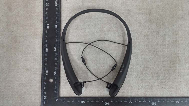
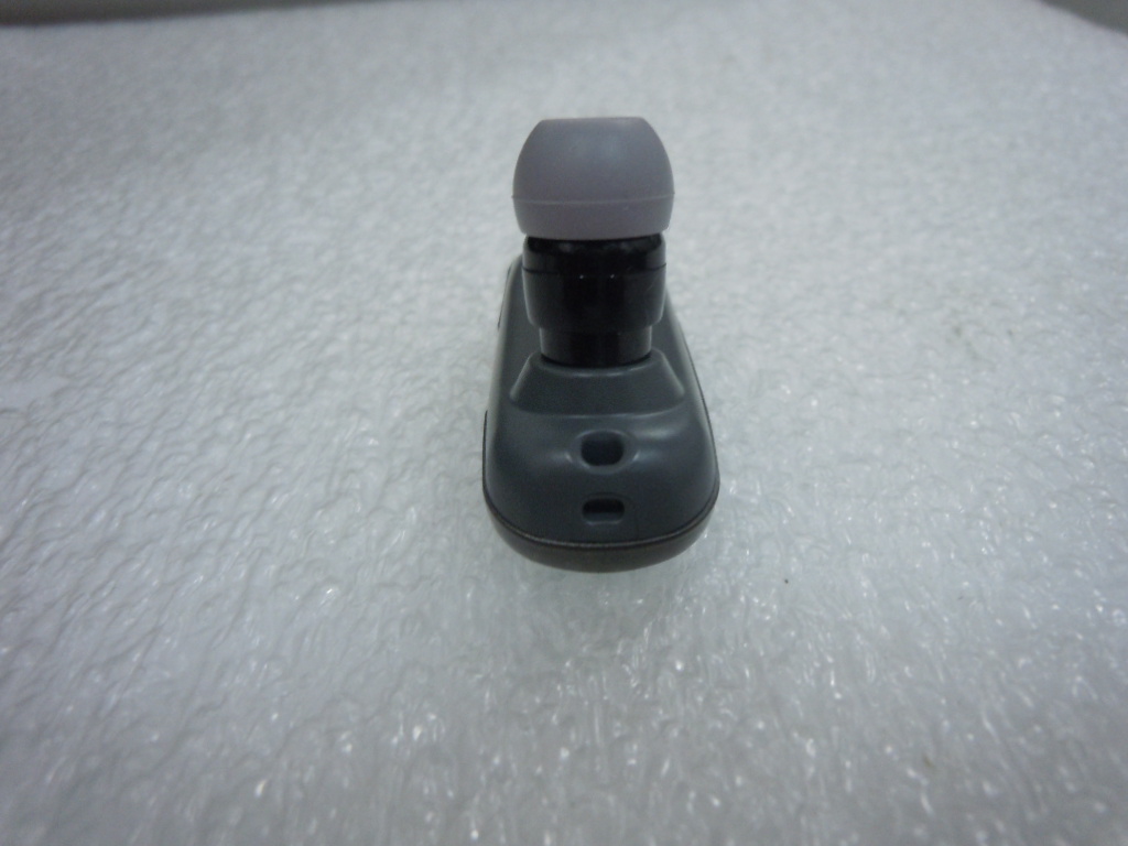
External photos of EUT Front view of EUT Rear view of EUT Top view of EUT Bottom view of EUT Side view of EUT
Label Information 1. Label Location Label position 2. Label Drawing
Internal photos of EUT Antenna view of EUT Internal view of EUT Chip Antenna Top view of Main PCB Bottom view of Main PCB
Dielectric Chip Antenna - Application Frequency Band[MHz] Bluetooth2400 ~ 2485 WiFi / Zigbee2400 ~ 2485 S-DMB2630 ~ 2655 Wibro 2300 ~ 2390 band1 : 2300 ~ 2327 band2 : 2331.5 ~ 2358.5 bnad3 : 2363 ~ 2390 Original Design Chip Antenna Data Sheet - P/N : SDBTPTR3015 - Dielectric Chip Antenna ■SDBTPTR3015 Dimension ParameterLWTABCDE Value[mm] 3.0 ±0.1 1.5 ±0.1 1.2 ±0.1 1.00.550.41.10.65 Unless Specified tolerances are ± 0.05 mm Dielectric Chip Antenna ■AutoCAD Drawing of Reference PCB Design for SDBTPTR3015 Product 41 2 3 Dielectric Chip Antenna ■PCB Drawing Top View Case #1 <Default> 12 3 4 Case #2 12 3 4 Case #3 12 3 4 Case #4 12 3 4 Bottom View <Equivalent Circuit> Dielectric Chip Antenna ■Matching Value Band (MHz) Matching Value (Default) Bluetooth / WiFi / Zigbee (2400 ~ 2485) Connector N/C Ant. 100pF 1.8pF 100 pF N/C S-DMB ( 2630 ~ 2655) Connector N/C Ant. 100pF 1.0nH 100 pF N/C Wibro (2300 ~ 2390) band1:2300~2327 band2:2331.5~2358.5 bnad3:2363~2390 Connector N/C Ant. 100pF 2.0pF 100 pF N/C Dielectric Chip Antenna - 3D Passive Gain For Bluetooth / WiFi / Zigbee ■Test Result for Ver 0.0 SWR & Smith chart3D Peak [dBi] Average [dBi] Efficiency [%] 2400MHz1.96-0.9780.18 2425MHz1.99-0.6685.92 2445MHz1.74-0.8582.42 2465MHz1.27-1.2575.12 2485MHz0.86-1.6468.59 ■Radiation PatternVer 0.0 3D Passive Dielectric Chip Antenna - 3D Passive Gain For S-DMB ■Test Result for Ver 0.0 SWR & Smith chart3D Peak [dBi] Average [dBi] Efficiency [%] 2627MHz4.33-0.3891.80 2642MHz4.67-0.3692.06 2657MHz4.71-0.5688.02 ■Radiation PatternVer 0.0 3D Passive Dielectric Chip Antenna - 3D Passive Gain For Wibro ■Test Result for Ver 0.0 SWR & Smith chart3D Peak [dBi] Average [dBi] Efficiency [%] 2300MHz2.51-0.8482.52 2322.5MHz 2.68-0.7883.71 2345MHz3.15-0.4590.20 2367.5MHz 3.02-0.7883.76 2390MHz3.09-0.8682.12 ■Radiation PatternVer 0.0 3D Passive
1. Information 1) Company Name : BioSound Lab Co., Ltd. 2) Product Name : Hearing Enhancer 3) Model Name : HA200 4) FCC ID : Q32HA200 2. RF Exposure According to §KDB 447 498 D01 V04 4(c)(iii), (1) Hand SAR is required for hand-held and hand-operated devices with output power > 1000[f(GHz)]-0.5 mW that are designed with the hand operating closer than 5cm from the antenna during normal use. (2) Extremity SAR is required for wrist, feet or ankle worn dev- -ices. (3)Body SAR is required for hand-held and hand-operated or wrist, feet and ankle worn devices that operate closer than 5cm to the body and the output power is > 300[f(GHz)]-0.5 mW. 2.1 Technical Information: Antenna Type: Chip antenna Antenna Gain: 1.99dBi Maximum Transmitter Conducted Power: -4.02dBm, 0.39mW Maximum System EIRP: 0.09dBm, 1.02mW 2.2 RF Exposure Compliance Justification: 1) Hand SAR Model S1 is exempt from SAR based on the output power (higher of conducted or EIRP) being < 1000*[f(GHz)]^(-0.5)mW. SAR threshold and maximum equipment EIRP calculations are provided below. MPE calculations are also provided for satisfying mobile RF exposure conditions. SAR Threshold = 1000*[2.441]^(-0.5)mW = 640.053mW Maximum Equipment EIRP = 1.02mW 2) Body SAR Model S1 is exempt from SAR based on the output power (higher of conducted or EIRP) being < 300*[f(GHz)]^(-0.5)mW. SAR threshold and maximum equipment EIRP calculations are provided below. MPE calculations are also provided for satisfying mobile RF exposure conditions. SAR Threshold = 300*[2.441]^(-0.5)mW = 192.016mW Maximum Equipment EIRP = 1.02mW Completed By : Cheonjumg, Park Date : September 12, 2012 RF EXPOSURE
FCC TEST REPORT UCS Co., Ltd. #702, Megavalley, 799 Kwanyang-dong, Dongan-gu, Anyang-city, Kyunggi-do, 431-767, Korea Tel : 82-31-420-5680/Fax :82-31-420-5685, Open Site : 82-31-355-2666 Report Number: UCSFR-1209-007 FCC ID : Q32HA200 UCS-QP-20-03-80(Rev.0) Page 3 / 32 Contents 1. Applicant Information Page 4 2. Test Result Certification Page 4 3. EUT Information Page 4 4. Laboratory Information Page 5 5. Test Methodology Page 6 6. Limite And Result Page 7 7.Test Equipment Used For Test Page 31 8. EUT Photographs Page 32 Report Number: UCSFR-1209-007 FCC ID : Q32HA200 UCS-QP-20-03-80(Rev.0) Page 4 / 32 1. Applicant Information Applicant Name : BioSound Lab Co., Ltd. Address : (Sangdaewon-dong, Sunil Technopia 907-908ho) Dunchon-daero 555, Jungwon-gu Seongnam-si Gyeonggi-do, South Korea Manufacturer : BioSound Lab Co., Ltd. Country of Origin : South Korea 2. Test Result Certification 2.1 Applicable standards Standard Test Item CFR 47 Section Result ETSI EN 300 328 (V 1.7.1:2006) Antenna Requirement 15.203, 15.247(b)(4) PASS 20dB Bandwidth 15.247(a)(1) PASS Maximum Peak Output Power 15.247(b)(1) PASS Carrier Frequency Separation 15.247(a)(1) PASS Number of Hopping Channels 15.247(a)(1)(iii) PASS Time of Occupancy (Dwell Time) 15.247(a) PA S S Spurious Emission, Band Edge, and Restricted bands 15.247(d), 15.209 PA S S AC Power Line Conducted Emissions 15.247(a) PA S S Receiver Spurious Emissions - PA S S RF Exposure 15.247(i), 1.1307(b)(1) PA S S 3. EUT Information 3.1 RF specification Product name Hearing Enhancer Model name HA200 Power source DC 3.7 V Output Power 0.00039 Ferquency range 2402 MHz ~ 2480 MHz Number of channels 79 CH Modulation Technique FHSS(GFSK) Antenna specification 1.99 dBi gain (Max) Weight 53(L)mmX20(W)mmX12(H)mm Dimension 10g Under Report Number: UCSFR-1209-007 FCC ID : Q32HA200 UCS-QP-20-03-80(Rev.0) Page 5 / 32 4. Laboratory Information 4.1. General UCS Co., Ltd. established 1999 as the International agreed upon laboratory(CBTL, KOLAS) for Standard. Internally, UCS Co., Ltd. is the designated test laboratory from Radio Research Laboratory of Korea Communications Commission and Korea Food & Drug Administration. Based on its extensive experience and expertise, UCS Co., Ltd. is the Global test laboratory that has best professionalism in this field. 4.2. Test Site - UCS Co., Ltd. (Universal Certification Solution) - FCC Registration Number : 803225 - This test site is in compliance with ISO/IEC 17025 for general requirements for the competence of testing and calibration laboratories. 4.3 Location UCS Co., Ltd. - #702, Anyang Megavalley799, Gwanyang2-dong, Dongan-gu, Anyang-si, Gyeonggi-do, 431-767, Korea ER Center - #476-4, Hwalcho-dong, Hwaseong-si, Gyeonggi-do, 445-150, Korea Report Number: UCSFR-1209-007 FCC ID : Q32HA200 UCS-QP-20-03-80(Rev.0) Page 6 / 32 5. Test Methodology 5.1 Description of test modes - The EUT had been tested under the operating condition. - There are three channels have been tested as following: - Channel Low and Channel High with higher data rate were chosen for full testing. Channel Frequency (MHz) Low 2402 Middle 2441 High 2480 - The measurements were taken in continuous transmitting mode using the TEST MODE. - For controlling the EUT as TEST MODE, the test program and the cable assembly were provided by the applicant. [System Block Diagram of Test Configuration] 5.2. Setup of equipment under test 5.2.1. Description of support units - The EUT has been tested as an independent unit along with the following necessary Accessories or support units, which are adopted to form a representative test configuration. No Equipment Manufacturer Model S/N 1 Notebook** HP PSMDCK-06L001- 2 TEST JIG** BioSound Lab Co., Ltd. - - Notes: ** For control of the RF module via USB interface in the EUT. For radiated spurious emission measurements, the EUT was tested as stand-alone equipment without TEST JIG, setting the EUT to TEST MODE. 5.2.2. Type of Used Cables No START END CABLE NAME I/O PORT NAME I/O PORT LENGTH(m) SHIELDED 1 Notebook USB TEST JIG RS-232 1.0 Shielded - - - - - - - Notebook JIG EUT USB Spectrum Analyzer Report Number: UCSFR-1209-007 FCC ID : Q32HA200 UCS-QP-20-03-80(Rev.0) Page 7 / 32 6. Limite And Result 6.1. Antenna requirement 6.1.1. Regulation According to §15.203, an intentional radiator shall be designed to ensure that no antenna other than that furnished by the responsible party shall be used with the device. The use of a permanently attached antenna or of an antenna that uses a unique coupling to the intentional radiator shall be considered sufficient to comply with the provisions of this Section. The manufacturer may design the unit so that a broken antenna can be replaced by the user, but the use of a standard antenna jack or electrical connector is prohibited. And according to §15.247(b)(4), the conducted output power limit specified in paragraph (b) of this section is based on the use of antennas with directional gains that do not exceed 6 dBi. Except as shown in paragraph (c) of this section, if transmitting antennas of directional gain greater than 6 dBi are used, the conducted output power from the intentional radiator shall be reduced below the stated values in paragraphs (b)(1), (b)(2), and (b)(3) of this section, as appropriate, by the amount in dB that the directional gain of the antenna exceeds 6 dBi. 6.1.2. Results : PASS The transmitter has an integral Chip antenna. The directional gain of the antenna is 1.99 dBi. Report Number: UCSFR-1209-007 FCC ID : Q32HA200 UCS-QP-20-03-80(Rev.0) Page 8 / 32 6.2. 20dB Bandwidth 6.2.1. Regulation According to §15.247(a)(1), frequency hopping systems shall have hopping channel carrier frequencies separated by a minimum of 25 kHz or the 20 dB bandwidth of the hopping channel, whichever is greater. Alternatively, frequency hopping systems operating in the 2400-2483.5 MHz band may have hopping channel carrier frequencies that are separated by 25 kHz or two- thirds of the 20 dB bandwidth of…
Text truncated - open the document above for the full version.
| # | Rule Parts | Frequency Range | Power Output |
|---|---|---|---|
| 1 | 15C | 2.40 GHz - 2.48 GHz | 1.00 mW |

Smart(Hearing Aid)
Equipment Class
DSS - Part 15 Spread Spectrum Transmitter