Q3USBA-2000Security Transmitter
Securitas America, Inc.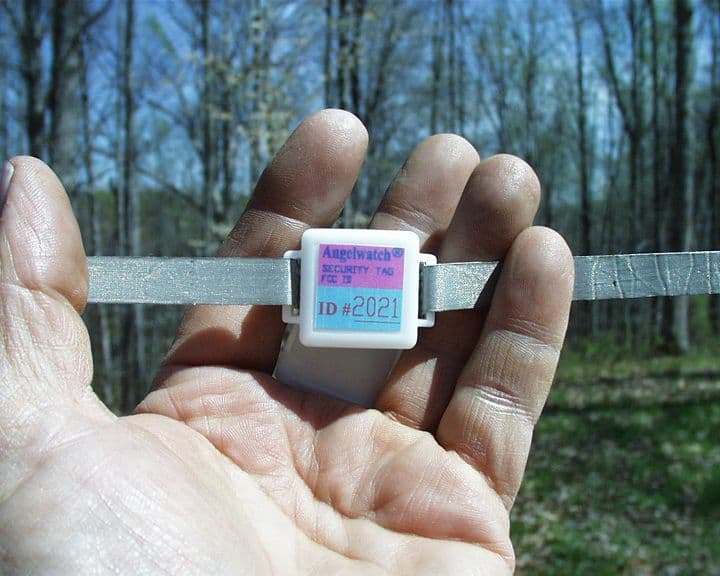
Click to zoom
Application Details
- Equipment Class
- DSC - Part 15 Security/Remote Control Transmitter
- Date of Grant
- Jun 10, 2003
- Application Purpose
- Original Equipment
- Date of Application
- Jun 10, 2003
- Equipment Note
- Security Transmitter
- Frequency Range
- 417.80000000 - 418.20000000
- Company
- Securitas America, Inc.
- Country
- United States
Documents & Files
Document Text
Text extracted from the exhibit documents filed with the FCC. Open a document above to read the original.
Users Manual
SECURITAS AMERICA, INC. ANGELWATCH TM INFANT PROTECTION SYSTEM OPERATION MANUAL © Copyright 2001 Securitas America, Inc. All rights reserved Securitas America, Inc. 552 NW 77 th Street Boca Raton, FL 33487 Phone: 561-989-3608 Fax: 561-997-6923 09-12-02 Revision 3.3 TABLE OF CONTENTS Cover ..................................................................... i Table of Contents ....................................................... ii 1. INTRODUCTION ................................................................... .. 1 Overview of System ............................................................ ...... 1 Equipment ........................................................................ . 2 Starting the System ............................................................... ... 3 System Display ................................................................. . ... 3 2. MAINTENANCE COMMANDS .................................................. 4 File ........................................................................ . ............ 5 Set System Parameters .......................................................... ... 6 Edit Maintenance Passwords.................................................... ... 7 Edit Administrator Passwords.................................................... ... 8 Edit Receiver List ................................................................... 9 Receiver Test ......................................................................... 9 Edit Remote List ................................................................... 11 Remote Test ......................................................................... 12 3. ADMINISTRATOR COMMANDS ............................................... 14 Edit Passwords ........................................................................ 14 Reports ................................................................................. 15 Backup ................................................................................. 15 4. SUPERVISOR COMMANDS ..................................................... 16 Lock Doors ............................................................................. 16 Unlock Doors ......................................................................... 16 Clear All Alarms ...................................................................... 17 5. USER COMMANDS................................................................. 17 Login New Patient .................................................................... 18 Excuse Patient ......................................................................... 19 Re-Enter Patient ............................................................ ......... 20 Discharge Patient ..................................................................... 21 6. THE ANGELWATCH SMARTBAND ANKLET................................ 23 7. THE ANGELWATCH REUSABLE TAG......................................... 24 ii 1. INTRODUCTION Overview of System The PC Based Angelwatch™ Infant Protection System is designed to monitor the location of infants who are wearing a special Angelwatch SmartBand anklet. This anklet is an active transmitter that allows the system to continuously monitor the presence of the infant and the status of the anklet band itself. The SmartBand anklet (Model # SBA-1000) transmits its identification and status. These transmissions are detected by receivers located throughout the area to be monitored. Three types of receivers are used to provide full coverage. The receivers are similar, the difference is what they detect and what they do afterwards. The Internal locating receivers (Model # INR-1000) are used to cover the entire area to be secured. The Internal locating receivers are designed to send an alarm whenever the signal from the anklet is lost. This indicates that the baby has been moved outside the coverage area or that the anklet has been disabled. The Internal locating receivers also detect the signal from a anklet that has been broken or cut so the system can activate the appropriate alarm. The Exit receiver (Model # EXR-1000) is a receiver located at any exit from the coverage area. Whenever an Exit receiver detects the signal from an anklet, an alarm is set indicating that the baby is being taken out the indicated entrance. This alarm can be used to activate a camera. Because of the area covered and the fact that the system activates an alarm whenever the Exit receiver detects an anklet, it is not recommended for use as an exit control. The Locking receiver (also Model # EXR-1000) is a receiver specifically configured to control exits. When this receiver detects an anklet, it activates its output but does not set an alarm. This allows the receiver to be used in high traffic areas to control an exit. The exit locks will be set whenever the receiver detects an anklet, but will not set an alarm in case the anklet is still in an allowed area. It is best to back these receivers up with Exit receivers outside the exits so that if an infant is taken through the exit, an alarm will then be set. By themselves, these three types of receiver provide a great deal of security. How- ever, someone trying to abduct a baby may realize that the anklet is part of the security system and try to remove it. If the anklet is cut, it instantly sends out a signal indicating it has been cut. This helps to ensure that the baby is constantly monitored. 1 Equipment A variety of equipment is used to make up an Angelwatch system. The equipment actually installed at a site will vary depending on the needs of that particular hospital. Workstations The Angelwatch system is based around a small computer running the system soft- ware. This computer is called the Master Workstation (Model # MWS-1000) and all the receivers and Remote Workstations are connected to it. The computer uses Microsoft Windows 2000 as an operating system. In addition, the computer is equipped with an Uninterruptib…
Text truncated - open the document above for the full version.
Block Diagram
ANTENNA C? VAL VAL R? 3V lithium PIC12LC509 CONTROLLER MICRO- SAW OSC. 418 MHz. TX5002 SECURITAS Q3USBA-2000 1 1 BLOCK DIAGRAM AB CD 4 321 D C B A 12 34 of SheetDrawn by Rev Number TitleSize A DateFilename
Cover Letter(s)
C:\DOCUME~1\doris\LOCALS~1\Temp\probonholdemail.doc TIMCO ENGINEERING INC. 849 NW State Road 45 Newberry, Florida 32669 http://www.timcoengr.com 888.472.2424 F 352.472.2030 email: [email protected] May 29, 2003 FCC SUBJECT: SECURITAS AMERICA, INC. - FCC ID: Q3USBA-2000 TYPOGRAPHICAL ERROR To whom it may concern: There is a typographical error on Page 5 of the Test Report. The bandwith pulse measurement is stated to be 2.5 ms wide. The bandwidth plot on Page 6 shows the correct bandwidth to be 260 usec. The 260 usec bandwidth was used correctly to calculate the Duty Cycle Correction Factor. Very truly yours, Frank DeNuzzo
Operational Description
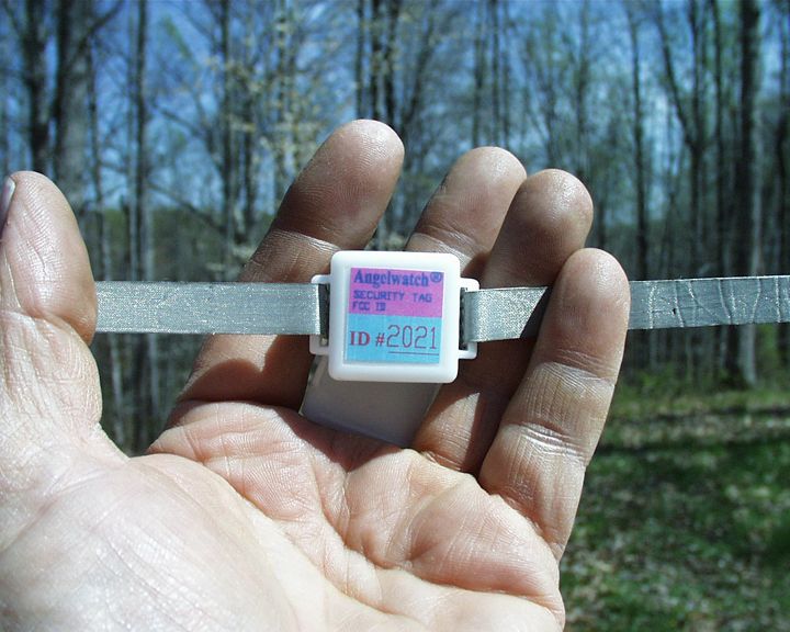
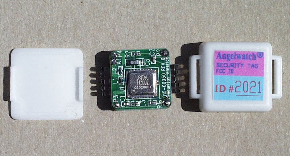
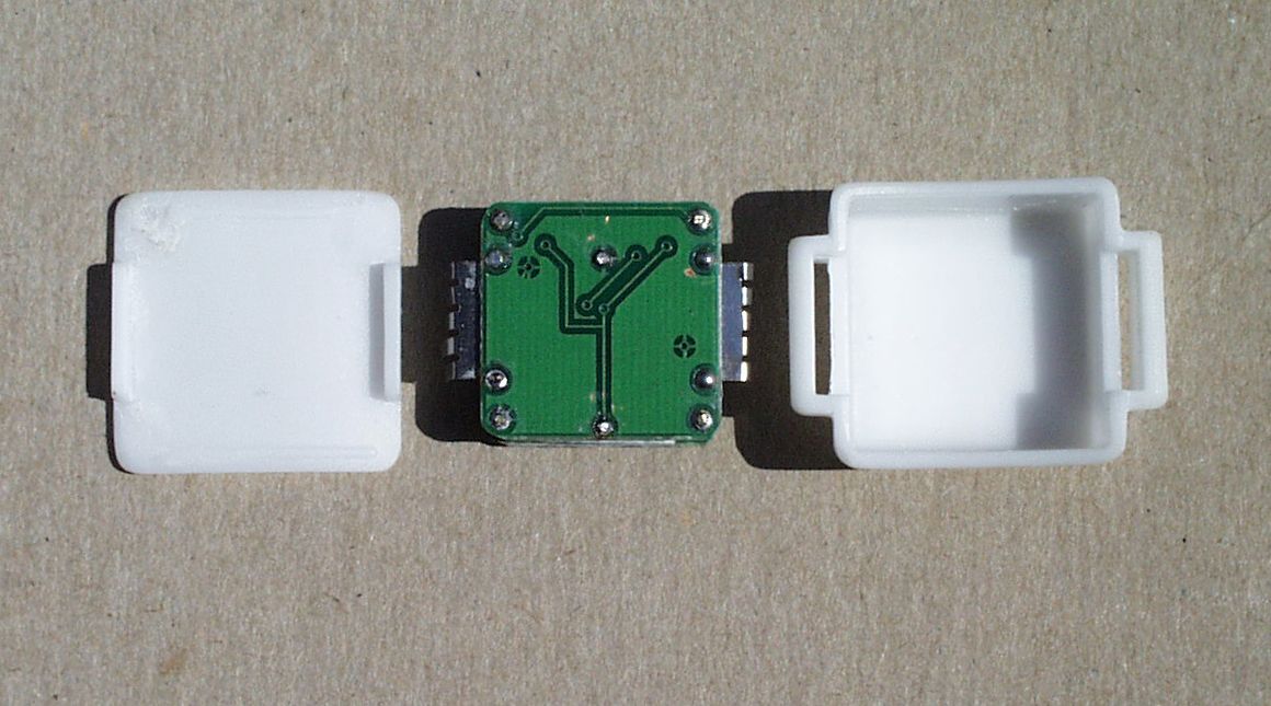
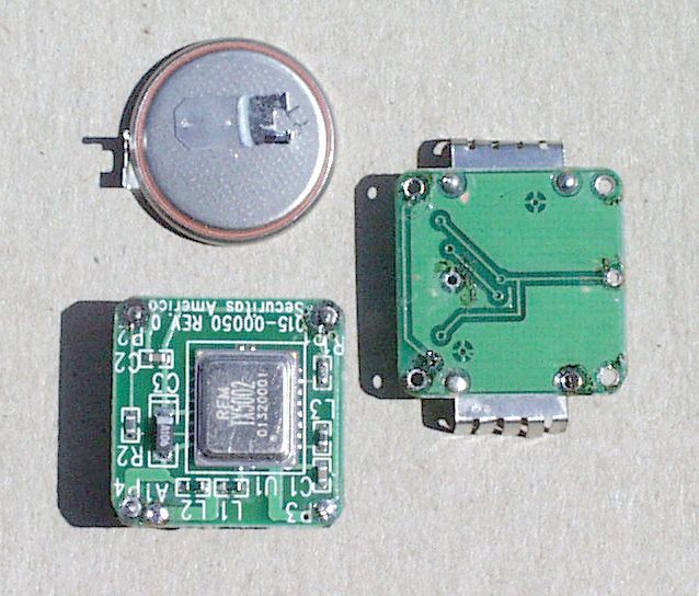
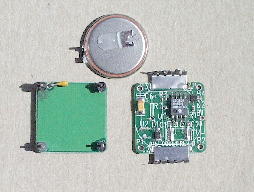
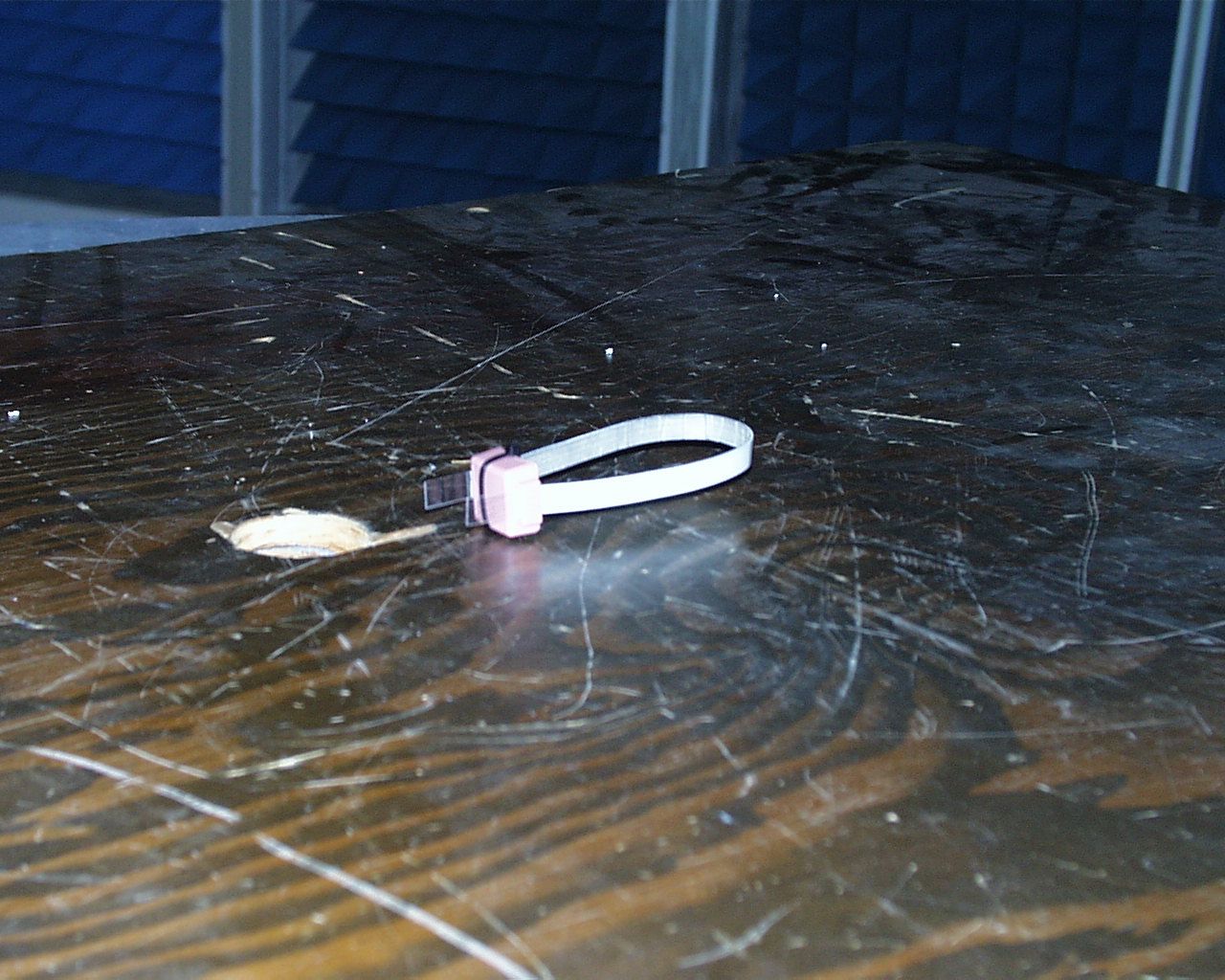
Circuit Description The Angelwatch reusable tag consists of two Printed Circuit Boards (PCB’s) connected by four conductive board standoff pins marked P1, P2, P3 and P4 on both PCB's. The bottom PCB is part # 015-00051. This board contains the Microcontroller IC, the metal spring fingers, and the battery. Referring to the schematic drawing, the battery is labeled B1. The microcontroller is U1. The spring finger contacts are J1 and J2. The spring finger contacts have prongs which grab the conductive strap used to attach the tag to arm or leg of the patient being tagged. When the strap bridges the gap from J1 to J2, the input pin GP1 on the microcontroller which is normally pulled low by resister R3, is pulled high. when the microcontroller senses that this input is pulled high for on uninterrupted minute, it signals the transmitter IC on the top PCB to transmit through the standoff pins P1a d P2. Resistors R! and R7 and diodes D1and D2 are to protect the circuit from Electrostatic Discharge (ESDP when the strap is touched. Capacitor C6 keeps the +3 volt DC battery output from dipping during transmission. The other two standoff pins P3 and P4 connect power and ground to the top PCB. The top PCB is part # 015-00050. This board contains the RFM 418.00 MHz Hybrid transmitter TX5002. Referring to the schematic drawing, this part is labeled U1 on the top PCB. The resistor R1, the TXMOD resistor, is used to adjust the output power. The resistor R2 is used to protect U1 from ESD. The output is terminated at inductors L1 and L2 and connected through C4 to the spring finger J1 on the bottom PCB. The transmission consists of two 31 millisecond pulse trains separated by a gap of approximately 200 milliseconds. See Figure 1. Each pulse train consists of 14 pulses, each pulse being 0.25 milliseconds wide, with a gap of approximately 2.1 milliseconds between pulses. The whole pulse train is approximately 31 milliseconds long. The transmission scheme used is On-Off Keyed. The transmitter outputs two of these 31 milliseconds pulse trains with a gap of approximately 200 milliseconds, then turns off for 10to 12 seconds. (2x 14 x 0.25 milliseconds = 7 milliseconds). The 14 pulses represent a digital ID code plus an alarm bit. The position of each pulse relative to the start bit determines its value. When the Strap is cut, this represents a possibly life threatening emergency, such as a baby being stolen from the maternity unit. The transmitter then transmits once every 2 seconds for 30 seconds, then goes back to normal spacing (once every10 to 12 seconds) for 10 minutes, then shuts down. Normal operation resumes when a new strap is applied. .
Test Report
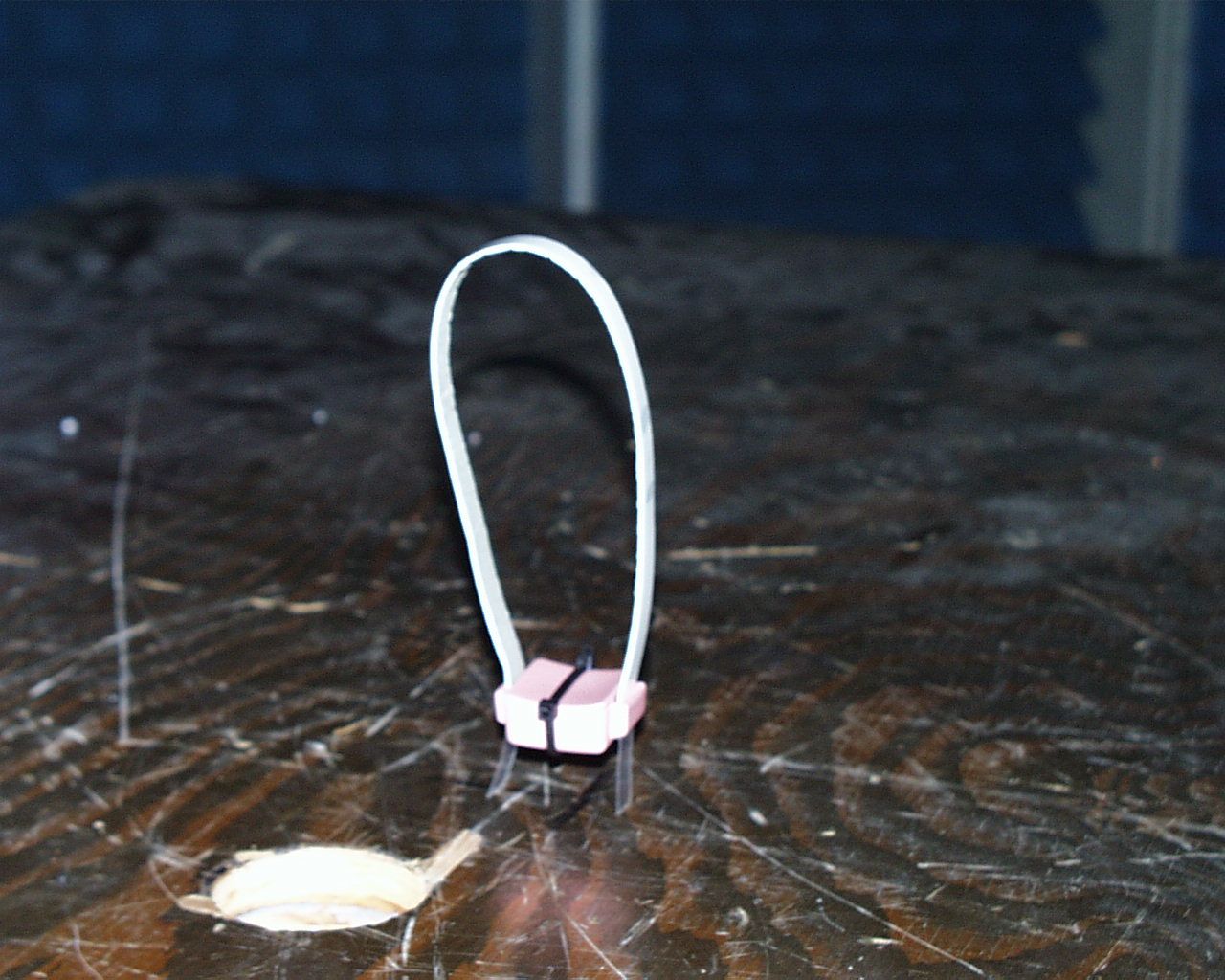
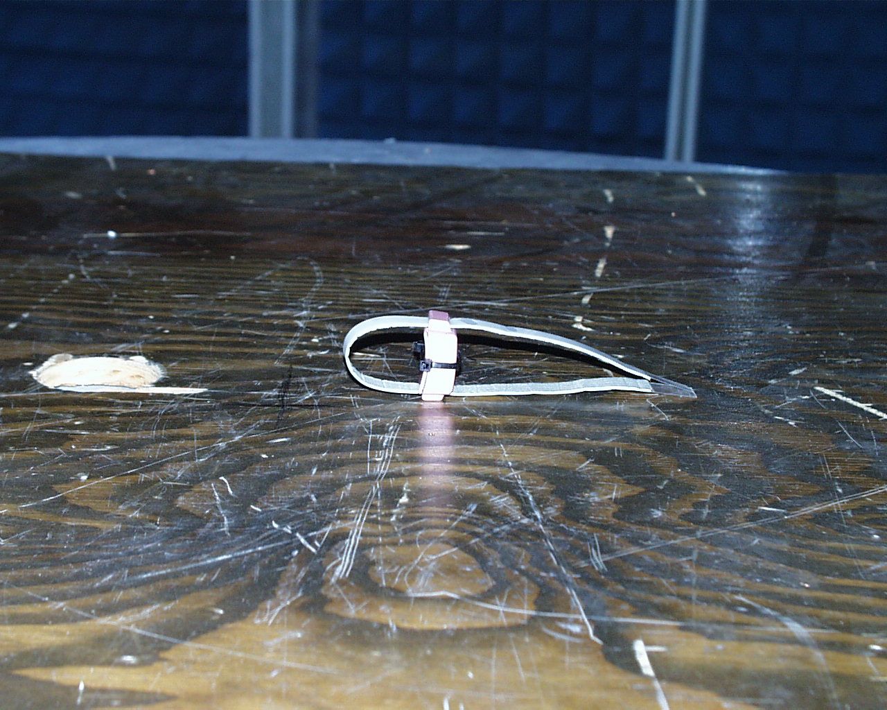
Q3USBA-2000 SECURITAS AMERICA Test Report of an Intentional Radiator for Certification under Part 15 of the FCC rules DUT: Alarm Transmitter FCC ID Q3USBA-2000 Section 15.231(e) Date: 14-April-2003 Manufacturer: Securitas America, Inc. 272 20 th Street North Jacksonville Beach, FL 32250 (561) 706-7716 Prepared by: Control Design & Testing, Inc. 6010 Red Fox Drive Spotsylvania, VA 22553 (540) 582-2826 1 Q3USBA-2000 SECURITAS AMERICA A. DEVICE UNDER TEST The product is a transmitter used as a security device to monitor the location of infant children in hospital environments. This device is designed to be attached to the infant’s body and is inactive until placed on the child. The product is designed to operate under the provisions of Part 15.231(e) of the FCC rules in the United States and RSS-210 in Canada. The device is self contained in a plastic enclosure and is powered by an internal 3 volt lithium coin cell. The frequency of operation is 418.00 MHz. nominal. The modulation mode is on/off keying using a proprietary pulse position scheme. In normal operation, this device is programmed to transmit two identification packets every 10 – 11 seconds. During an emergency condition, the device transmits two packets every 2 seconds. The test samples are in a prototype plastic enclosures. The FCC ID will be printed on the cover lable as shown in the external photographs. B. MEASUREMENT PROCEDURE: RADIATED EMISSIONS Radiated emissions testing of this device was conducted at the Carl T. Jones test facility located in Springfield, Virginia. FCC Site #90490 The field strength measurements were conducted according to the procedures set forth in ANSI C63.4 (1992). The device under test was placed on a rotating turntable 0.8 meters high, centered at 3 meters distant from the measurement antenna. Two sets of measurements were taken: 1) with the strap/antenna configured for maximum length and, 2) with the strap drawn into a tight circle. For each configuration, the device was placed in the center of the turntable and tested in two positions as shown in the test setup photographs. For the purpose of radiated emissions testing, one of the test samples was specially programmed to transmit a continuous pulse stream. The occupied bandwidth plot below (Plot 1) was captured using this signal. 2 Q3USBA-2000 SECURITAS AMERICA Plot 1 3 Q3USBA-2000 SECURITAS AMERICA The field strength measurements were taken using an HP8596E spectrum analyzer, an EMCO 3121C dipole set, an EMCO 3115 double ridge guide horn and an Avantek UJ210 preamp. The device was scanned from 30 MHz. to 5 GHz. and all emissions were noted. In this case, the only emissions detected were those harmonically related to the fundamental transmit frequency. At each detected emission frequency, the device was measured by rotating the turntable and adjusting the antenna height over a range of 1 to 4 meters to obtain the maximum output level. This procedure was performed with both horizontal and vertical antenna polarizations for each of the test positions shown in the test setup photos. The peak reading for each frequency was recorded in the fourth column in the tables below. Measurements taken for weak emissions were performed by reducing the distance from the measurement antenna to 1 meter and factoring –9.54dB into the calculation. This method was used for the 4 th and 5th harmonics. Two separate sets of measurements were made for this device. One with the strap/antenna in the normal position and a second set where the strap was extended to have the greatest length. Data is shown for both test conditions. CLIENT: SECURITASFCC ID: Q3USBA-2000 EUT: ALARM TRANSMITTER PART 15.231(e)DATE: 11-MAR-03 Ant. Polar. H/V 418.041H22.7-54.8420.055345534133 836.082H30.2-94.0120.014414413 1254.123H27.6-103.6520.0354413 1672.164V29.3-115.2120.0111413 3344.328H30.1-118.7320.081413 Table 1 Strap Position 1 RADIATED EMISSIONS DATA Frequency In MHz. Peak Power uV/m@3m Peak reading dBm Ant. Factor dB ANTENNA: DIPOLES/DRG HORN Duty Cycle -dB FCC Limit uV/m@3m Corrected Power uV/m@3m 4 Q3USBA-2000 SECURITAS AMERICA CLIENT: SECURITASFCC ID: Q3USBA-2000 EUT: ALARM TRANSMITTER PART 15.231(e)DATE: 11-MAR-03 Ant. Polar. H/V 418.041H22.7-56.7320.044514454133 836.082H30.2-96.3820.011011413 1254.123H27.6-109.2220.0192413 1672.164V29.3-116.3020.0101413 3344.328H30.1-121.6920.061413 Table 2 Strap Position 2 RADIATED EMISSIONS DATA Frequency In MHz. Peak Power uV/m@3m Peak reading dBm Ant. Factor dB ANTENNA: DIPOLES/DRG HORN Duty Cycle -dB FCC Limit uV/m@3m Corrected Power uV/m@3m C. DUTY CYCLE AND INTERVAL CALCULATIONS The occupied bandwidth and duty cycle measurements were made using an HP8594E spectrum analyzer and plotted with an HP7475A pen plotter. The computation for the duty cycle correction factor in column five in Table 1 is derived from the manufacture’s description of the data scheme and is verified by plots 2 through 5. Each packet is composed of 14 pulses spaced over 31ms. Each pulse is 2.5ms wide yielding a 3.5ms. on time per packet. The packets are spaced 200ms apart so that only one packet can occur in any 100 ms. period. The correction factor is given by: 20log(3.5ms./100ms.) = -29 dB. As provided in Part 15.35 of the FCC rules, a correction factor of –20 dB is used for the calculations on the data sheet. 5 Q3USBA-2000 SECURITAS AMERICA Plot 2 6 Q3USBA-2000 SECURITAS AMERICA Plot 3 7 Q3USBA-2000 SECURITAS AMERICA Plot 4 8 Q3USBA-2000 SECURITAS AMERICA 9 Plot 5
Contact Information
Applicant
Al Conrad(Engineering Director)
[email protected](561) 706-7716
Test Firm
Carl T. Jones CorporationCarl Jones
Technical Specifications
| # | Rule Parts | Frequency Range | Power Output |
|---|---|---|---|
| 1 | 15.231(e) | 417.8 MHz - 418.2 MHz | - |