Q48-AUVS-3190-DMUWB WIRELESS VGA DONGLE
ABCO
Click to zoom
Application Details
- Equipment Class
- UWB - Ultra Wideband Transmitter
- Date of Grant
- Jan 09, 2014
- Application Purpose
- Original Equipment
- Date of Application
- Dec 11, 2013
- Equipment Note
- UWB WIRELESS VGA DONGLE
- Frequency Range
- 3168.00000000 - 4752.00000000
- Company
- ABCO
- Country
- South Korea
Documents & Files
Document Text
Text extracted from the exhibit documents filed with the FCC. Open a document above to read the original.
Users Manual
ABCO 3190M Wireless USB Dongle with UWB Technology User manual (AUHS-3190-AM(Transmitter), AUVS-3190-DM(Receiver)) PC to TV(or Beam Projector) Video Tx/Rx Equipment ∙ The Distance Between Transmission and Reception : Max 7.5m (Recommand 5m) ∙ Using Frequency : 3.1 ~ 4.8GHz(BG1) ∙ Size : Transmitter(16.5x46x6.5mm), Receiver(40x88x12mm) ∙ Supported Resolution : 1920x1080 (1080P Full HD Support) ∙ Output Unit : HDMI Only SPEC PC System Requirements DisplayLink software can be used on PCs, from Netbooks, Notebooks/Laptops to Desktops. The driver will run on processors ranging from Atom N270 based PCs, basic single Core CPUs, and of course the latest Dual, Quad Core and Core i3/i5/i7 CPUs. The performance of the software is dependent upon the processing power available, as well as the operating system in use. More capable systems will provide better performance. Driver Installation ∙ Windows 7 / 8 You can visit Displaylink Website (Address: www.displaylink.com) and download & install the driver of "7.2M1.exe" ∙ Double click on Displaylink_7.0M1.exe ∙ Displaylink Core software and Diplaylink Graphics install automatically as above ∙ The screen may flash or go black during & after installation. ∙ You may need to reboot your PC for system stabilization. ∙Windows 8 You can visit Displaylink Website (Address: www.displaylink.com) and download & install the driver of "7.2M1.exe" ∙ Installation methods of drivers is the same such as Window 7. ∙ The screen may flash or go black during & after installation. ∙ You may need to reboot your PC for system stabilization. How to use ②Connect your mini USB Transmitter device to an available USB port to your Notepc. - Windows detects the new hardware and automatically downloads the driver only 1 times and flash on mini USB Transmitter device. ①Connect the HDMI port of 3190M Receiver to your HDTV or Beam Projector. And Connect the Mini USB cable to 3190M Receiver and then connect the other end of the USB cable to your HDTV/Projector. After that, Power on and flash on Blue LED display. ③Wirelessly Connect between Receiver of HDMI port and Mini Transmitter of USB port after Drivers installation. - Flash on Blue LED of Transmitter Dispaly and Flash on Red & Blue LED of Receiver Display. - Task bar shows Displaylink Icon - This device have two kinds of mode. One is Extention mode and the other is mirror mode. First setting of this device is made of extention mode. Notepc Screen TV or Beam Projector Screen Flash on LED display both 3190M transmitter and Recevier after wireless connection ④Change mirror mode to extention mode. Click DL ICON - After click DL Icon, Select mirror mode in the menu bar 3. Displaylink Device. Notepc Screen TV or Beam Projector Screen ⑤Audio setup - Click DL Icon and Select Audio setup in menubar. - Default is "Samsung Audio/Video Device" as using sound output in TV or Beamprojector. - Defualt is basic sound device in notepc as using sound output in notepc. Click DL ICON Package Contents Host: AUHS-3190-AM (Transmitter) VGA: AUVS-3190-DM (Receiver) Holder USB Power Cable Manual Option : HDMI Cable, Gender, Adapter Technical support and Free Telephone support 31, Dunchon-daero 388 beon-gil, Jungwon-gu, Seongnam-si, Gyeonggi-do, Korea (462-819) TEL : +82(0)31-730-5188 FAX : +82(0)31-745-8056 http://www.abco.co.kr FCC Statement FCC Part 15.19 This device complies with part 15 of the FCC Rules. Operation is subject to the following two conditions: (1) This device may not cause harmful interference, and (2) this device must accept any interference received, including interference that may cause undesired operation. FCC Part 15.21 Any changes or modifications (including the antennas) to this device that are not expressly approved by the manufacturer may void the user's authority to operate the equipment. Part 15.105 (B) Note : This equipment has been tested and found to comply with the limits for a Class B digital device, pursuant to part 15 of the FCC Rules. These limits are designed to provide reasonable protection against harmful interference in a residential installation This equipment generates, uses and can radiate radio frequency energy and, if not installed and used in accordance with the instructions, may cause harmful interference to radio communications, However, there is no guarantee that interference will not occur in a particular installation. If this equipment does cause harmful interference to radio or television reception, which can be determined by turning the equipment off and on, the user is encouraged to try to correct the interference by one or more of the following measures: - Reorient or relocate the receiving antenna. - Increase the separation between the equipment and receiver. - Connect the equipment into an outlet on a circuit different from that to which the receiver is connected. - Consult the dealer or an experienced radio/TV technician for help. Modifications not expressly approved by the manufacturer could void your authority to operate the equipment under FCC rules. Radiation Exposure Statement This equipment complies with FCC radiation exposure limit set forth for an uncontrolled environment. End users must follow the specific operating instructions for satisfying RF exposure compliance. To maintain compliance with FCC RF Exposure compliance requirements, please follow operation instruction as documented in this manual.
Cover Letter(s)
ABCO 31, Dunchon-daero 388 beon-gil, Jungwon-gu, Seongnam-si, Gyeonggi-do, Korea www.abco.co.kr / +82-31-730-5188 Date: September, 23, 2013 Federal Communications Commission 7435 Oakland Mills Road Columbia MD 21046 c.c. Compliance Certification Services Certification Division 47173 Benicia Street Fremont, CA 94538, USA To whom it may concern: I, the undersigned, hereby authorize Lab Manager Feel. Jeong and of SGS Korea Co., Ltd and herea fter referred to as SGS Korea, to act on our behalf in all manners relating to application for equipme nt authorization, including signing of all documents relating to these matters. Any and all acts carrie d out by Lab Manager Feel. Jeong of SGS Korea Co., Ltd on our behalf shall have the same effect a s acts of our own. I, the undersigned, hereby certify that we are not subject to a denial of federal benefits, that includes FCC benefits, pursuant to Section 5301 of the Anti-Drug Abuse Act of 1988, 21 U.S.C. 853(a). In authorizing SGS Korea as our agent, we still recognize that we are responsible to: a) Comply with the relevant provisions of the certification program; b) Make all necessary arrangements for the conduct of the evaluation, including provision for examining documentation and access to all areas, records (including internal audit reports) and personnel for the purposes of evaluation (e.g. testing, inspection, assessment, surveillance, reassessment) and resolution of complaints; c) Make claims regarding certification only in respect of the scope for which certification has been granted; d) Do not use our product certification in such a manner as to bring the Certification Division into disrepute and not make any statement regarding our product certification which the Certification Division may consider misleading or unauthorized; ABCO 31, Dunchon-daero 388 beon-gil, Jungwon-gu, Seongnam-si, Gyeonggi-do, Korea www.abco.co.kr / +82-31-730-5188 e)Upon suspension or cancellation of certification, discontinue use of all advertising matter that contains any reference thereto and return any certification documents as required by the Certification Division; f)Use certification only to indicate the products are certified as being in conformity with specified standards; g)Endeavor to ensure that no certificate or report nor any part thereof is used in a misleading manner; h)Ensure that any reference to our product certification in communication media such as documents, brochures or advertising, complies with the requirements of the Certification Division; i)Keep a record of all complaints made known to the us relating to the product’s compliance with requirements of the relevant standard and to make these records available to the Certification Division when requested; j)Take appropriate action with respect to such complaints and any deficiencies found in products or services that affect compliance with the requirements for certification; k)Document the actions taken. This authorization is valid until further written notice from the applicant. Sincerely Yours, Kim Hyun Soo Senior engineer ABCO
Cover Letter(s)
ABCO 31, Dunchon-daero 388 beon-gil, Jungwon-gu, Seongnam-si, Gyeonggi-do, Korea www.abco.co.kr / +82-31-730-5188 Federal Communications Commission 7435 Oakland Mills Road Columbia, MD 21046 Gentlemen: This letter is to comply with Section 0.457(d)(2)(i) and 0.459 pertaining to confidential material. We, LS Cable & System Ltd. , would like the following documents regarding this submission for FCC ID: Q48-AUVS-3190-DM to be kept confidential. Permanent : 1. Schematics 2. Operating description 3. Block Diagram Short-Term: 1. External photos 2. Internal photos 3. Test-setup photos 4. User manual The above material contains trade secrets or technical data, which would customarily be guarded from competitors. We do not want these documents to be accessible to the general public. We are also hereby request Short-Term Confidentiality for 180 days after the grant as outlined in Public Notice DA 04 -1705. This provision will give ABCO temporary confidentiality of commercially sensitive information prior to product release. Sincerely, Kim Hyun Soo Senior engineer ABCO
Cover Letter(s)
C:\Users\kyunghee_lee\Documents\제출 서류 준비 _word\Timco_FCC, IC\FCC_DoC_ATTESTATION_LTR_SMPL.doc Rev. 121115 Date: September 23. 2013 Federal Communications Commission Authorization and Evaluation Division 1435 Oakland Mills Road Columbia, MD 21046 SUBJECT: FCC Application for FCC ID: Q48-AUVS-3190-DM To Whom It May Concern: We, the undersigned, hereby attest to the fact that we will apply the Declaration of Conformity procedure to the class B computer peripheral portion of this composite filing. Note: We understand that devices subject to the DoC procedure are required to be tested to show compliance with the FCC technical regulations by a recognized accredited testing laboratory. The testing laboratory must be accredited by a Commission approved accreditation body or designated under the terms of a government-to-government Mutual Recognition Agreement (MRA). A listing of those accredited testing laboratories that have been recognized by the Commission is published on the FCC Webpage: https://apps.fcc.gov/oetcf/eas/reports/TestFirmSearch.cfm Select the "accredited" option to search for FCC recognized accredited test firms. Test facilities located in countries, where the U.S. does not have an operational Telcom MRA are not recognized by the FCC to test for the DoC procedure. Regards, Hyun Soo Kim / Senior engineer ABCO
External Photos
External photos of EUT Front view of EUT Rear view of EUT Top view of EUT Bottom view of EUT Side view of EUT
ID Label/Location Info
FCC Label 1. FCC Label Drawing 2. FCC Label Location ABCO Model : AUVS-3190-DM FCC ID : Q48-AUVS-3190-DM Made in Korea
Internal Photos
Internal photos of EUT Top view of EUT Top view of PCB Bottom view of PCB Antenna Chip Antenna
RF Exposure Info
FCC ID : Q48-AUVS-3190-DM According to KDB 447498 D01 General RF Exposure Guidance v05, section 4.3.1 At 100 ㎒ to 6 ㎓ and for test separation distances ≤ 50 mm, the SAR test exclusion threshold is determined according to the following a) [(max. power of channel, including tune-up tolerance, ㎽) / (min. test separation distance, mm)] x [√f (GHz) ] ≤ 3.0 1. SAR test exclusion threshold Frequency : 3 432 ㎒ (min. separation distances = 5 mm) SAR test exclusion thresholds(5 mm) = (3 x 5) / √ 3.432 = 8.10 ㎽ Max. conducted power(㎽) SAR Test Exclusion Thresholds(5 mm) (㎽) 0.001 4 8.10 Calculation value : 0.001 4(㎽) / 5(mm) x √ 3.432 = 0.000 52 So, Calculation value ≤ 3.0 2. Conclusion : No SAR is required.
Test Report
Report Number: F690501/RF-RTL006899-1 Page: 2 of 29 The results shown in this test report refer only to the sample(s) tested unless otherwise stated. This test report cannot be reproduced, except in full, without prior written permission of the Company. SGS Korea Co., Ltd. (Gunpo Laboratory) 18-34, Sanbon-dong, Gunpo-si, Gyeonggi-do, Korea, 435-040 www.ee.sgs.com/korea RTT5041-20(2013.07.27)(1) Tel. +82 31 428 5700 / Fax. +82 31 427 2371 A4(210mmx297mm) INDEX Table of contents 1. General information -------------------------------------------------------------------------------------- 3 2. Operational Limitations ---------------------------------------------------------------------------------- 7 3. Radiated emissions -------------------------------------------------------------------------------------- 8 4. Radiated emissions in GPS Bands ------------------------------------------------------------------ 14 5. Occupied Bandwidth ------------------------------------------------------------------------------------- 19 6. Peak Emissions within a 50㎒ Bandwidth ------------------------------------------------------- 24 7. Transmitter AC Power Line Conducted Emission------------------------------------------------- 26 8. Antenna Requirement ----------------------------------------------------------------------------------- 31 Report Number: F690501/RF-RTL006899-1 Page: 3 of 29 The results shown in this test report refer only to the sample(s) tested unless otherwise stated. This test report cannot be reproduced, except in full, without prior written permission of the Company. SGS Korea Co., Ltd. (Gunpo Laboratory) 18-34, Sanbon-dong, Gunpo-si, Gyeonggi-do, Korea, 435-040 www.ee.sgs.com/korea RTT5041-20(2013.07.27)(1) Tel. +82 31 428 5700 / Fax. +82 31 427 2371 A4(210mmx297mm) 1. General Information 1.1. Testing Laboratory SGS Korea Co., Ltd. (Gunpo Laboratory) - 400-2, Gomae-dong, Giheung-gu, Yongin-si, Gyeonggi-do, Korea 446-901 All SGS services are rendered in accordance with the applicable SGS conditions of service available on request and accessible at http://www.sgs.com/en/Terms-and-Conditions.aspx. Telephone : +82 31 8007 5376 FAX : +82 31 8007 5369 1.2. Details of Applicant Applicant : ABCO Address : 31, Dunchon-daero 388 Beon-gil, Jungwon-gu, Seongnam-si Gyeonggi-do, Korea Contact Person : Hyun Soo, Kim Phone No. : +82-31-730-5188 1.3. Details of Factory Information Applicant : ABCO Address : 31, Dunchon-daero 388 Beon-gil, Jungwon-gu, Seongnam-si Gyeonggi-do, Korea 1.4. Description of EUT Kind of Product UWB Wireless VGA dongle Model Name AUVS-3190-DM Serial Number N/A Power Supply DC 5 V Frequency Range 3 168 ㎒ ~ 4 752 ㎒ Modulation Technique MB-OFDM Number of Channels 3 Sub-band (please refer to the section 1.10) Antenna Type Internal type (Chip Antenna) 1.5. Declaration by the manufacturer - Report Number: F690501/RF-RTL006899-1 Page: 4 of 29 The results shown in this test report refer only to the sample(s) tested unless otherwise stated. This test report cannot be reproduced, except in full, without prior written permission of the Company. SGS Korea Co., Ltd. (Gunpo Laboratory) 18-34, Sanbon-dong, Gunpo-si, Gyeonggi-do, Korea, 435-040 www.ee.sgs.com/korea RTT5041-20(2013.07.27)(1) Tel. +82 31 428 5700 / Fax. +82 31 427 2371 A4(210mmx297mm) 1.6. Test Equipment List Equipment Manufacturer Model S/N Cal Date Cal Interval Cal Due. Signal Generator R&S SMR40 100540 Jan. 08, 2013 Annual Jan. 08, 2014 Spectrum Analyzer R&S FSV30 101004 Jul. 20, 2013 Annual Jul. 20, 2014 Spectrum Analyzer Agilent N9030A MY53120526 Jul. 30, 2013 Annual Jul. 30, 2014 Low Pass Filter Mini circuits NLP-1200+ V9500401023-1 Jul. 02, 2013 Annual Jul. 02, 2014 Preamplifier H.P. 8447D 1726A01265 Sep.17, 2012 Annual Sep.17, 2013 Preamplifier MITEQ Inc. JS44-18004000-35-8P 1546891 Jun. 13, 2013 Annual Jun. 13, 2014 Preamplifier MITEQ Inc. AFS42-00101800-25-S 900699 Jul. 07, 2013 Annual Jul. 07, 2014 Test Receiver R & S ESCI7 100778 Feb. 15, 2013 Annual Feb. 15, 2014 Bilog Antenna SCHWARZBECK VULB9163 9163-390 Apr. 19, 2012 Biennial Apr. 19, 2014 Turn Table DT-3000S-3T INN-CO N/A N.C.R. N.C.R. N.C.R. Test Receiver ESCI7 R&S 100778 Feb. 15, 2013 Annual Feb. 15, 2014 Horn Antenna R&S HF906 100608 Aug. 13, 2012 Biennial Aug. 13, 2014 Horn Antenna SCHWARZBECK BBHA9170 BBHA9170431 May 15, 2012 Biennial May 15, 2014 Antenna Master MA4000-EP INN-CO N/A N.C.R. N.C.R. N.C.R. Anechoic Chamber SY Corporation L × W × H (21.5 m × 13.0 m × 9.0 m) N/A N.C.R. N.C.R. N.C.R. EMI Test Receiver R & S ESU8 100128 Jan. 25, 2013 Annual Jan. 25, 2014 Two-Line V-Network R & S ENV216 101180 May 15, 2013 Annual May 15, 2014 Report Number: F690501/RF-RTL006899-1 Page: 5 of 29 The results shown in this test report refer only to the sample(s) tested unless otherwise stated. This test report cannot be reproduced, except in full, without prior written permission of the Company. SGS Korea Co., Ltd. (Gunpo Laboratory) 18-34, Sanbon-dong, Gunpo-si, Gyeonggi-do, Korea, 435-040 www.ee.sgs.com/korea RTT5041-20(2013.07.27)(1) Tel. +82 31 428 5700 / Fax. +82 31 427 2371 A4(210mmx297mm) 1.7. Summary of Test Results The EUT has been tested according to the following specifications: APPLIED STANDARD: FCC Part15 Subpart C § 15.519 Standard section Test Item(s) Result 15.519(a) Operational Limitations - 15.519(c) /15.209 Radiated Emissions Complied 15.519(d) Radiated Emissions in GPS Bands Complied 15.519(b) UWB Bandwidth Complied 15.519(e) Peak Emissions within a 50㎒ Bandwidth Complied 15.207 Transmitter AC Power Line Conducted Emission Complied 15.203 Antenna Requirement Complied 1.8. Test Procedure(s) The measurement procedures described in the American National Standard for Methods of Measurement of Radio-Noise Emission from Low-Voltage Electrical and Electronic Equipment in the Range of 9 ㎑ to 40 ㎓ (ANSI C63.4-2003) 1.9. Sample calculation Where relevant, the following sample calculation is provided: 1.9.1. Radiation test Field strength level (㏈㎶/m) = Measu…
Text truncated - open the document above for the full version.
Test Setup Photos
Test setup photos of EUT Photo of Field Strength & Spurious Emission Test(Below 1㎓) Photo of Field Strength & Spurious Emission Test(Above 1 ㎓) Photos of AC power line Conducted Emission Test Test Report No. : F690501/RF-EMG004884 Page : 1 of 2 EMC5101-01A(2013.08.12.)(0) A4(210mm*297mm) AUVS-3190-DM 2.5 Photographs of Conducted Emission Test Report No. : F690501/RF-EMG004884 Page : 2 of 2 EMC5101-01A(2013.08.12.)(0) A4(210mm*297mm) 2.6 Photographs of Radiated Emission (3m method below 1㎓)
Contact Information
Applicant
Hyun-Soo KIM(Manager)
Test Firm
SGS KOREA CO., Ltd.Jackie Jeon
Technical Specifications
| # | Rule Parts | Frequency Range | Power Output |
|---|---|---|---|
| 1 | 15F | 3.17 GHz - 4.75 GHz | - |
Other Applications from ABCO

Q48-AUHS-3190-AM
Mar 31, 2014UWB WIRELESS USB DONGLE
Equipment Class
UWB - Ultra Wideband Transmitter
Q48-AUVS-3190-D
Jan 17, 2013UWB Wireless VGA Dongle
Equipment Class
UWB - Ultra Wideband Transmitter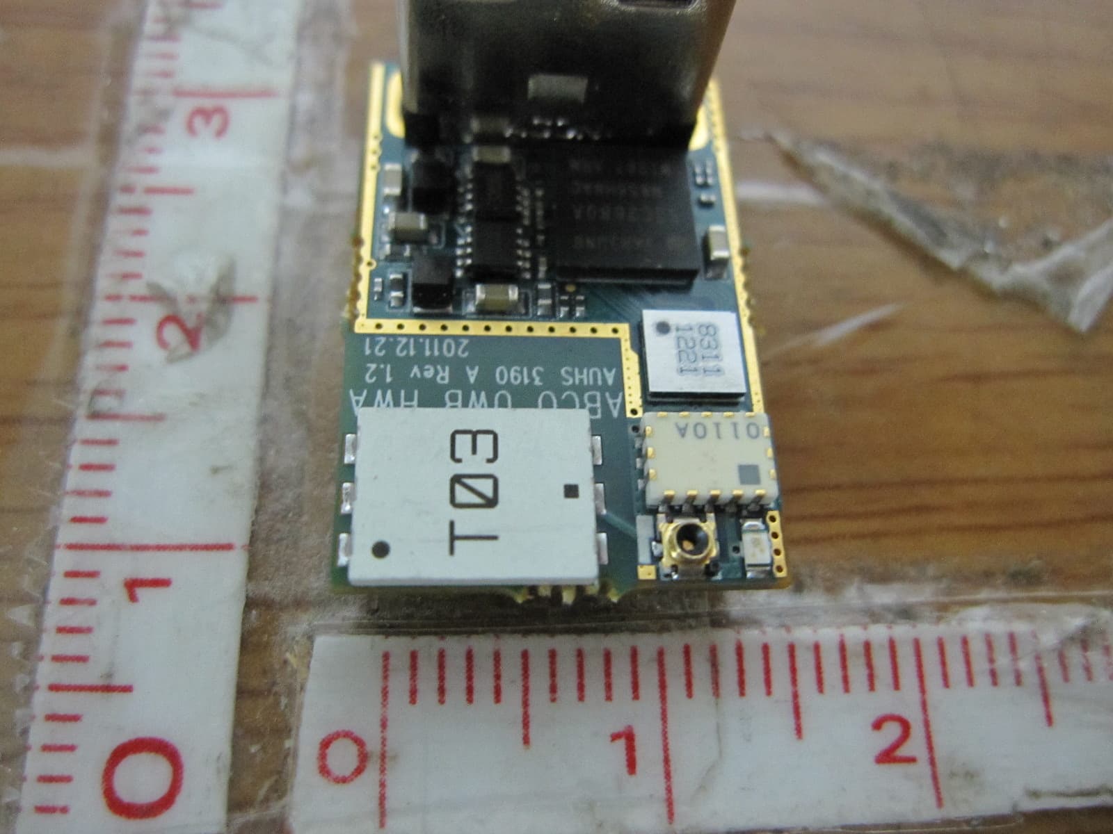
Q48-AUHS-3190-A
Jan 17, 2013UWB Wireless USB Dongle
Equipment Class
UWB - Ultra Wideband Transmitter