Q4F4353Sentry II Hand Held Remote
Truth Hardware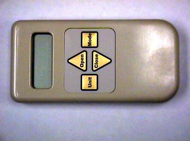
Click to zoom
Application Details
- Equipment Class
- DSC - Part 15 Security/Remote Control Transmitter
- Date of Grant
- Aug 13, 2003
- Application Purpose
- Original Equipment
- Date of Application
- Aug 13, 2003
- Equipment Note
- Sentry II Hand Held Remote
- Frequency Range
- 433.80000000 - 433.80000000
- Company
- Truth Hardware
- Country
- United States
Documents & Files
Document Text
Text extracted from the exhibit documents filed with the FCC. Open a document above to read the original.
Users Manual
Danger: To help prevent severe personal injury or death: oRead and understand instructions completely before beginning installation. oWhen connecting the Sentry 2 system to accessories, read the installation instructions supplied with each accessory before beginning installation. oSave ALL instructions. oInstaller – please be sure to give ALL instructions to the homeowner once installation is complete. o Wiring must be installed by a qualified electrician according to local and National Electrical Codes (N.E.C.) o Disconnect main power before beginning installation! Verify that power is OFF at the main breaker or fuse panel by testing with a voltage meter that you know is working correctly. o Connect power only after motor connections and settings are verified. o This equipment does not provide a method to shut off power, and should be connected to a dedicated breaker or fused power circuit. o The Sentry 2 system should not be used on windows that are intended to meet egress codes. o The Sentry 2 system is intended for indoor use only, with screens in place. o The screen interlock MUST be correctly mounted and is a required part of the installation. It is intended to help prevent injury that could result from reaching into the window or skylight area during operation. The correct installation of the screen interlock is the responsibility of the installer. oDo not allow children to operate the wall push buttons or remote control transmitter(s). LANGUAGES ENGLISH PAGE 1 ESPAÑOL PAGINA 10 FRANÇAIS PAGE 20 Made in USA An FKI Industries Company 700 West Bridge Street Owatonna, MN 55060 1-800-324-4487 www.truth.com Form 90059 R1 Hand Held Remote Operating Instructions Sentry II® Important Information oThis remote control is an RF (radio frequency) device and therefore does not need to be pointed in any manner toward the intended window/skylight to be operated. The effective range for this remote is approximately 100ft, but this varies with application conditions such as: wall materials, mounting height of receiver and interference from other devices radiating on RF frequencies. oDevices which could be affected or cause interference can include the following: radio baby monitors, garage door openers and automotive keyless entry / security systems. o oBatteries: This remote control uses 3 size “AAA” batteries (not included), Inserted with the proper polarities (+ and -) aligned correctly. The use of alkaline batteries is recommended for best service life. Do not mix alkaline and manganese battery types, nor use old and new batteries together. oA battery icon ““ will become visible on the LCD when the batteries are down to 20% of usable life. When the battery icon ““ begins to flash the batteries no longer provide enough power to operate the remote consistently, and therefore should be replaced. C Motor Unit Battery Icon Regulatory Compliance United States of America Federal Communications Commission (FCC) Unintentional emitter per FCC Part 15 Note: This equipment has been tested and found to comply with the limits for a Class B digital device, pursuant to part 15 of the FCC Rules. These limits are designed to provide reasonable protection against harmful interference in a residential installation. This equipment generates, uses, and can radiate radio frequency energy and, if not installed and used in accordance with the instructions may cause harmful interference to radio communications. However, there is no guarantee that interference will not occur in a particular installation. If this equipment does cause harmful interference to radio or television reception, which can be determined by turning the equipment off and on, the user is encouraged to try to correct the interference by one or more of the following measures: oReorient or relocate the receiving antenna. oIncrease the separation between the equipment and receiver. oConnect the equipment into an outlet on a circuit different from that to which the receiver is connected. oConsult the dealer or an experienced radio/TV technician for help. Warning: Changes or modifications not expressly approved by Truth Hardware could void the FCC compliance and negate your authority to operate the product. FCC Declaration of Conformity According to 47 CFR, Parts 15.107 and 15.109 Class B Responsible party: Truth Hardware, 700 West Bridge St., Owatonna, MN 55060 www.truth.com or 1-800-324-4487 Product: Sentry 2 Hand Held Remote (43.53) This device complies with part 15 of the FCC Rules. Operation is subject to the following two conditions: (1) This device may not cause harmful interference, and (2) this device must accept any interference received including interferences that may cause undesired operation. Canada Industry Canada (IC) Unintentional emitter per ICES-003 This class B digital apparatus complies with Canadian ICES-003. Cet appareil numérique de la classe B est conforme á la norme NMB-003 du Canada. Operation is subject to the following two conditions: (1) this device may not cause interference, and (2) this device must accept any interference, including interference that may cause undesired operation of the device. Europe European Community EMC Directive (CE) Compliance with these directives implies conformity to the following European Norms or Regulations: Emissions Immunity ETSI EN 300-220-3 v1.1.1 (2000-09) ETSI EN 301 489-3 v1.4.1 (2000-04) ETSI EN 301 489-3 v1.4.1 (2000-04) Programming the Remote Control If optional Hand Held Remote was purchased, it can now be programmed using the “Learn” button (see S1 on wire diagram) Program the remote using the following steps: Place three “AAA” batteries into the Remote. The display on the Remote will be blank except for the word “SET” Set Unit Mode Open Close Press the “Learn” button (S1) on the control board once Grey Green Grey Grey Grey Green Green Green Ye l l o w Yellow Yellow Grey Grey Re d Black Bl u e Bl u e Bl u e 12 1212 12 10 1010 10 7 77 7 5 55 5 4 44 4 S2 S2S2 S2 S1 S1S1 S1 12 34 5 6 o…
Text truncated - open the document above for the full version.
Block Diagram
U1 Microprocessor 32.768 KHz OSC. Keeloq (Rolling Code) RCT-433-AS RF Transmitter 433.92 MHz LCD Display Key Pad Truth Remote RF Transmitter Hardware Block Diagram 4 I/O lines LED 3 volt battery regulator Battery Detect Temperature Sensor TEMP F or C Switch ANTENNA COPPER TRACK ON PCB U6 U5 U2, U3 R1 S1 U4 A1 4/14/2003 REMOTERF_01 TRUTH
External Photos
FCC ID:Q4F4353 April, 2003 Page 17 of 24 EXHIBIT III EXHIBIT IIIEXHIBIT III EXHIBIT III EXTERNAL PHOTOS EXTERNAL PHOTOSEXTERNAL PHOTOS EXTERNAL PHOTOS FCC ID:Q4F4353 April, 2003 Page 18 of 24 External Photo FCC ID:Q4F4353 April, 2003 Page 19 of 24 External Photo
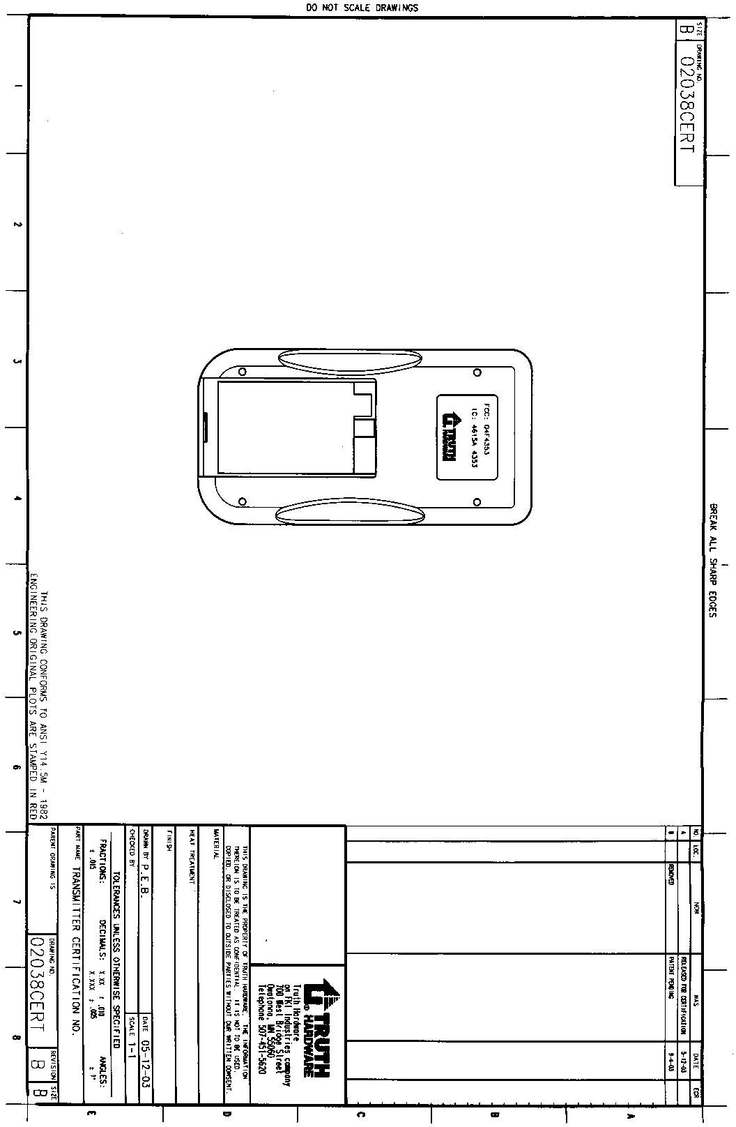
ID Label/Location Info
FCC: Q4F4353 CANADA IC: 4615A-4353
Internal Photos
FCC ID:Q4F4353 April, 2003 Page 20 of 24 EXHIBIT IV EXHIBIT IVEXHIBIT IV EXHIBIT IV INTERNAL PHOTOS INTERNAL PHOTOSINTERNAL PHOTOS INTERNAL PHOTOS FCC ID:Q4F4353 April, 2003 Page 21 of 24 Internal Photo FCC ID:Q4F4353 April, 2003 Page 22 of 24 Internal Photo
Operational Description
SENTRY II MODES OF OPERATION RECEIVER/CONTROLLER: The receiver has four PWM soft start motor driver output channels. Drivers control start, stop, direction and have over current detection. Motor drivers can be controlled by three separate input methods or modes. • User Interface Push Buttons on case assembly. • High Priority Interface (HPI) Input. (Alarm Inputs) • Remote RF control link using Keeloq (Rolling Code) security decoding at 433.92 Mhz. Using a Radiotronix Inc. receiver P/N RCR-433-HP. REMOTE /TRANSMITTER: Transmitter is a Radiotronix Inc. P/N RCT-433-AS, at 433.92 Mhz. using (OOK Modulation) user activated. • Battery operated 3 – AAA Alkaline cells regulated to 3.0 VDC. • Transmitter using Keeloq (Rolling Code) for encoding and security. • Transmitter antenna is an etched copper trace on the PCB. • Remote can encode up to nine window / skylight receiver units. PCB POWER/GROUND PLANES: Receiver/Controller has separate ground and power layers and two signal layers and the Remote /Transmitter PCB has a separate ground layer, power and signal are on a common layer. RCT-433-AS 1 Preliminary Rev Date: 5/21/01 Suface Mount 433.92 MHz SAW-Stabilized OOK Transmitter nDesigned for Short-Range Remote Control Applications nWorks with OOK/ASK Receivers n>600 foot operating range when used with RCR-433-HP receiver n4800 Baud Data Rate The RCT-433-AS is ideal for remote control applications where low- cost and longer range are required. The transmitter operates from a 1.5-12V supply, making it ideal for battery powered applications. The transmitter employs a SAW-stabilized oscillator, ensuring accu- rate frequency control for best range performance. Output power and harmonic emissions are easy to control, making FCC and ETSI com- pliance easy. The manufacturing-friendly SMT style package and low-cost make the RCT-433-AS suitable for high volume applications. APPLICATIONS nRemote Keyless Entry (RKE) nRemote Lighting Controls nOn-Site Paging nAsset Tracking nWireless Alarm and Security Systems nLong Range RFID KEY FEATURES nLow-Cost n1.5-12V operation n5mA current consumption at 3V n0dBm output power at 3V nSmall size: .25” x .4” n4800 baud operation Figure 1. Mechanical DrawingFigure 2. Suggested Pad Layout RCT-433-AS 2 Preliminary Rev Date: 5/21/01 RatingValueUnits Power Supply and All Input Pins-0.3 to +15VDC Absolute Maximum Ratings Storage Temperature-50 to +100°C Soldering Temperature (10 sec) 1 350 °C CharacteristicSymbolMinTypMaxUnitsNotes Operating VoltageV cc 1.53.012VDCnone Operating Current - DATA=VCCI cc ---4.5---mA@ 3V Frequency AccuracyTOL fc -750+75kHz@ 3V Center FrequencyF c --433.92---MHznone Output Powernone --- 0 --- dBm@ 3V Baud Rate - NRZnoneDC---4800BPSnone Electrical Characteristics Operating Temperature RangeT op °CTBD-20 --- +70 PinNameDescription 1ANT 50 ohm antenna output. The antenna port impedence affects output power and harmonic emissions. An L-C low-pass filter may be needed to suffi- ciently filter harmonic emissions. GNDTransmitter ground. Connect to ground plane. 3 2 DATA Digital data input. This input is CMOS compatible and should be driven with CMOS level inputs. 4 Pin Description Notes: 1). Hand solder only. The transmitter is not suitable for reflow soldering. VCC Pins 4 provides operating voltage for the transmitter. VCC should be bypassed with a .01uF ceramic capacitor and filtered with a 4.7uF tantalum capacitor. Noise on the power supply will degrade transmitter noise performance. Operating Current - DATA=GNDI cc ---1.5---uA@ 3V RCT-433-AS 3 Preliminary Rev Date: 5/21/01 Theory of Operation OOK Modulation OOK modulation is a binary form of amplitude modulation. When a logical 0 is being sent, the carrier is fully supressed. When a logical 1 is being sent, the carrier is fully on. OOK is the modulation method of choice for remote control applications where power consumption and cost are the primary factors. Because OOK transmitters draw no power when they transmit a 0, they exhibit significantly better power consumption than FSK transmitters. OOK data rate is limited by the start-up time of the oscillator. High-Q oscillators which have very stable center frequencies take longer to start-up than low-Q oscillators. The start-up time of the oscillator deter- mines the maximum data rate that the transmitter can send. SAW stabilized The transmitter is basically a negative resistance LC oscillator whose senter frequency is tightly controlled by a SAW resonator. SAW (Surface Accoustic Wave) resonators are fundamental frequency devices that resonate at frequencies much higher than crystals. Data Rate The oscillator start-up time is on the order of 40uSec, which limits the maximum data rate to 4.8 kbit/sec. Power Supply The RCT-433-AS is designed to operate from a 1.5- 12V power supply. It is crucial that this power supply be very quiet. The power supply should be bypassed using a 0.01uF low-ESR ceramic capacitor and a 4.7uF tantalum capacitor. These capacitors should be placed as close to the power pins as possible. Antenna Output Pin 1 is a 50 ohm antenna output. It will support most antenna types, including printed antennas integrated directly onto the PCB. The performance of the different antennas varies. Please refer to the applications note “Antennas 101” for more information on antennas. This applications note also includes information on microstrip trans- mission lines. Any time a trace is longer than 1/8th the wavelength of the frequency it is carrying, it should be a 50 ohm microstrip. Regardless of the antenna type chosen, the VSWR at the antenna port should be <2:1. Ideally, the impedence at the antenna port would be 50 ohms resistive. The impedence at the antenna power affects the VSWR, power output, and harmonic output of the transmitter. In some cases, the output of the transmitter may need a low-pass LC filter to reduce harmonic emis- sions. Check with our technical support department for more information. Radiotronix, Inc. 1141 SE Grand Suite …
Text truncated - open the document above for the full version.
Schematics
Xmtr04_20030120.sch-1 - Mon Jan 20 11:23:16 2003 Xmtr04_20030120.sch-2 - Mon Jan 20 11:23:24 2003 Bill of Materials for Truth Hardwa re Transmitter Board Rev. 04 (2075) # Qty Reference Description Value Manufacturer J. Gordon Electronic Design, Inc. Xmtr04_20030120.doc Page 1 of 3 Date 01/20/03 Preliminary 1. 1 A1 LCD DISPLAY MODULE, CUSTOM GRAPHIC LCD LXD H4023A 2. 2 C1 C12 CAPACITOR, CERA MIC, 150PF, 50V, 5%, C0G / NPO, 0805, SMD 150PF (ANY) AVX 08055A151JAT KEMET C0805C151J5GAC PANASONIC ECU-V1H151JCG DIGI-KEY PCC151CGCT-ND 3. 3 C11 C15 C19 CAPACITOR. TANTALUM, EIA-B , 4.7UFD, 10VDC, 10% 4.7UF 10V KEMET T491B475K010AS 4. 1 C18 CAPACITOR, CERAMIC, 2200PF, 50V, 10%, X7R, 2012 (0805), SMD 2200PF (ANY) AVX 08055C222KAT PANASONIC ECU-V1H222KBN DIGI-KEY PCC222BNCT-ND 5. 2 C2 C16 TBD 6. 3 C3 C9-10 CAPACITOR, CERA MIC, 0.1UF, 50V, 10%, X7R, 2012 (0805), SMD 0.1UF (ANY) CAL-CHIP GMC21X7R104K50NT PANASONIC ECJ2YB1H104K DIGI-KEY PCC1840TR-ND 7. 2 C4-5 CAPACITOR, CERA MIC, 22PF, 50V, 5%, NPO, 2012 (0805), SMD 22PF (ANY) AVX 08055A220JAT PANASONIC ECU-V1H220JCN DIGI-KEY PCC220CNCT-ND 8. 6 C7-8 C13-14 C6 C17 CAPACITOR, CERAMIC, .01UF, 50V, 10%, X7R, 2012 (0805), SMD .01UF (ANY) AVX 08055C103KAT PANASONIC ECUV1H103KBG DIGI-KEY PCC103BNCT-ND 9. 1 D1 RECTIFIER, SCHOTTKY BARRIER, 40V, 0.5A, VF 0.55V, SMD ZHCS500 (ANY) ZETEX ZHCS500TA DIGI-KEY ZHC500CT-ND 10. 1 J1 CONNECTOR ASSEMBLY, ZIF-LINE, 5 POS, 1.27 (0.050") SPACING, FLEX-FILM 5 POS ZIF AMP 5-487576-0 Bill of Materials for Truth Hardwa re Transmitter Board Rev. 04 (2075) # Qty Reference Description Value Manufacturer J. Gordon Electronic Design, Inc. Xmtr04_20030120.doc Page 2 of 3 Date 01/20/03 Preliminary 11. 1 J2 HEADER, .1"LS .025"SQ POST, 2 POS. (ANY) SULLINS PCT02SAAN DIGI-KEY S1012-02-ND 12. 2 J3-4 WIRE POINT ON PCB N/A N/A - ON PCB 13. 1 JP1 SHUNT, SHORTING BLOCK .1"LS DIGI-KEY 929950-00-ND DIGI-KEY 929950-06-ND DIGI-KEY 929957-08-ND 14. 1 L1 TBD 15. 1 L2 TBD 16. 1 R1 THERMISTOR, 10K, NTC, 5%, RADIAL 10K (ANY) PANASONIC ERTD2FHJ103S 17. 1 R11 RESISTOR, 2.4K, 5%, 1/10W, 2012 (0805), SMD 2.4K (ANY) DIGI-KEY P2.4KACT-ND 18. 3 R2-4 RESISTOR, 1.0M, 5%, 1/10W, 2012 (0805), SMD 1M (ANY) DIGI-KEY P1.0MACT-ND 19. 2 R5 R10 RESISTOR, 100K, 5%, 1/10W, 2012 (0805), SMD 100K (ANY) DIGI-KEY P100KACT-ND 20. 3 R6-8 RESISTOR, 10.00K, 1%, 1/10W, 2012 (0805), SMD 10K 1% (ANY) PANASONIC ERJ6ENF1002 DIGI-KEY P10.0KCCT-ND 21. 1 R9 RESISTOR, 100, 5%, 1/10W, 2012 (0805), SMD 100 (ANY) DIGI-KEY P100ACT-ND 22. 1 RN1 NETWORK, 100K, 1/16W, ISOLATED, 4 RESISTORS, SMD 100K CTS 742083104J DIGI-KEY 742-083-R104CT-ND 23. 1 S1 DIP, SPST, 2 POS, AU, SEALED , SMD SD02H0SK C&K COMPONENTS, INC. SD02H0SK DIGI-KEY CKN3054-ND 24. 6 T1-6 TESTPOINT N/A - COPPER PAD ON PCB Bill of Materials for Truth Hardwa re Transmitter Board Rev. 04 (2075) # Qty Reference Description Value Manufacturer J. Gordon Electronic Design, Inc. Xmtr04_20030120.doc Page 3 of 3 Date 01/20/03 Preliminary 25. 1 U1 MICROCONTROLLER , MIXED SIGNAL, 8K, 16BIT, LCD DRIVER, 1.8-3.6VDC, SMD MSP430F413IPM TEXAS INSTRUMENTS MSP430F413IPM 26. 1 U2 VOLTAGE DETECTI ON, 3.2VDC, N-CH OPEN DRAIN OUTPUT, SMD 3.2V PANASONIC MN13821-M(TX) DIGI-KEY MN13821-MCT-ND DIGI-KEY MN13821-MTR-ND 27. 1 U3 VOLTAGE DETECTI ON, 3.8VDC, N-CH OPEN DRAIN OUTPUT, SMD 3.8V PANASONIC MN13821-Q(TX) DIGI-KEY MN13821-QCT-ND DIGI-KEY MN13821-QTR-ND 28. 1 U4 VOLTATGE REGULATOR, LINEAR, 3.0VDC, 0.15A, LDO, L PWR, SMD 3.0VDC TEXAS INSTRUMENTS TPS76330DBVT TEXAS INSTRUMENTS TPS76330DBVR ZETEX ZXCL300E5 29. 1 U5 ENCODER, CODE HOPPING, KEELOQ, SMD HCS300SN MICROCHIP HCS300SN 30. 1 U6 TRANSMITTER, 433.92MHZ, OOK, SAW- STABILIZED, SMD RCT-433-AS RADIOTRONI X, INC. RCT-433-AS 31. 1 X1 CRYSTAL, 32.768KHZ, SERIES RESISTANCE 35 OHM 32.768KHZ EPSON AMERICA INC. C-001R 32.768K-A DIGI-KEY SE3201-ND
Test Report
Truth Hardware Application For Certification Sentry 2 Skylite Remote Control Transmitter Sentry 2 Skylite Remote Control TransmitterSentry 2 Skylite Remote Control Transmitter Sentry 2 Skylite Remote Control Transmitter FCC ID: Q4F4353 FCC ID: Q4F4353FCC ID: Q4F4353 FCC ID: Q4F4353 April 22, 2003 This report is for the exclusive use of ITS's Client and is provided pursuant to the agreement between ITS and its Client. ITS's responsibility and liability are limited to the terms and conditions of the agreement. ITS assumes no liability to any party, other than to the Client in accordance with the agreement, for any loss, expense or damage occasioned by the use of this report. Only the Client is authorized to copy or distribute this report and then only in its entirety. Any use of the ITS name or one of its marks for the sale or advertisement of the tested material, product or service must first be approved in writing by ITS. The observations and test results in this report are relevant only to the sample tested. This report by itself does not imply that the material, product, or service is or has ever been under an ITS certification program. Intertek IntertekIntertek Intertek 7250 Hudson Boulevard, Suite 100, Oakdale, MN 51228 Telephone 651-730-1188, Fax 651-730-1282 Home Page www.etlsemko.com TABLE OF CONTENTS TABLE OF CONTENTSTABLE OF CONTENTS TABLE OF CONTENTS 1.0 1.01.0 1.0 General Description General DescriptionGeneral Description General Description ............................................................................................1 1.1 Related Submittal(s) Grants ..........................................................................1 1.2 Product Description ...................................................................................1 1.3 Test Methodology .....................................................................................2 1.4 Test Facility ............................................................................................2 2.0 2.02.0 2.0 System Test Configuration System Test ConfigurationSystem Test Configuration System Test Configuration ....................................................................................3 2.1 Justification .............................................................................................3 2.2 EUT Exercising Software ............................................................................3 2.3 Special Accessories....................................................................................3 2.4 Equipment Modification ..............................................................................3 2.5 Support Equipment List and Description ..........................................................3 2.6 Test Configuration Block Diagram .................................................................4 3.0 3.03.0 3.0 Test Results Test ResultsTest Results Test Results ......................................................................................................5 3.1 Radiated Emissions, FCC 15.109, Class B .......................................................6 3.2 Transmitting Time, FCC 15.231(a)(1).............................................................7 3.3 Field Strength of Fundamental and Spurious Emissions, FCC 15.231(b) ...................8 3.4 Bandwidth of Emissions, FCC 15.231(c) .........................................................9 3.5 Test Procedure ....................................................................................... 10 3.6 Field Strength Calculation.......................................................................... 11 4.0 4.04.0 4.0 Test Equipment Test EquipmentTest Equipment Test Equipment ................................................................................................ 12 EXHIBIT I EXHIBIT IEXHIBIT I EXHIBIT I Test Set Up Photographs ..................................................................................... 13 EXHIBIT II EXHIBIT IIEXHIBIT II EXHIBIT II FCC ID Label Location ...................................................................................... 16 EXHIBIT III EXHIBIT IIIEXHIBIT III EXHIBIT III External Photographs ......................................................................................... 17 EXHIBIT IV EXHIBIT IVEXHIBIT IV EXHIBIT IV Internal Photographs .......................................................................................... 20 EXHIBIT V EXHIBIT VEXHIBIT V EXHIBIT V Electrical Schematics and Block Diagram................................................................. 23 EXHIBIT VI EXHIBIT VIEXHIBIT VI EXHIBIT VI User Manual and Operational Description ................................................................ 24 FCC ID:Q4F4353 April, 2003 Page 1 of 24 1.0 1.0 1.0 1.0 GENERAL DESCRIPTION GENERAL DESCRIPTIONGENERAL DESCRIPTION GENERAL DESCRIPTION 1.1 1.1 1.1 1.1 Related Submittals Grants Related Submittals GrantsRelated Submittals Grants Related Submittals Grants This is single application of the Truth Hardware Remote Control Transmitter Model: Sentry 2 Skylite for Certification under FCC Part 15, Subpart C. There are no other simultaneous applications. The Receiver portion will be verified under Declaration of Conformity. 1.2 1.2 1.2 1.2 Product Description Product DescriptionProduct Description Product Description The Sentry 2 Skylite Remote Control Transmitter is a RF remote control operating in 433.8MHz. The intended use of the Sentry 2 Skylite Remote Control Transmitter is to generate and transmit a RF signal to control window opener. The Sentry 2 Skylite Remote Control Transmitter powered at 4.5VDC from three AAA-size internal batteries. Antenna Description: Integrated antenna FCC ID:Q4F4353 April, 2003 Page 2 of 24 1.3 1.31.3 1.3 Test Methodology Test MethodologyTest Methodology Test Methodology Emission measurements were performed according to the procedures in ANSI C63.4-2000. All field strength radiated emissions measurements were performed in…
Text truncated - open the document above for the full version.
Test Setup Photos
FCC ID:Q4F4353 April, 2003 Page 13 of 24 EXHIBIT I EXHIBIT IEXHIBIT I EXHIBIT I TEST SET UP PHOTOS TEST SET UP PHOTOSTEST SET UP PHOTOS TEST SET UP PHOTOS FCC ID:Q4F4353 April, 2003 Page 14 of 24 Radiated Emissions Test Configuration FCC ID:Q4F4353 April, 2003 Page 15 of 24 Radiated Emissions Test Configuration
Contact Information
Applicant
Donald L Boesen(Technical Specialist)
Technical Contact
Truth HardwareDonald Boesen
[email protected](507)444-4487
700 West Bridge Street · Owatonna, Minnesota · United States
Non-Technical Contact
Intertek Testing ServicesYuriy Litvinov
[email protected](651) 730-1188
Test Firm
Intertek Testing ServicesUri Spector
Technical Specifications
| # | Rule Parts | Frequency Range | Power Output |
|---|---|---|---|
| 1 | 15.231 | 433.8 MHz - 433.8 MHz | - |