Q6AXMHG0578ActiGait� Control Unit
Neurodan A/S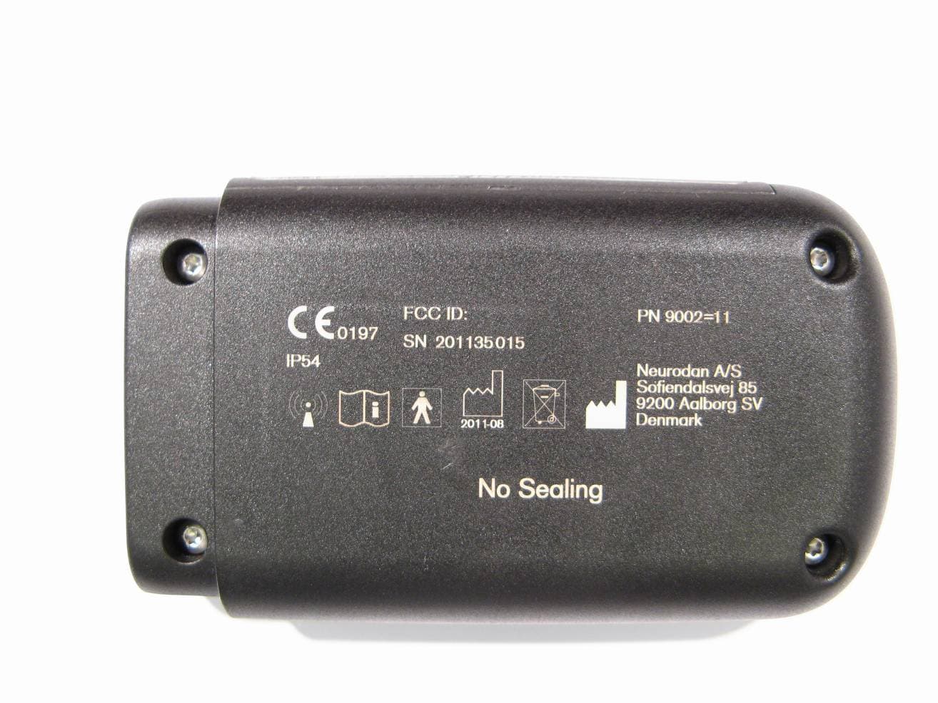
Click to zoom
Application Details
- Equipment Class
- DXX - Part 15 Low Power Communication Device Transmitter
- Date of Grant
- Sep 06, 2012
- Application Purpose
- Original Equipment
- Date of Application
- Sep 06, 2012
- Equipment Note
- ActiGait� Control Unit
- Frequency Range
- 2401.00000000 - 2401.00000000
- Company
- Neurodan A/S
- Country
- Denmark
Documents & Files
Document Text
Text extracted from the exhibit documents filed with the FCC. Open a document above to read the original.
Users Manual
1 23 456 78 1: ActiGait® Heel Switch 2: ActiGait® Belt Loop 3: ActiGait® Body Clip 4: ActiGait® Belt Clip 5: ActiGait® Control Unit 6: ActiGait® Antenna 7: ActiGait® Heel Sock 8: ActiGait® Antenna Fixture 9: ActiGait® Charger (model FW7711/0.7) incl. plugs 10: ActiGait® Charger Cable 9a9b9c9d 9 10 ActiGait® Implantable Drop Foot Stimulator User Manual 2 1. Introduction ......................................3 2. Intended Use ....................................3 2.1 Medical Purpose ....................................3 2.2 Application.............................................3 2.3 Qualification of Clinician ..........................3 2.4 Follow up Schedule ................................3 3. Indications/Contraindications ....4 3.1 Indications ............................................4 3.2 Contraindications ...................................4 4. Warnings and Precautions ...........5 4.1 Safety precautions .................................5 4.2 Warnings ...............................................5 4.3 General cautions ...................................7 4.4 Potential Risks/Side effects .....................9 5. Service Information ......................11 5.1 Scope of Delivery .................................11 5.2 Service ................................................11 6. Description of the ActiGait® .......12 6.1 The ActiGait® Implant ...........................13 6.2 The ActiGait® .......................................14 7. How ActiGait® works ...................15 7.1 The Control Unit ...................................16 7.1.1 The On/Off Button .............................17 7.1.2 The Stimulation Intensity Buttons .........18 7.1.3 The Mute Button ................................19 7.1.4 The Pairing Button .............................21 7.1.5 The Control Unit Battery Indicator ........22 7.1.6 The Heel Switch Battery Indicator ........23 7.1.7 Training Mode Indicator ......................25 7.1.8 Mute Indicator ...................................27 7.1.9 Stimulation Intensity Indicators ............27 7.2 Putting On the Control Unit ....................27 7.2.1 The Belt Clip .....................................28 7.2.2 The Belt Loop ....................................28 7.2.3 The Body Clip ...................................29 7.3 Putting On the Antenna Fixture ...............30 7.4 Putting On the Antenna .........................33 7.5 The Heel Switch ...................................35 7.5.1 The Heel Sock ...................................36 7.5.2 Heel Switch Feedback........................37 7.6 The Charger ........................................38 7.6.1 Charging the Control Unit ...................39 7.6.2 Travel Kit for Charger .........................41 7.7 Audio Signals and Warnings ..................42 7.7.1 Warnings ..........................................42 7.7.2 Audio Signals ....................................43 8. Lights and Audio Signals............43 8.1 How to Interpret the Light Indicators .......44 8.2 How to Interpret the Audio Signals .........46 9. Troubleshooting for ActiGait® ...49 10. Warranty .........................................51 11. Expected lifetime .......................52 12. Cleaning, Storage and Disposal ...........................................52 12.1 Cleaning ............................................52 12.2 Storage.............................................53 12.3 Disposal ............................................53 13. Available Articles .......................53 14. Technical Data ..............................55 14.1 ActiGait® Control Unit..........................55 14.2 ActiGait® Belt Clip ..............................56 14.3 ActiGait® Belt Loop .............................56 14.4 ActiGait® Body Clip ............................57 14.5 ActiGait® Antenna ..............................57 14.6 ActiGait® Antenna Fixture .....................58 14.7 ActiGait® Heel Switch ..........................58 14.8 ActiGait® Heel Sock ............................59 14.9 19.9 ActiGait® Charger Cable ..............59 14.10 ActiGait® Charger .............................60 14.11 ActiGait® Implant ..............................61 14.11.1 X-Ray Identification .........................62 15. Classification ................................62 16. List of symbols .............................63 16.1 Ingress Protection ...............................65 17. Declaration of Conformity .......65 3 1. Introduction This manual describes the use of the ActiGait® and is directed towards individuals with an ActiGait® Implant. The manual is to be used as an information resource and an instruction manual. The term “User” defines individuals who have an ActiGait® Implant and thereby are users of the ActiGait®. For clinicians the Clinician Manual (647G805=GB) is available 2. Intended Use 2.1 Medical Purpose The ActiGait® is solely to be used as treatment in patients having a drop foot follow- ing an upper motor neuron lesion. 2.2 Application The ActiGait® system is a partially implantable medical device for treatment of drop foot which activates the muscles of the lower leg during walking. The system is intended for use by persons suffering from paralysis of the ankle dorsiflexor muscles caused by damage to the central nervous system. The largest group of potential users are persons with hemiplegia as a consequence of stroke. The system will not function for people with drop foot caused by peripheral nerve damage. 2.3 Qualification of Clinician The selection of users for ActiGait®, setup and adjustment are done by clinicians such as medical doctors, physiotherapists or equivalent. To be able to program and adjust the ActiGait®, the clinician must have obtained a certificate on usage of the Clinical Station software following training by Otto Bock 2.4 Follow up Schedule It is recommended that the ActiGait® is activated 1-3 weeks after implantation, as the wound healing must be finished first. The user should thereafter be followed close…
Text truncated - open the document above for the full version.
External Photos
Neurodan A/S Sofiendalsvej 85 DK-9200 Aalborg SV. Denmark Tlf: +45 70 27 22 97 Fax: +45 70 27 22 17 External Photos: ActiGait® Control Unit FCC ID: Q6AXMHG0578 Front View January 16, 2012 z Page 2 Rear View
ID Label/Location Info
June 22, 2012 Neurodan A/S Sofiendalsvej 85 DK-9200 Aalborg SV. Denmark Tlf: +45 70 27 22 97 Fax: +45 70 27 22 17 ID Label and Label location: ActiGait® Control Unit FCC ID: Q6AXMHG0578 Actual size:
Internal Photos
Neurodan A/S Sofiendalsvej 85 DK-9200 Aalborg SV. Denmark Tlf: +45 70 27 22 97 Fax: +45 70 27 22 17 Internal Photos: ActiGait® Control Unit FCC ID: Q6AXMHG0578 Bottom side January 16, 2012 z Page 2 Top side
Test Report
Test report no.1026496-4 Rev. B Page2 (19 ) Revision History Rev.DateOrder#Description A2011-03 -311026496First release B2012-06 -081026496Marker delta method for band-edge added Test report no.1026496-4 Rev. B Page3 (19 ) CONTENTS Page 1CLIENT INFORMATION..................................................................................................................4 2EQUIPMENT UNDER TEST(EUT)................................................................................................. 4 2.1IDENTIFICATIONOF THEEUTACCORDING TO THE MANUFACTURER/CLIENT DECLARATION...........4 2.2PERIPHERAL EQUIPMENT.................................................................................................................5 2.3TEST SIGNALS................................................................................................................................. 5 3TEST SPECIFICATIONS...................................................................................................................6 3.1STANDARDS....................................................................................................................................6 3.2ADDITIONS,DEVIATIONS AND EXCLUSIONS FROM STANDARDS.......................................................6 3.3TEST FACILITY................................................................................................................................6 3.4TEST SET-UP....................................................................................................................................6 3.5TEST CONDITIONS...........................................................................................................................6 4TEST SUMMARY...............................................................................................................................7 5RADIATED OUTPUT POWER .........................................................................................................8 5.1TEST PROTOCOL..............................................................................................................................8 5.2LIMIT..............................................................................................................................................8 6SPURIOUS EMISSIONS (RADIATED)............................................................................................9 6.1MEASUREMENT UNCERTAINTY.......................................................................................................9 6.2TEST EQUIPMENT............................................................................................................................9 6.3MEASUREMENT SET-UP.................................................................................................................10 6.4TEST GRAPHS, TXMODE...............................................................................................................11 6.5TEST GRAPHS, STANDBY/RXMODE..............................................................................................14 6.6TEST PROTOCOL, TXMODE...........................................................................................................16 6.7TEST PROTOCOL, STANDBY/RXMODE..........................................................................................16 7OCCUPIED BANDWIDTH..............................................................................................................17 7.1TEST EQUIPMENT..........................................................................................................................17 7.2TEST PROTOCOL............................................................................................................................17 8BAND EDGE......................................................................................................................................18 8.1TEST EQUIPMENT..........................................................................................................................18 8.2TEST PROTOCOL............................................................................................................................18 PHOTO OF THE EUT..............................................................................................................................19 Test report no.1026496-4 Rev. B Page4 (19 ) 1CLIENT INFORMATION The EUT has been tested by request of Company:Neurodan A/S Sofiendalsvej 85 DK-9200 Aalborg SV Denmark Name of contact:Eigil Myrhoj Nielsen 2EQUIPMENT UNDER TEST(EUT) 2.1Identificationof the EUT according to the manufacturer/client declaration Equipment:Medical device for treatment of dropfoot Type/Model:ActiGait, EXU Brand name:ActiGait Serial number:Unmarked Manufacturer:NeurodanA/S Frequencyrange:2401MHz(one channel) Frequency agile or hopping:YesNo Antenna:Internal antennaExternal antenna Antenna connector:None, i nternal antennaYes Antenna gain:< 0dBi Rating RF output power:0 dBm Duty cycle:- Type of modulation:MSK Test report no.1026496-4 Rev. B Page5 (19 ) 2.2Peripheral equipment Peripheral equipment is defined as equipment needed for correct operation of the EUT duringthe tests, but not included as a part of the testing and evaluation of the EUT. Manufacturer / TypeSerial number Neurodan, ActiGait, ANTUnmarked 2.3Test signals 1.Continous TX with modulation (white noise) 2.Continous TX without modulation Test report no.1026496-4 Rev. B Page6 (19 ) 3TEST SPECIFICATIONS 3.1Standards FCC 47 CFR part 15 (2010) Subpart B– Unintentional radiators FCC 47 CFR part 15 (2010) Subpart C– Intentional Radiators; §15.249 Operation within the bands 902-928 MHz, 2400– 2483.5 MHz, 5725– 5850 MHz and 24.0– 24.25 GHz RSS-Gen, Issue 3 (December 2010): General Requirements and Information for the Certification of Radiocommunication Equipment RSS-210, Issue 8 (December 2010): Low Power Licence-Exempt Radio communication Devices (All Frequency Bands): Category I Equipment. Measurements methods according to…
Text truncated - open the document above for the full version.
Test Setup Photos
1(1) TEST SET-UP PHOTOS – XMHG0578 Radiated spurious emission
Contact Information
Applicant
Morten Hansen(R&D Engineer)
Test Firm
Intertek SEMKO ABNiklas Bostrom
Technical Specifications
| # | Rule Parts | Frequency Range | Power Output |
|---|---|---|---|
| 1 | 15C | 2.40 GHz - 2.40 GHz | - |
Other Applications from Neurodan A/S
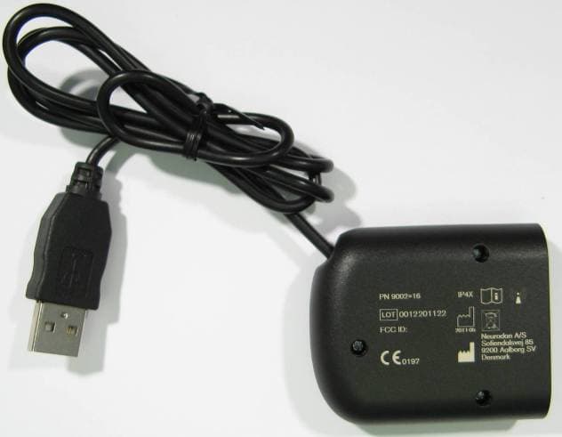
Q6AXMHG0583
Sep 06, 2012ActiGait� Clinical Interface
Equipment Class
DXX - Part 15 Low Power Communication Device Transmitter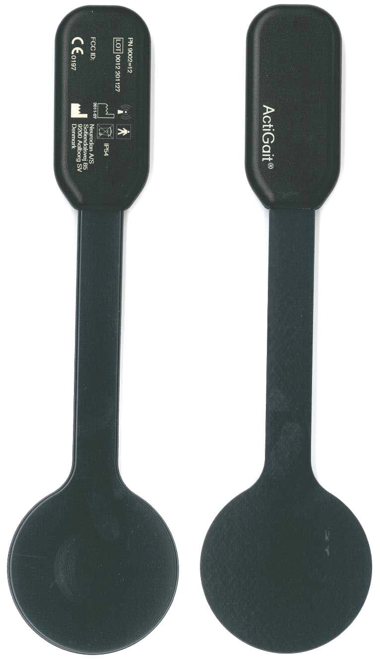
Q6AXMHG0575
Sep 06, 2012ActiGait� Heel Switch
Equipment Class
DXX - Part 15 Low Power Communication Device Transmitter