Q6R-HHTX-ASW-433KEYFOB TRANSMITTER
RF Laboratories, Inc.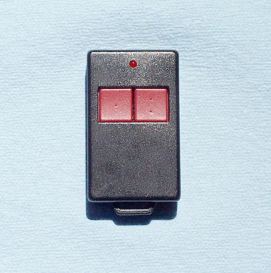
Click to zoom
Application Details
- Equipment Class
- DSC - Part 15 Security/Remote Control Transmitter
- Date of Grant
- Jul 20, 2003
- Application Purpose
- Original Equipment
- Date of Application
- Jul 20, 2003
- Equipment Note
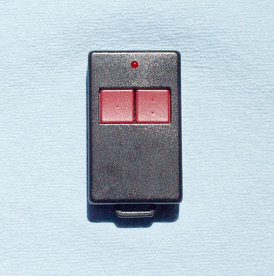
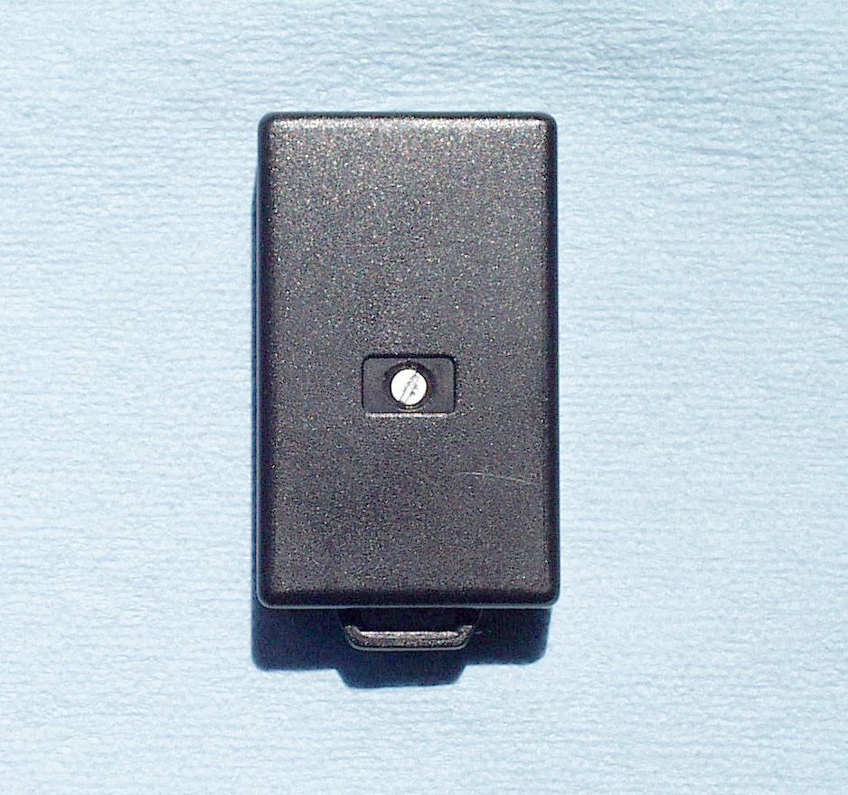
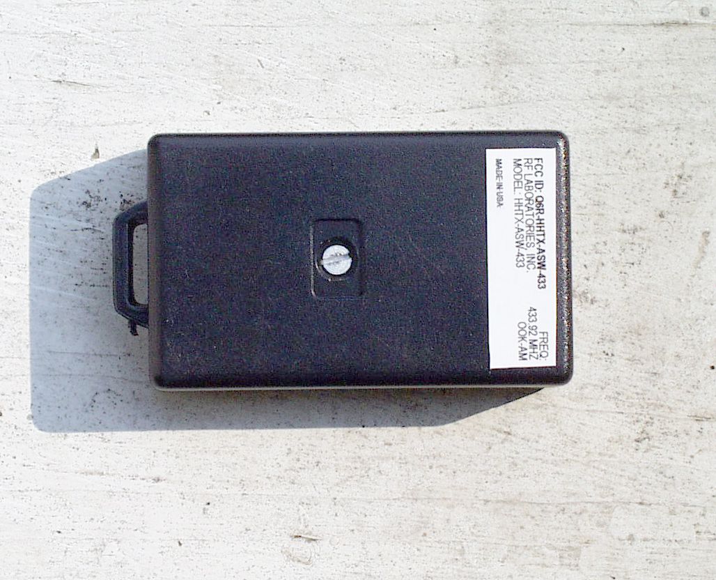
- KEYFOB TRANSMITTER
- Frequency Range
- 433.77000000 - 434.17000000
- Company
- RF Laboratories, Inc.
- Country
- United States
Documents & Files
Document Text
Text extracted from the exhibit documents filed with the FCC. Open a document above to read the original.
Users Manual
SPECIFICATIONS 1. Input. •Operating voltage: 12 VDC • Frequency: 433.92 MHZ SAW Stabilization • RF Operating Frequency: 433 MHZ • Range: Up to 2000 feet (depending on conditions) FEATURES •Transmitter Complies with FCC Part 15.231 •Wireless RF (Not IR) To Transmit Signal •Range: Up To 2000 Feet (Application Dependant) •One and Two Button Versions Available •Red LED Active Transmit Indication Light •Standard 12 VDC Battery Operation •Rugged Construction 2. Output. •433.92 MHZ (Nominal) AM OOK(ON-OFF KEYED) •Digital Transmission •10 Asyncronous Packets per second •2400 BPS/Baud Rate 433.92 MHZ AM TRANSMITTER 3. Mechanical. •Rugged ABS Case •Replaceable 12 Volt Battery •Water Resistant •Unique Internal Semi-Loop Antenna 1412 Center Ave · Oostburg · Wisconsin · 53070 Phone: (920) 564-2700 Fax: (920) 564-1027 Email: [email protected] TRANSMITTER New Product This device complies with part 15 of the FCC Rules. Operation is subject to the following two conditions: (1) This device may not cause harmful interference, and (2) this device must accept any interference received, includ- ing interference that may cause undesired operation. RF Laboratories cautions the user that changes or modifications not expressly approved by the party respon- sible for compliance could void the user’s authority to operate the equipment. FOR LONG-RANGE APPLICATIONS ONE AND TWO-BUTTON VERSIONS DIMENSIONS 1.46 2.40 .58 TRANSMITTER CONNECTION DIAGRAMS TRANSMITTER ORDERING INFORMATION PART NUMBER = HHTX-ASW-433 HHTX-ASW-433 RF Laboratories, Inc. BATTERY
Cover Letter(s)
RF LABORATORIES, INC 1412 Center Avenue Oostburg, WI 53070 (920)-564-2700 • FAX (920) 564-1027 • e-mail: [email protected] July 2, 2003 Federal Communications Commission 7435 Oakland Mills Road Columbia, MD 21046 Gentlemen: This letter is to comply with Section 0.457(d)(2)(i) pertaining to confidential material. RF Laboratories would like the following documents regarding this submission for FCC ID: Q6R- HHTX-ASW-433 to be kept confidential. 1. All schematics 2. Block diagrams 3. Circuit descriptions The above material contains trade secrets or technical data, which would customarily be guarded from competitors. We do not want these documents to be accessible to the general public. Sincerely, David Zima RF Laboratories, Inc.
Test Report
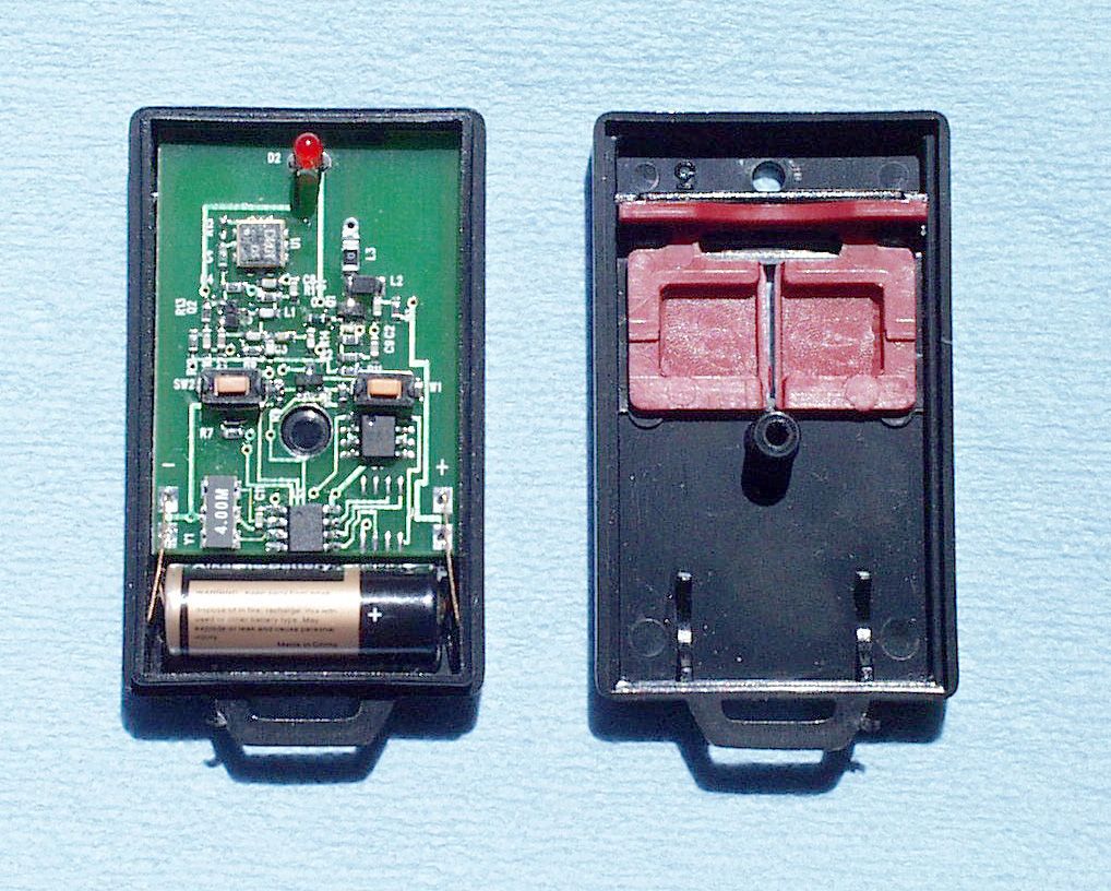
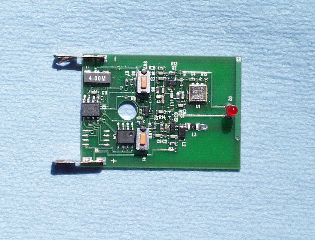
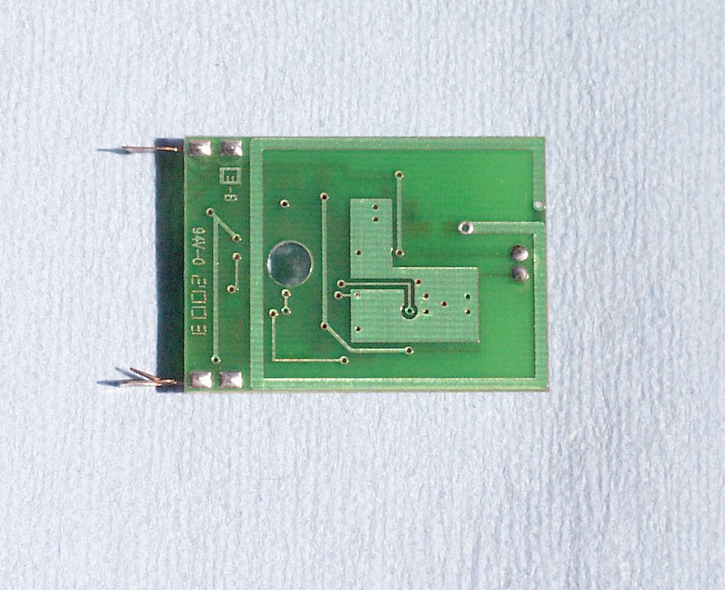
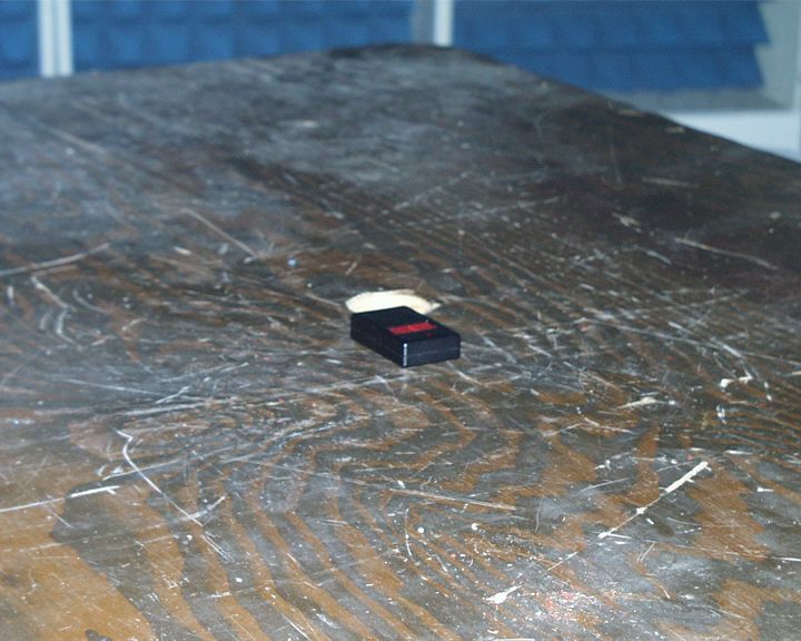
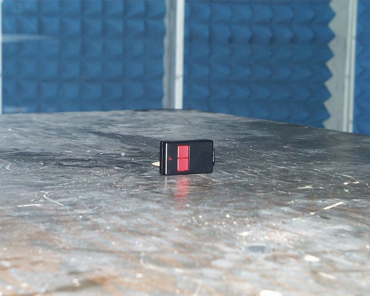
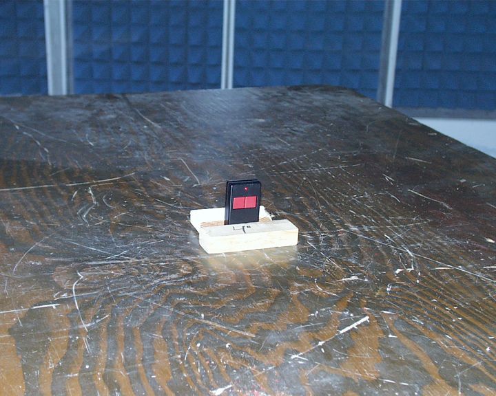
Q6R-HHTX-ASW-433 RF Laboratories Test Report of an Intentional Radiator for Certification under Part 15 of the FCC rules DUT: Keyfob Transmitter FCC ID Q6R-HHTX-ASW-433 Section 15.231 Date: 26-June-2003 Manufacturer: RF Laboratories, Inc. 1412 Center Avenue Oostburg, WI 53070 (920) 564-2700 Prepared by: Control Design & Testing, Inc. 6010 Red Fox Drive Spotsylvania, VA 22553 (540) 582-2826 1 Q6R-HHTX-ASW-433 RF Laboratories A. DEVICE UNDER TEST The product is a small keychain style transmitter used for general purpose remote control applications. The product is designed to operate under the provisions of Part 15.231 of the FCC rules in the United States and RSS-210 in Canada. The device is self contained in a plastic enclosure and is powered by an internal 12 volt alkaline batteryl. The circuitry is configured on a single circuit board with the radiating element etched as a loop on the board. There is no means to connect an external antenna. The frequency of operation is 433.92 MHz., nominal. The modulation mode is on/off keying using a 50% duty cycle, Manchester phase pulse position scheme. The packets consist of a start pulse (1.24ms.) followed by ten bit pulses (400μs. each). B. MEASUREMENT PROCEDURE: RADIATED EMISSIONS Radiated emissions testing of this device was conducted at the Carl T. Jones test facility located in Springfield, Virginia. FCC Site #90490 The field strength measurements were conducted according to the procedures set forth in ANSI C63.4 (1992). The device under test was placed on a rotating turntable 0.8 meters high, centered at 3 meters distant from the measurement antenna. The device was tested in three positions as shown in the setup photographs. In normal operation, this device transmits upon activation of either of the push buttons and ceases transmission immediately when the button is released. For the purpose of radiated emissions testing, the test sample was specially programmed to transmit a continuous stream of packets as soon as the battery was installed. The occupied bandwidth plot below (Plot 1) was captured using this signal. 2 Q6R-HHTX-ASW-433 RF Laboratories Plot 1 3 Q6R-HHTX-ASW-433 RF Laboratories The field strength measurements were taken using an HP8596E spectrum analyzer, an EMCO 3121C dipole set, an EMCO 3115 double ridge guide horn and an Avantek UJ210 preamp. The device was scanned from 30 MHz. to 5 GHz. and all emissions were noted. In this case, the only emissions detected were those harmonically related to the fundamental transmit frequency. At each detected emission frequency, the device was measured by rotating the turntable and adjusting the antenna height over a range of 1 to 4 meters to obtain the maximum output level. This procedure was performed with both horizontal and vertical antenna polarizations for each of the test positions shown in the test setup photos. The peak reading for each frequency was recorded in the fourth column in the table below. CLIENT: RF LABORATORIESFCC ID: Q6R-HHTX-ASW-433 EUT: KEYFOB TRANSMITTER PART 15.231DATE: 26-JUNE-03 Ant. Polar. H/V 433.964H23-41.7820.025763257610997 867.928H30.2-74.7120.013321331099 1301.892V27.6-66.3620.02582258500 1735.856H29.7-60.7320.062886291099 2169.820V31.6-67.0120.037983801099 2603.784V33.1-78.2420.012391241099 3037.748V34.0-77.1620.015561561099 3471.712V35.1-81.9920.010131011099 3905.676H36.4-84.1320.0919921099 4339.640H37.8-88.3020.066867500 Table 1 RADIATED EMISSIONS DATA Frequency In MHz. Peak Power uV/m@3m Peak reading dBm Ant. Factor dB ANTENNA: DIPOLES/DRG HORN Duty Cycle -dB FCC Limit uV/m@3m Corrected Power uV/m@3m 4 Q6R-HHTX-ASW-433 RF Laboratories C. DUTY CYCLE AND INTERVAL CALCULATIONS The occupied bandwidth and duty cycle measurements were made using an HP8594E spectrum analyzer and plotted with an HP7475A pen plotter. The computation for the duty cycle correction factor listed in column five, Table 1 is derived from the manufacturer’s description of the data scheme and is verified by plots 2 and 3. The data packet consists of one 1.24ms. start bit followed by ten 400μs. address bits. The packets are spaced at 100ms. intervals so that only one packet can occur in any 100 ms. period. The correction factor is given by: start bit 1.240ms. address bits (400μs X 10 4.000ms. total on time 5.240ms. 20log(5.240ms./100ms.) = -25.8 dB. As provided in Part 15.35 of the FCC rules, a correction factor of –20 dB is used for the calculations on the data sheet. 5 Q6R-HHTX-ASW-433 RF Laboratories Plot 2 6 Q6R-HHTX-ASW-433 RF Laboratories 7 Plot 3
Contact Information
Applicant
David J Zima(President)
[email protected]920-564-2700
Test Firm
Carl T. Jones CorporationCarl Jones
Technical Specifications
| # | Rule Parts | Frequency Range | Power Output |
|---|---|---|---|
| 1 | 15.231 | 433.77 MHz - 434.17 MHz | - |