Q7CHIRS500SBi-Directional Amplifier
Hankook Antenna Co., Ltd.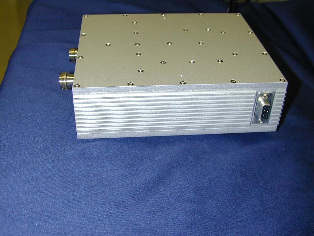
Click to zoom
Application Details
- Equipment Class
- AMP - Amplifier
- Date of Grant
- Jun 10, 2003
- Application Purpose
- Original Equipment
- Date of Application
- Jun 10, 2003
- Equipment Note
- Bi-Directional Amplifier
- Frequency Range
- 851.00850000 - 865.99150000
- Company
- Hankook Antenna Co., Ltd.
- Country
- South Korea
Documents & Files
Document Text
Text extracted from the exhibit documents filed with the FCC. Open a document above to read the original.
Users Manual
Model 100-AS SMR Band RF Repeater User’s Guide ExCell RF, Inc. 6400 Windcrest Drive Suite 1614 Plano, TX 75024 972-473-9988 www.excell-rf.com 2003 ExCell RF, Inc., all rights reserved ExCell RF Model 100-AS User's Guide-rev1.0 - 2 - April 3, 2003 Notice The information contained in this document is subject to change without notice. We make no warranty of any kind with regard to this material, including but not limited to, the implied warranties of merchantability and fitness for a particular purpose. We shall not be liable for errors contained herein or for incidental or consequential damages in connection with the furnishing, performance, or use of this material. Safety Information The following safety symbols are used throughout this manual. Familiarize yourself with the symbols and their meaning before operating this instrument. Warning: Warning denotes a hazard. It calls attention to a procedure, which if not correctly performed or adhered to, could result in injury or loss of life. Do not proceed beyond a warning note until the indicated conditions are fully understood and met. Caution: Caution denotes a hazard. It calls attention to a procedure that, if not correctly performed or adheres to, could result in damage to or destruction of the instrument. Do not proceed beyond a caution sign until the indicated conditions are fully understood and met. Note: Note calls out special information for the user’s attention. It provides operational information or additional instructions of which the user should be aware. Warning: No operator serviceable parts inside. Refer servicing to qualified personnel. Caution: Always use the three-prong AC power cord supplied with this product. Failure to ensure adequate grounding may cause product damage. ExCell RF Model 100-AS User's Guide-rev1.0 - 3 - April 3, 2003 Warranty This product is warranted against defects in material and workmanship for period of one year from date of shipment. During the warranty period, we will, at our option, either repair or replace products that prove to be defective. For warranty service or repair, this product must be returned to our designated service facility. Buyer shall prepay shipping charges for products returned to us and we shall pay shipping charges to return the repaired product to Buyer. However, Buyer shall pay all shipping charges, duties, and taxes for replacement of products in another country. We warrant this product when properly installed. We do not warrant that the operation of this product will be uninterrupted or error-free. Limitation of Warranty The foregoing warranty shall not apply to defects resulting from improper or inadequate maintenance by Buyer. Unauthorized modification or misuse, operation outside of the environmental specifications for the product, or improper site preparation or maintenance is also not covered by this warranty. NO OTHER WARRANTY IS EXPRESSED OR IMPLIED. WE SPECIFICALLY DISCLAIM THE IIMPLIED WARRANTIES OF MECHANTABILITY AND FITNESS FOR A PARTICULAR PRUPOSE. THIS EQUIPMENT COMPLIES WITH APPLICABLE FCC RULES. ANY CHANGES OR MODIFICATIONS NOT EXPRESSLY APPROVED BY THE MANUFACTURER COULD VOID THE USER’S AUTHORITY TO OPERATE THE EQUIPMENT. Caution: A minimum separation distance of 20cm between the transmit antenna and nearby persons must be maintained. If this separation distance is not maintained, this device may not be in compliance with FCC Exposure Rules. ExCell RF Model 100-AS User's Guide-rev1.0 - 4 - April 3, 2003 Contents 1. Overview................................................................................................................5 2. Preparation for Use...............................................................................................6 2.1. Initial Inspection.............................................................................................6 2.2. Power Requirements......................................................................................6 2.3. Turning On the Repeater...............................................................................7 2.4 Front View................................................................................................................7 3. Testing.....................................................................................................................8 3.1 Specifications.........................................................................................................8 3.2 Appearance Inspection........................................................................................8 3.3 MGC, Output Power & OIP3 Test...........................................................................9 3.3.1 Equipment......................................................................................................9 3.3.2 Criterion..........................................................................................................9 3.3.3 Equipment Setting.........................................................................................9 3.3.4 Test Procedures.............................................................................................9 3.4 Flatness, Time Delay, Isolation and VSWR Measurements..............................11 3.4.1 Equipment....................................................................................................11 3.4.2 Criterion........................................................................................................11 3.4.3 Equipment Setting.......................................................................................11 3.4.4 Test Procedures...........................................................................................11 3.5 AGC Test................................................................................................................12 3.5.1 Equipment....................................................................................................12 3.5.2 Criterion............…
Text truncated - open the document above for the full version.
ID Label/Location Info
Location of FCC Label
Operational Description
Technical Description Ñ Description In-door Repeater Expand the coverage, especially for inside buildings and basement. Ñ Type Full Duplex Type Ñ Frequency Range Down Link : 806MHz ~ 821MHz Up Load : 851MHz ~ 869MHz Ñ Max. Output Power +27dBm0.5dB (Nominal 0.5W) Max. Input Power –40dBm Ñ AGC 30dB MGC 20dB Ñ Power Supply 110V, 60Hz (US Only) Wireless Network Concept Drawing Inside Building Repeater In-Building ANT. Service Area BTS or Large Repeater Service Area Donor ANT.
Parts List/Tune Up Info
ExCell RF Model 100-AS User's Guide-rev1.1 - 9 - April 3, 2003 3.3 MGC, Output Power & OIP3 Test 3.3.1 Equipment Equipment Name Number Remarks Spectrum Analyzer 1 Agilent 8595E or the equivalent Signal Generator 2 Agilent E4432B or the equivalent 2-Way Combiner 1 General Purpose Power Attenuator 1 Over 30dB (For protection of measurer) Band Pass Filter (BPF) 1 For protection of measurer 3.3.2 Criterion MGC Range : 20dB Output Power : +27dBm0.5dB OIP3 : +45dBm(@14dBm/Tone) 3.3.3 Equipment Setting 30dB Power Attenuator BPF2Way 8595 E 3.3.4 Test Procedures l Common Measurement 1) Measures the path loss from the Signal Generator output to the Repeater input.( IN loss ) 2) Measures the path loss from the Repeater output to the Spectrum Analyzer input.( OUT loss ) 3) Set the apparatus as drawings above. Warning: The BPF is used to protect the Signal Generator and the 30dB Power Attenuator is used to protect the Spectrum Analyzer. 4) Set the Signal Generator output as (-46+IN loss )dBm, and frequency as ExCell RF Model 100-AS User's Guide-rev1.1 - 10 - April 3, 2003 860 MHz(@ Down link Case, 815MHz @ Uplink Case). 5) Set the Spectrum Analyzer as follows. [ RBW : 30KHz, VBW : 300Hz, SWP : AUTO, SPAN : 2MHz, CF : 860MHz Amplitude Offset : ( 30 + OUT loss ) dB ] l MGC and Output Power Measurement 1) Check the selection switch as MGC mode. 2) Turn off one of signal generators. 3) Connect the power cord of the repeater to the AC line. Warning: Use a 3-wire AC Line and check the line voltage. 4) Measure and confirm that the output power is 27dBm0.5dB. 5) Turning the variable resistor and measure gain variation. 6) Disconnect the power cord of the repeater to the AC line. 7) Repeat the same test to the Uplink frequency. MGC Gain Reference Table(Check 9 Pin D-Sub Pin 7 & 9) Gain Voltage Attenuation 70 dB - 3 dB 3.09 V 0 dB 65 dB 3 dB 1.31 V 5 dB 60 dB 3 dB 0.99 V 10 dB 55 dB 3 dB 0.83 V 15 dB 50 dB 3 dB 0.75 V 20 dB 40 dB 3 dB 0.63 V 30 dB Pin 7 is for Down Link, Pin 9 is for Up Link l OIP3 Measurement 1) Connect the power cord of the repeater to the AC line. 2) Set 2 Tone Spacing as 250KHz. 3) Set output power to +14dBm each tone. 4) Measure 3 rd harmonics value. 5) Calculate OIP3 using the following formula. OIP3 = Pout + IMD/2 6) Repeat the same test to the Uplink frequency.
RF Exposure Info
Prediction of MPE limit at a given distance Equation from page 18 of OET Bulletin 65, Edition 97-01 where:S = power density P = power input to the antenna G = power gain of the antenna in the direction of interest relative to an isotropic radiator R = distance to the center of radiation of the antenna Maximum peak output power at antenna input terminal:27.00(dBm) Maximum peak output power at antenna input terminal:501.1872(mW) Antenna gain(typical):7(dBi) Maximum antenna gain:5.011872(numeric) Prediction distance:20(cm) Prediction frequency:860(MHz) MPE limit for uncontrolled exposure at prediction frequency:0.533333(mW/cm^2) Power density at prediction frequency:0.499724(mW/cm^2) 2 4R PG S π =
Test Report
Nemko Test Report: 3L0083RUS1 Applicant: ExCell RF, Inc. 6400 Windcrest Drive Suite # 1226 Plano, TX 75024 Equipment Under Test: Model 100-AS (E.U.T.) SMR Band RF Repeater FCC ID: In Accordance With: FCC Part 90, Subpart I Private Land Mobile Repeater Tested By: Nemko Dallas Inc. 802 N. Kealy Lewisville, TX 75057-3136 Authorized By: Tom Tidwell, Frontline Manager Date: 5/16/03 Total Number of Pages: 37 Nemko Dallas FCC PART 90, SUBPART I PRIVATE LAND MOBILE REPEATER EQUIPMENT: 100-AS TEST REPORT NO.: 3L0083RUS1 Page 2 of 37 Table of Contents Section 1. Summary of Test Results.................................................................................................3 Section 2. General Equipment Specification......................................................................................5 Section 3. RF Power Output.............................................................................................................7 Section 4. Occupied Bandwidth........................................................................................................8 Section 5. Spurious Emissions at Antenna Terminals......................................................................13 Section 6. Field Strength of Spurious Emissions..............................................................................24 Section 7. Test Equipment List.......................................................................................................27 ANNEX A - TEST METHODOLOGIES............................................................................................28 ANNEX B - TEST DIAGRAMS.........................................................................................................34 Nemko Dallas FCC PART 90, SUBPART I PRIVATE LAND MOBILE REPEATER EQUIPMENT: 100-AS TEST REPORT NO.: 3L0083RUS1 Page 3 of 37 Section 1. Summary of Test Results Manufacturer: ExCell RF, Inc. Model No.: 100-AS Serial No.: None General: All measurements are traceable to national standards. These tests were conducted on a sample of the equipment for the purpose of demonstrating compliance with FCC Part 90, Subpart I. New Submission Production Unit Class II Permissive Change Pre-Production Unit A M P Equipment Code THIS TEST REPORT RELATES ONLY TO THE ITEM(S) TESTED. THE FOLLOWING DEVIATIONS FROM, ADDITIONS TO, OR EXCLUSIONS FROM THE TEST SPECIFICATIONS HAVE BEEN MADE. See “ Summary of Test Data”. Nemko Dallas Inc. authorizes the above named company to reproduce this report provided it is reproduced in its entirety and for use by the company’s employees only. Any use which a third party makes of this report, or any reliance on or decisions to be made based on it, are the responsibility of such third parties. Nemko Dallas Inc. accepts no responsibility for damages, if any, suffered by any third party as a result of decisions made or actions based on this report. This report applies only to the items tested. Nemko Dallas FCC PART 90, SUBPART I PRIVATE LAND MOBILE REPEATER EQUIPMENT: 100-AS TEST REPORT NO.: 3L0083RUS1 Page 4 of 37 Summary Of Test Data NAME OF TEST PARA. NO. SPEC. RESULT RF Power Output 90.205 500 Watts ERP Complies Audio Frequency Response TIA EIA-603.3.2.6 N/A N/A Audio Low-Pass Filter Response TIA EIA-603.3.2.6 N/A N/A Modulation Limiting TIA EIA-603.3.2.6 N/A N/A Occupied Bandwidth 90.210 Input/Output Complies Spurious Emissions at Antenna Terminals 90.210 50+10log(P) Watts (-20 dBm) Complies Field Strength of Spurious Emissions 90.210 50+10log(P) Watts (-20 dBm) Complies Frequency Stability 90.213 N/A Transient Frequency Behavior 90.214 N/A N/A Footnotes For N/A’s: (1) Since the E.U.T. does not contain modulation circuitry modulation testing was not performed. (2) Since the E.U.T. is not a keyed carrier system, Transient Frequency Behavior was not performed. . Nemko Dallas FCC PART 90, SUBPART I PRIVATE LAND MOBILE REPEATER EQUIPMENT: 100-AS TEST REPORT NO.: 3L0083RUS1 Page 5 of 37 Section 2. General Equipment Specification Transmitter Supply Voltage Input: 120 Vac Frequency Range: Uplink 806.0085 to 820.9915 MHz Downlink 851.0085 to 865.9915 MHz Tunable Bands: Type(s) of Modulation: F3E F1D F2D D7W (QAM) Other Maximum Input: -40 dBm (100μW) Output Impedance: 50 ohms RF Power Output (rated): Single: 27 dBm (501 mW) Composite: 17 dBm (50.1 mW) Channel Spacing(s): 25 kHz Operator Selection of Operating Frequency: None Power Output Adjustment Capability: Attenuators Frequency Translation: F1-F1 F1-F2 N/A Band Selection: Software Duplexer Change Fullband Coverage Nemko Dallas FCC PART 90, SUBPART I PRIVATE LAND MOBILE REPEATER EQUIPMENT: 100-AS TEST REPORT NO.: 3L0083RUS1 Page 6 of 37 Theory of Operation The Model 100-AS repeater is a compact, high-gain bi-directional amplifier that can be used to amplify RF signals in the 800 MHz SMR band. The Model 100-AS repeater can solve wireless coverage problems for most indoor and outdoor applications System Diagram Nemko Dallas FCC PART 90, SUBPART I PRIVATE LAND MOBILE REPEATER EQUIPMENT: 100-AS TEST REPORT NO.: 3L0083RUS1 Page 7 of 37 Section 3. RF Power Output NAME OF TEST: RF Power Output PARA. NO.: 2.985 TESTED BY: David Light DATE: 5/15/03 Test Results: Complies. Measurement Data: Frequency (MHz) Measured Power (dBm) Rated Power (dBm) Measured/Rated (dB) 815 27 dBm 27 dBm 1 860 27 dBm 27 dBm 1 Nemko Dallas FCC PART 90, SUBPART I PRIVATE LAND MOBILE REPEATER EQUIPMENT: 100-AS TEST REPORT NO.: 3L0083RUS1 Page 8 of 37 Section 4. Occupied Bandwidth NAME OF TEST: Occupied Bandwidth PARA. NO.: 2.989 TESTED BY: David Light DATE:5/15/03 Test Results: Complies. Test Data: See attached graph(s). Nemko Dallas FCC PART 90, SUBPART I PRIVATE LAND MOBILE REPEATER EQUIPMENT: 100-AS TEST REPORT NO.: 3L0083RUS1 Page 9 of 37 Test Plots – Occupied Bandwidth Dallas Headquarters: 802 N. Kealy Lewisville, TX 75057 Tel: (972) 436-9600 Fax: (972) 436-2667 Nemko Dallas, Inc. Data Plot Page 1 of7 Complete Job No.:3L0083R Date:5/15/2003Preliminary: Specification:PART …
Text truncated - open the document above for the full version.
Contact Information
Applicant
H. J Kim(President)
[email protected]82326765511
Technical Contact
Nemko DallasTom Tidwell
[email protected]972-436-9600
802 N. Kealy · Lewisville, Texas · United States
Non-Technical Contact
Nemko DallasDin Chauhan
[email protected]972-436-9600
Test Firm
Nemko Dallas, Inc.Michael Cantwell
Technical Specifications
| # | Rule Parts | Frequency Range | Power Output | Emission | Tolerance |
|---|---|---|---|---|---|
| 2 | 9 | 851.0085 MHz - 865.9915 MHz | 500.00 mW | F3E | Amp |