Q7LKAROZRF-001Security Wireless Sensor
Omni Key Technology Corp.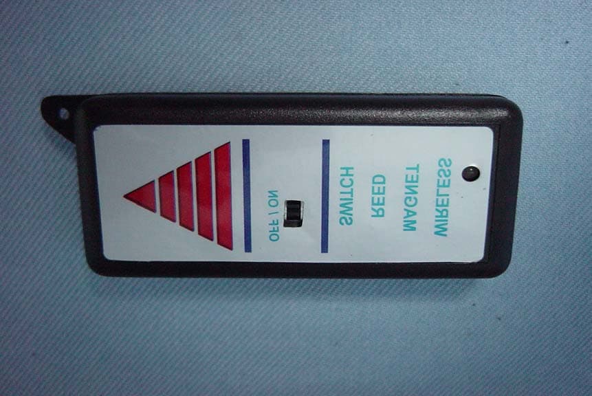
Click to zoom
Application Details
- Equipment Class
- DSC - Part 15 Security/Remote Control Transmitter
- Date of Grant
- May 29, 2003
- Application Purpose
- Original Equipment
- Date of Application
- May 29, 2003
- Equipment Note
- Security Wireless Sensor
- Frequency Range
- 433.92000000 - 433.92000000
- Company
- Omni Key Technology Corp.
- Country
- Taiwan
Documents & Files
Document Text
Text extracted from the exhibit documents filed with the FCC. Open a document above to read the original.
Users Manual
Security Auto Alarm ( K K a a r r o o z z I I - - 1 1 0 0 0 0 0 0) Manual Date: 2003.04.23 Version: 1 1 Content Content ................................................................................................................................................... 1 1. Inspection of the product and Enclosed Accessories ........................................................... 2 1.1 Include ......................................................................................................................................... 2 1.2 Specifications ............................................................................................................................ 2 2. Product Description ............................................................................................................. 2 2.1 Features ....................................................................................................................................... 2 3. Illustration and Functions .................................................................................................... 3 3.1 Product Appearance ............................................................................................................... 3 3.2 Functional Description .......................................................................................................... 3 4. Hardware Installation........................................................................................................... 4 4.1 Sensor Setup step by step ..................................................................................................... 4 4.2 Main Machine Setup .............................................................................................................. 4 2 1. Inspection of the product and Enclosed Accessories Please make sure your product package is fine, and if you discover any lost or break, please contact consignee. 1.1 Include z Auto Alarm 1 set z DC 12V Transformer 1 pcs (for 110V 60Mz) z Wireless Reed Sensor 4 pcs 1.2 Specifications z Power Input Connector: DC PLUG , 2.1 z Power supply: DC 12V , 0.5A z Power Consumption: Maximum Consumption , 2.5W z Dimension: 213(H)x142(W)x28(D) mm z Wireless Transmission frequency: UHF, 433.92MHz 2. Product Description When the Sensors are triggered, the Auto Alarm will alarm. So it supports the functions of real-time informing and responding. 2.1 Features z Eight Sensing: The Auto Alarm can receive the sensing signals of multi sets simultaneously. It would begin to act while detecting the triggered status. 3 3. Illustration and Functions 3.1 Product Appearance ` 1 2 5 3 4 6 11 10 7 3.2 Functional Description 1. 1~4 Sensor Action Light: When the sensor is exerted, the corresponding light will be on. 2. 5~8 Sensor Action Light: When the sensor is exerted, the corresponding light will be on. 3. Power light: When the power is connected, the light will be on. 4. Seven Segment Display: When the sensor is exerted, Seven Segment will display the number. 5. Power Jack: Jack for power connection. 6. Reset Button: When pressing this Button, system will restart. 7. Antenna: Main machine receiving. 4 4. Hardware Installation 4.1 Sensor Setup step by step Wireless: 1. Wireless Reed Sensor: (1) Insert the DC 12V battery. (2) When use the Wireless Reed Sensor, please push the switch to “ON”, it enters the standby. (3) If the magnetic iron is far away it, the LED changes the red color and transmits the message to the main machine. After two seconds, the power is off and it enters save power mode. (4) If the electric power of battery is low, the LED will show (red+green) color. Please change the battery. (5) If user want to change the set of sensor, please open the case and change the switch as below. It will cause the fail operation of system while wrong setting. Set Switch 1 2 3 4 5 6 7 8 1 Off Off On Off On Off On Off 2 On On Off Off On On Off Off 3 On On On On Off Off Off Off 4 Off On On On On On On On Caution: If use for long time and not turn OFF the sensor, please replace battery every three mouth. 4.2 Main Machine Setup 1. Connect DC 12V Transformer on Auto Alarm Power Jack. 2. Press Reset Button, restart system. 3. Proceed to System Setup. (Refer to system setup) When set up the Auto Alarm, let it be more than 70 cm far away ground. It must be far away electric product and conductor in order to disturb and reduce received sensitivity. Warranty Illustration F RAID WIZARD 1KI F RAID WIZARD 2KI F IDMS Argus 2016 F Smart Alarm F Security Auto Dialer J Security Auto Alarm F Car Rear View System 1. The product has an initial one-year warranty from the date of purchase. 2. If the equipment does not function properly during the warranty period due to defect in un-artificiality, OKTC will repair the equipment without charge. Only damage occurs as listed below, OKTC will charge maintenance or material cost. (The time spent to repair is based on circumstance of damage.) z The damage occurs due to the situation of natural loss, man-make or irresistible disaster. z The damage occurs during product shipment, drop, unusual voltage or improper install after purchased. z The damage occurs due to failure to follow user’s manual instruction. z Unauthorized modifications or service. 3. After warranty time period, the service as adjustment, upkeep or repair has to charge cost of maintenance, the cost will rise if the parts have to replace. Omni Key Technology Corp. ( ) No.74, ShangHai Rd., ChiaYi City, Taiwan 600, R.O.C. ( 74 ) Tel: 886-5-2839606 Fax: 886-5-2832482 Web Site: www.oktc.com.tw E-mail: [email protected] 15.21 Federal Communications Commission (FCC) Statement You are cautioned that changes or modifications not expressly approved by the part responsible for compliance could void the user’s authority to operate the equipment. 15.105(b) Federal Communications Commission (FCC) Statement This equipment has been tested and found to comply with the limits for a Class B …
Text truncated - open the document above for the full version.
Block Diagram
Wireless Reed Sensor Function Block Reed Power Encoder HF
External Photos
C&C Laboratory Co. Ltd. REPORT NO: 030070-R-ID ID: Q7LKAROZRF-001 DATE: May 26, 2003 Page 23 Rev. 00 APPENDIX 2 EXTERNAL PHOTOGRPHS OF EUT C&C Laboratory Co. Ltd. REPORT NO: 030070-R-ID ID: Q7LKAROZRF-001 DATE: May 26, 2003 Page 24 Rev. 00 Front View of TX Back View of TX
ID Label/Location Info
FCC ID LABEL FORMAT AND LOCATION Applicant: Omni Key Technology Corp. FCC ID: Q7LKAROZRF-001 FCC ID: Q7LKAROZRF-001 This device complies with part 15 of the FCC Rules. Operation is subject to the following two conditions: (1) This device may not cause harmful interference, and (2) this device must accept any interference received, including interference that may cause undesired operation. LABEL AREA
Internal Photos
C&C Laboratory Co. Ltd. REPORT NO: 030070-R-ID ID: Q7LKAROZRF-001 DATE: May 26, 2003 Page 25 Rev. 00 APPENDIX 3 INTERNAL PHOTOGRPHS OF EUT C&C Laboratory Co. Ltd. REPORT NO: 030070-R-ID ID: Q7LKAROZRF-001 DATE: May 26, 2003 Page 26 Rev. 00 Internal of TX --- 1 Internal of TX --- 2 C&C Laboratory Co. Ltd. REPORT NO: 030070-R-ID ID: Q7LKAROZRF-001 DATE: May 26, 2003 Page 27 Rev. 00 Internal of TX --- 3
Operational Description
Descriptionfor Secur ity Wir eless Sensor 1.Security Wireless Sensor consists of a magnetic iron and Reed-Switch circuit. 2.When Reed-Switch circuit is far away the magnetic iron, it transmits the RF signal (433MHz) that magnetic iron is not connected to Reed-Switch circuit. 3.WhenReed-Switch circuit isn’t far away magnetic iron, it is no power to transmit RF signal. (433MHz) 4.To take magnetic iron away Reed-Switch circuit, circuit will work in 2 second. 5.Sensor ID is identified from 4-Switch on circuit,you can choose it.It will access IC PT2262 to convert into encoded signal,and access “Crystal circuit and Transmit circuit” to convert into RF signal. 6.Security Auto Alarm System receives the sensor ID, and can know which sensor is touched. 7.The power of Security Wireless Sensor is based on DC12V Battery. 8.The device can be use as alarm for “car or home security”. Zeon PDF Driver Trial www.zeon.com.tw
Schematics
AR153.3M RF_TD4 RF_Signal RF_TD4 VCC VCC RF_TA4 ARA1xR AR111k AC8 5p ASW1Reed SW AR847k ARA12 1k ARB4xR AR131M PW_LED RF_TA5 RF_TD3 AR3 1k Q22N3904 RF_TA3 RF_TA6 AC6 xC AR176.2k VCC RF_TD2 AR4xR ARB2xR AC41n RF_TA8 RF_TD1 AC5100p Wireless Reed Sensor V2.2 Auto Informer Omni Key Technology Corporation 11 Tuesday, May 06, 2003 TitleSize Document Number Rev Date: Sheet of RF_TA8 AC102.2u AR161k RF_TA3 RF_TA2 RF_TD1 B+ AR2100 VCC VCC AC13 xC RF_TA7 ARA11 1k AR1910k AR103.3M AC12 0.1u ON 1234 ASW3SW DIP-4 AR184.7k ARB8xRARB5xR RF_TA6 ARB6xR AC145p AJ1Battery CON 12 ARA7xR ASW2 ACTIVE SW 1 2 3 RF_TA5 AU3 UTC8150 3 1 2 GND VCC Vout AE2ANT2 12 ARB1xR ARA5xR RF_TA4 ARB7xR RF_TD2 AD1 LED 2C AR9220 RF_TA2 RF_TD3 ARA10 1k AU2PT2262 123456789 181716151413121110 A0A1A2A3A4A5A6/D5A7/D4Vss Vcc Dout OSC2OSC1 /TE A11/D0A10/D1 A9/D2A8/D3 VCC Q12N7002 ARA8xR ARB3xR PW_LED VCC AR1470 VCC B- AY1 SAW V+ AR14 1k AC20.1u RF_TA7 ARA6xR ARA9 1k AL26.8nHAQ32SC3356 ARA3xR RF_TA1 RF_TA1 AR121k ARA2xR
Test Report
C&C Laboratory Co. Ltd. REPORT NO: 030070-R-ID ID: Q7LKAROZRF-001 DATE: May 26, 2003 Page 1 of 26 Rev. 00 ELECTROMAGNETIC EMISSIONS COMPLIANCE REPORT INTENTIONAL RADIATOR CERTIFICATION TO FCC PART 15 SUBPART C REQUIREMENT OF Security Wireless Sensor Model Name: Security RF-001 Brand Name: OKTC FCC ID: Q7LKAROZRF-001 REPORT NO: 030070-R-ID ISSUE DATE: May 26, 2003 Prepared for Omni Key Technology Corp. No. 74, Shanghai Rd., Chiayi City, Taiwan, R.O.C. Prepared by C&C LABORATORY, CO., LTD. No. 81-1, Lane 210, Bade Rd. 2, Luchu Hsiang, Taoyuan Hsien, Taiwan. TEL: 886-3-3240332 FAX: 886-3-3245235 This report shall not be reproduced, except in full, without the written approval of C&C Laboratory, Co., Ltd. C&C Laboratory Co. Ltd. REPORT NO: 030070-R-ID ID: Q7LKAROZRF-001 DATE: May 26, 2003 Page 2 Rev. 00 VERIFICATION OF COMPLIANCE Applicant: Omni Key Technology Corp. No. 74, Shanghai Rd., Chiayi City, Taiwan, R.O.C. Product Description: Security Wireless Sensor Brand Name: OKTC Model No.: Security RF-001 Serial Number: N/A File Number: 030070-R-ID Date of test: May 16 ~ 19, 2003 We hereby certify that: The above equipment was tested by C&C Laboratory Co., Ltd. The test data, data evaluation, test procedures, and equipment configurations shown in this report were made in accordance with the procedures given in ANSI C63.4 (1992) and the energy emitted by the sample EUT tested as described in this report is in compliance with conducted and radiated emission limits of FCC Rules Part 15.231. The test results of this report relate only to the tested sample identified in this report. Approved By Review By Jonson Lee / Director Susan Su / Section Manager C&C Laboratory Co., Ltd. C&C Laboratory Co., Ltd. C&C Laboratory Co. Ltd. REPORT NO: 030070-R-ID ID: Q7LKAROZRF-001 DATE: May 26, 2003 Page 3 Rev. 00 Table of Contents 1. GENERAL INFORMATION ................................................................................................ 4 1.1 P RODUCT D ESCRIPTION ..........................................................................................................................4 1.2 R ELATED S UBMITTAL ( S ) / G RANT ( S ).....................................................................................................4 1.3 T EST M ETHODOLOGY ..............................................................................................................................4 1.4 T EST F ACILITY ........................................................................................................................................4 1.5 S PECIAL A CCESSORIES ............................................................................................................................4 1.6 E QUIPMENT M ODIFICATIONS ..................................................................................................................4 2. SYSTEM TEST CONFIGURATION ................................................................................... 5 2.1 EUT C ONFIGURATION .............................................................................................................................5 2.2 EUT E XERCISE ........................................................................................................................................5 2.3 T EST P ROCEDURE ....................................................................................................................................5 2.4 L IMITATION .............................................................................................................................................6 2.4 C ONFIGURATION OF T ESTED S YSTEM .....................................................................................................7 3. SUMMARY OF TEST RESULTS ........................................................................................ 8 4. DESCRIPTION OF TEST MODES ..................................................................................... 8 5. AC POWER LINE CONDUCTED EMISSION TEST ....................................................... 9 5.1 EUT S ETUP .............................................................................................................................................9 5.2 M EASUREMENT P ROCEDURE ...................................................................................................................9 5.3 M EASUREMENT E QUIPMENT U SED : ........................................................................................................9 5.4 M EASUREMENT R ESULT .........................................................................................................................9 6. RADIATED EMISSION TEST ........................................................................................... 10 6.1 M EASUREMENT P ROCEDURE .................................................................................................................10 6.2 T EST SET-UP (B LOCK D IAGRAM OF C ONFIGURATION ) .......................................................................11 6.3 M EASUREMENT E QUIPMENT U SED : ......................................................................................................12 6.4 F IELD S TRENGTH C ALCULATION ..........................................................................................................12 6.5 M EASUREMENT R ESULT .......................................................................................................................12 7. OCCUPIED BANDWIDTH................................................................................................. 15 7.1 M EASUREMENT P ROCEDURE .................................................................................................................15 4. S ET SPA M AX HOLD . M ARK PEAK , -20 D B ...........................................................................................15 7.2 T EST S ETUP : .....................................................................................…
Text truncated - open the document above for the full version.
Test Setup Photos
C&C Laboratory Co. Ltd. REPORT NO: 030070-R-ID ID: Q7LKAROZRF-001 DATE: May 26, 2003 APPENDIX 1 PHOTOGRPHS OF SET UP C&C Laboratory Co. Ltd. REPORT NO: 030070-R-ID ID: Q7LKAROZRF-001 DATE: May 26, 2003 Radiated Emission Set up Photos
Contact Information
Applicant
Chao-Shu Liu(General Manager)
Test Firm
Compliance Certification Services Inc.Kurt Chen
Technical Specifications
| # | Rule Parts | Frequency Range | Power Output |
|---|---|---|---|
| 1 | 15.231 | 433.92 MHz - 433.92 MHz | - |