Q8603010Wireless Security System Camera Transmitter
Marasst Incorporation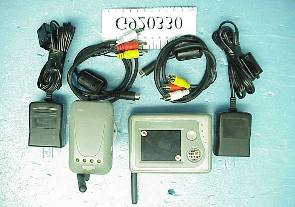
Click to zoom
Application Details
- Equipment Class
- DXX - Part 15 Low Power Communication Device Transmitter
- Date of Grant
- Jul 27, 2003
- Application Purpose
- Original Equipment
- Date of Application
- Jul 27, 2003
- Equipment Note
- Wireless Security System Camera Transmitter
- Frequency Range
- 2410.00000000 - 2470.00000000
- Company
- Marasst Incorporation
- Country
- Taiwan
Documents & Files
Document Text
Text extracted from the exhibit documents filed with the FCC. Open a document above to read the original.
Users Manual
Guardian Angel GA-251 Wireless Security System User's Manual Marasst.book Page 1 Thursday, June 19, 2003 6:05 PM Marasst.book Page 2 Thursday, June 19, 2003 6:05 PM Guardian Angel GA-251 Wireless Security System User's Manual Marasst.book Page 1 Thursday, June 19, 2003 6:05 PM Copyright Copyright © 2003 Marasst Corporation. All rights reserved. Trademarks All trademarks and registered trademarks are the property of their respective owners. Precautions When using the Guardian Angel, refer to the following instructions: •Read and follow all instructions and warnings provided. •Save these instructions for future use. •When servicing or replacement parts are required, ensure work is done by a qualified technician. •Do not use this unit near water or in a wet or damp environment. Any electrical equipment is hazardous if handled improperly. Ensure that you follow the preceding safety instructions to avoid harm to your- self and damage to the unit. Marasst.book Page 2 Thursday, June 19, 2003 6:05 PM FEDERAL COMMUNICATIONS COMMISSION INTERFERENCE STATEMENT This equipment has been tested and found to comply with the limits for a class B digital device, pursuant t Part 15 of the FCC Rules. These limits are designed to provide reasonable protection against harmful interfer- ence in a residential installation. This equipment generates, uses and can radiate radio frequency energy and, if not installed and used in accord- ance with and instructions, may cause harmful interference to radio communications. However, there is no guarantee that interference will not occur in a particular installation. If this equipment does cause harm- ful interference to radio or television reception, which can be determined by turning the equipment off and on, the user is encouraged to try to cor- rect the interference try one or more off the following measures: •Reorient or relocate the receiving antenna. •Increase the separation between the equipment and receiver. •Connect the equipment into an outlet on a circuit different from that to which the receiver is connected. •Consult the dealer or an experienced radio/TV technician for help. Caution: To assure continued FCC compliance: Any changes or modifications not expressly by the grantee of this device could void the user’s authority to operate the equipment. Marasst.book Page 3 Thursday, June 19, 2003 6:05 PM Table of Contents Introduction Features ................................................................................................................... 1 Unpacking ................................................................................................................ 2 Components ............................................................................................................. 3 Setting Up the Guardian Angel Setting Up the Camera/Transmitter ....................................................................... 5 Setting Up the Tripod ................................................................................ 6 Attaching the Camera to the Tripod ................................................................... 6 Positioning the Tripod ........................................................................................ 6 Setting Up the Fixed Mounting Bracket .................................................... 8 Assembling the Fixed Mounting Bracket ............................................................ 8 Attaching the Camera to the Angle Bracket ....................................................... 9 Attaching the Mounting Bracket to a Fixed Surface ........................................... 9 Setting Up the Video Monitor/Receiver ................................................... 11 Using the Batteries and Adapters ........................................................................ 12 Turning the Power On ............................................................................. 12 Using the Rechargeable Batteries .......................................................... 13 Recharging the Batteries ........................................................................ 14 Using the Power Adapters ...................................................................... 15 Plugging In the Power Adapters ....................................................................... 15 Using the Guardian Angel Using the Guardian Angel as a Wireless Audio/Video Security System .......... 16 Setting Channels ..................................................................................... 16 Setting Channels for Single Camera Use ......................................................... 16 Setting Channels for Multiple Camera Use ...................................................... 17 Adjusting the Focus ................................................................................ 18 Adjusting the Volume .............................................................................. 19 Connecting to a Television, VCR or External Monitor ............................. 20 Using the Guardian Angel as a Wireless Audio/Video Center .......................... 22 Making Connections ............................................................................... 22 Connecting the Transmitter .............................................................................. 22 Connecting the Receiver .................................................................................. 23 Turning On the Power (A/V Center Mode) .............................................. 24 Setting Up Channels for A/V Center Use ................................................ 25 Recording on a VCR ............................................................................... 25 Adjusting Reception Quality .................................................................... 25 Specifications ........................................................................................................ 26 Troubleshooting ..................................…
Text truncated - open the document above for the full version.
Block Diagram
Page 20 Marasst Inc. Wireless Security System (Camera/Transmitter) FCC ID. : Q8603010 Block Diagram
Cover Letter(s)
Page 3 Marasst Inc. Wireless Security System (Camera/Transmitter) FCC ID. : Q8603010 Date: Jun. 16, 2003 Subject : RFI related modifications incorporated into unit with FCC ID. : Q8603010 Dear Sir, This letter services as our declaration that all modifications listed below are implemented in the sample submitted for pre-grant testing. We further declare that the same modifications will be implemented into all production unit to enhance compliance of the unit to FCC limits. The modifications include the following : 1. Add a ferrite core with one turn on the power cord. @ Refer to Figure 1. (Page 7) 2. Add a ferrite core with one turn on the data cable (AV/S-Video). @ Refer to Figure 2. (Page 7.) If you have any questions or require any other information please do not hesitate to contact our agent. Sincerely Yours, Manager Marasst Inc.
Cover Letter(s)
From: Mike Kuo Sent: Tuesday, July 08, 2003 5:55 PM To: 'Audix\(??\)???' Subject: FW: Marasst Inc., FCC ID:Q8603010, AN03T3036 Dear Mike, > > Attached files are supplementary data > 1. Report & middle channel test data (attcahed to the origianl report - page > 23 & paage24). > 2. Operational description & schematic diagram. > > Please kindly process this project. > > Thanks & Best Regards > Monica Chang > -----Original Message----- From: CERTADM Sent: Tuesday, July 08, 2003 5:54 PM To: '[email protected]' Subject: Marasst Inc., FCC ID:Q8603010, AN03T3036 Notice_content ------------- Question #1: This transmitter is capable of operating from 2410-2470MHz. Per section 15.31(m) of FCC rules, three channels at low, middle and high channel shall be investigated up to 10th harmonics. The test report submitted only included low and high channel, please provide middle channel test data. Question #2: Please provide operational description per section 2.1033(b)(4) of FCC rules. Question #3: Please provide schematic diagram. Best Regards Mike Kuo The items indicated above must be submitted before processing can continue on the above referenced application. Failure to provide the requested information within 60 days of the original e-mail date may result in application dismissal and forfeiture of the filing fee. Also, please note that partial responses increase processing time and should not be submitted. Any questions about the content of this correspondence should be directed to the e-mail address listed below the name of the sender.
External Photos
Page 7 Marasst Inc. Wireless Security System (Camera/Transmitter) FCC ID. : Q8603010 Photographs Photo 1 Camera/Transmitter & Receiver & Power Adapters & AV/S-Video Cables Photo 2 Camera/Transmitter- General Appearance (Front View) 1. 2. Page 8 Marasst Inc. Wireless Security System (Camera/Transmitter) FCC ID. : Q8603010 Photo 3 Camera/Transmitter- General Appearance (Bottom View) Photo 4 Camera/Transmitter- General Appearance (Rear View)
ID Label/Location Info
Page 5 Marasst Inc. Wireless Security System (Camera/Transmitter) FCC ID. : Q8603010 Label Drawing l Label Placement Location (Back Side of EUT) FCC LABEL FCC ID.: Q8603010 This device complies with Part 15 of the FCC Rules. Operation is subject to the following two conditions: (1) This device may not cause harmful interference, and (2) this device must accept any interference received, including interference that may cause undesired operation.
Internal Photos
Page 9 Marasst Inc. Wireless Security System (Camera/Transmitter) FCC ID. : Q8603010 Photo 5 Camera/Transmitter- Internal View (Removed Case) Photo 6 Camera/Transmitter- Internal View (Removed Battery & Control Board) Page 10 Marasst Inc. Wireless Security System (Camera/Transmitter) FCC ID. : Q8603010 Photo 7 Camera/Transmitter- TX Main Board (Foil Side) Photo 8 Camera/Transmitter- TX Main Board (Component Side) Page 11 Marasst Inc. Wireless Security System (Camera/Transmitter) FCC ID. : Q8603010 Photo 9 Camera/Transmitter- TX Main Board (Component Side, Removed Metal Cove r) Photo 10 Camera/Transmitter- TX Main Board (Component Side, Removed TX Module) Page 12 Marasst Inc. Wireless Security System (Camera/Transmitter) FCC ID. : Q8603010 Photo 11 Camera/Transmitter- TX Module (Component Side) Photo 12 Camera/Transmitter- TX Module (Foil Side) Page 13 Marasst Inc. Wireless Security System (Camera/Transmitter) FCC ID. : Q8603010 Photo 13 Camera/Transmitter- CMOS Sensor Board (Component Side) Photo 14 Camera/Transmitter- CMOS Sensor Board (Foil Side) Page 14 Marasst Inc. Wireless Security System (Camera/Transmitter) FCC ID. : Q8603010 Photo 15 Power Adapter (Front View) Photo 16 Power Adapter (Rear View) Page 15 Marasst Inc. Wireless Security System (Camera/Transmitter) FCC ID. : Q8603010 Photo 17 Power Adapter (Removed Case, Control Board, Component Side) Photo 18 Power Adapter (Control Board, Foil Side)
Operational Description
Circuit operation description: 1. CMOS & Microphone module (Attached schematic page 1 of 3): (1) OV7910 is a single-chip CMOS color NTSC/PAL camera working frequency is 14.318MHz. The array size is 510 x 492 pixels for NTSC. Operation in +5V +/- 5% power supply. (2) Y1 is a 14.318MHz crystal that connected to U1 OV7910 and provided the clock for U1. The internal frequency of U1 is 14.318MHz / 4 to meet NTSC subcarrier standards. (3) X1 is a high sensitive microphone. It is transfer sound/voice to electrical signal. (4) U2 is a low power dual operation amplifier which provided audio amplify function from X1(Microphone). The working voltage is +5V +/- 5%. 2. RF module & Power Supply(Attached schematic page 2 & 3): (1) Page 2, U6 PI5V331 is a wideband video Mux/Demux. There are two signal channels, one is from CMOS sensor and the other is from external device. U6 will change the output automatically by AV cable exist or not. (2) Page 3, U1 U2 U5 Q1 Q4 D12 are the key components of power supply for this module. It provided battery trickle charge, step-up from 2.4V battery to +5.2V, +5V & +3.3V low dropout regulator. (3) Page 3, TX1 VMT15T/D is a 2.4GHz A/V module use FM modulation technology to provide ISM band video and audio transmission. The operation voltage is +3.3V +/-0.05V. (4) The antenna port impedance is 50ohm for TX1 module. (5) 3mm-wide microstrip line is 50 ohm under 1.6mm FR-4 PCB. Microstrip is a transmission line on PCB with grounded backside. Since the placement and routing limitation, it is difficult to meet above policy. Base on the PCB antenna port real impedance, the antenna vendor adjusted its impedance to meets the specification for PCB trace and requirement of RF module.
Schematics
5 5 4 4 3 3 2 2 1 1 DD CC BB AA Micro phone Amp(optional) Marasst Incorporation As close to 7910 as possible MAKE A SIGNAL CONNECTION CLOSE TO REGULATOR OUTPUT OPTION: PLEASE KEEP IT IN LAYOUT, FOR NAY FURTHER QUALITY IMPROVEMENT 1. U1 OV7910 single-chip cmos color NTSC/PAL camera. Work frequence is (clock in)/4. 2. Y1 Frequence is NTSC 14.31818MHz/ PAL 17.734475MHz. 3. U2 LM358 low power dual operational amplifiers. Micphone signal amplifier. MWC_TX_0C2C2 BABY MONITOR - CMOS SENSOR B 11Friday, July 11, 2003 Title SizeDocument NumberRev Date:Sheet of SCL SDA VREF1 VCBRT BPAVE RSVD5 COLOR BW RSVD11 SMTAWB I2CEN FSO COLOR VCBRT BPAVE RSVD5 RSVD11 SMTAWB AUDIO1 GND_MIC GND VREF1 +5V AUDIO1 GND VCO VCO AVDD DVDD DVDD DVDD DVDD DVDD +5V DVDD AVDD AVDD MICVCC MICVCC MICVCC AVDD AVDD AVDD AVDD R17 N/A 1 2 R27 N/A 1 2 R33 7.5K R11N/A 12 R51M 12 X1 MICROPHONE R37 100K R9 10K 1 2 C16 .01UF R40200K + C15 10UF/10V 1 2 C20 2200PF C18 0.1UF R6 10K 1 2 R32100 12 C5 N/A R350 12 R110 12 R36 100K L1 0 + PC3 10UF/10V 1 2 C6 0.1UF C19 0.1UF C13 0.1UF R29 N/A 1 2 R24 N/A 1 2 R10 N/A 1 2 R16N/A 12 R31 N/A 1 2 R397.5K J1 85205-0400 1 2 3 4 R7 N/A 1 2 R26 N/A 1 2 R19 10K_OP 1 2 U2A LM358 8 3 2 4 1C11 0.1UF R23 10K 1 2 R41 75_OP 1 2 C1 33P C10 0.1UF Y1 14.318Mhz C12 .01UF C7 0.1UF + PC1 10UF/10V 1 2 R2N/A 12 C17 0.1UF C9 0.1UF R14 N/A 12 R18 N/A 1 2 TP2 R21 N/A 1 2 R30 N/A 1 2 R13N/A 12 R15N/A 12 R2210K 12 TP1 R25 N/A 1 2 C4 0.1UF U2B LM358 8 5 6 4 7 R38 7.5K R20 N/A 1 2 R28 N/A 1 2 R4N/A12 C8 0.1UF R310 12 C14 0.1UF C2 33P R8 4.7K_OP 1 2 OV7910/OV7410 U1 123456 7 8 9 10 11 12 13 14 15 16 17 18 192021222324252627282930 31 32 33 34 35 36 37 38 39 40 41 42 434445464748 SGNDSVDDVcBRTBPAVERsvd5AGND AVDD RGSW CEXP HSAT RGAMMA SMTawb EVDD EGND BUCO GYYO RVCVO OVDD G2X HGAIN BKLT XCLK1XCLK2 Reserve DVDDDGND GAMMA AGCEN AWBENAWBTM VAXPXO VHSYNC/MIR FSO/VSFR FODD/SBB Reserve1 FSI PWDN AMOD09= AMOD1 HSHP DEVDD DEGNZD SIO-1SIO-0VREF1VREF2VREF3VREF4 R340 12 5 5 4 4 3 3 2 2 1 1 DD CC BB AA Marasst Incorporation 1. U6 is Internal and External signal select. 2. Con1 is External signal input. 3. J3 connect to Txc board. GA_TX_C3C3 BABY MONITOR - CONNECTOR A 12Monday, July 14, 2003 Title SizeDocument NumberRev Date:Sheet of VIDEO E-IN-EN AUDL E-IN-EN C-IN AUDIO2 AUDIO1 VIDEO +5V MIC VCO MIC MIC C-IN AUDR GND AUDR AUDL PIN5 PIN6 PIN7 VCC +5V 12 345 678 CON1 Minidin-8/LNB0509E-8S 1 2 3 4 5 6 7 8 1 2 3 4 5 6 7 8 EN G1 1 1 MUX U6 FSAV330/TSSOP 15 1 2 3 5 6 11 10 14 1312 9 7 4 R16 4.7K J3 85205-0400 1 2 3 4 C13 0.1UF C12 0.1UF 5 5 4 4 3 3 2 2 1 1 DD CC BB AA 3V/0.21A 4V/0.15A 5V/0.11A 5.5V/0.1A 2.4V/0.24A +5.2V Marasst Incorporation 1. TX1 RF transmitter module, work frequence is 2.4GHz A/V modules use FM modulation technology to provide ISM band wireless audio and video connection. GA_TX_C3C3 BABY MONITOR - DC/DC & CHARGER B 22Monday, July 14, 2003 Title SizeDocument NumberRev Date:Sheet of VCO AUDIO1 AUDIO2 VIN PIN7 PIN6 PIN5 +3V +3V +5V +5.2V D9 ZD1 ZMM55C-5V6 Q3 2N2222 D2 FM240 D17 MCL4148 R15 510K + C7 220UF/6.3V + C3 100UF/16V Q2 2N7002 1 3 2 R20 0 R1920K R10100K U1 RT9161-50CX 2 1 3 VIN GND VOUT U2 RT9161-33CX 2 1 3 VIN GND VOUT R14 1.6M D10 BT1 Ni-Mh 2.4V D15 MCL4148 SW2 1 2 R11 470K D18 MCL4148 + C8 220UF/6.3V D12 FM240 + C5 220UF/6.3V D16 MCL4148 + C1 220UF/6.3V Q4 FDN306P 1 32 D11 C2 0.1UF R13 330 TX1 VMT15T/D 1 2 3 4 5 6 7 8 9 10 12 11 LED_CH1 LED_CH2 LED_CH3 SW LED_CH4 3V VIDEO GND AUDIO1 AUDIO2 GND ANT U5 RT9263CCX5 1 2 5 4 3 CE VDD GND LX FB C15 0.1UF T1 FILTER 1 4 3 6 R3 100_1/2W D13 MCL4148 + C9 220UF/6.3V SW1 SS058-PTA2230C-PA2 R17100K C4 0.1UF D14 MCL4148 C10 0.1UF C14 0.1UF ANT1 ANTENNA D8 R4 100_1/2W L14.7UH J1 MJC-003-A 1 2 3 Q1 FDN306P 1 32 C11 0.1UF C6 0.1UF R18100K R1 100K D1FM240 Circuit operation description: 1. CMOS & Microphone module (Attached schematic page 1 of 3): (1) OV7910 is a single-chip CMOS color NTSC/PAL camera working frequency is 14.318MHz. The array size is 510 x 492 pixels for NTSC. Operation in +5V +/- 5% power supply. (2) Y1 is a 14.318MHz crystal that connected to U1 OV7910 and provided the clock for U1. The internal frequency of U1 is 14.318MHz / 4 to meet NTSC subcarrier standards. (3) X1 is a high sensitive microphone. It is transfer sound/voice to electrical signal. (4) U2 is a low power dual operation amplifier which provided audio amplify function from X1(Microphone). The working voltage is +5V +/- 5%. 2. RF module & Power Supply(Attached schematic page 2 & 3): (1) Page 2, U6 PI5V331 is a wideband video Mux/Demux. There are two signal channels, one is from CMOS sensor and the other is from external device. U6 will change the output automatically by AV cable exist or not. (2) Page 3, U1 U2 U5 Q1 Q4 D12 are the key components of power supply for this module. It provided battery trickle charge, step-up from 2.4V battery to +5.2V, +5V & +3.3V low dropout regulator. (3) Page 3, TX1 VMT15T/D is a 2.4GHz A/V module use FM modulation technology to provide ISM band video and audio transmission. The operation voltage is +3.3V +/-0.05V. (4) The antenna port impedance is 50ohm for TX1 module. (5) 3mm-wide microstrip line is 50 ohm under 1.6mm FR-4 PCB. Microstrip is a transmission line on PCB with grounded backside. Since the placement and routing limitation, it is difficult to meet above policy. Base on the PCB antenna port real impedance, the antenna vendor adjusted its impedance to meets the specification for PCB trace and requirement of RF module.
Test Report
FCC ID.Q8603010 Page 1 of 22 Audix Corporation Report No. TTEMC-F92122 APPLICATION FOR CERTIFICATION On Behalf of Marasst Inc. Wireless Security System (Camera/Transmitter) Product Name : Guardian Angel Model : GA-251 FCC IDQ8603010 Prepared for : Marasst Inc. 104, 8F., No. 49, Sec. 3, Minsheng E. Rd., Taipei, Taiwan, R.O.C. Prepared By : Audix Corporation Technical Division EMC Department No. 53-11, Tin-Fu Tsun, Lin-Kou, Taipei Hsien, Taiwan, R.O.C. Tel : (02) 2609-9301, 2609-2133 Fax : (02) 2609-9303 File Number EM-G920330 Report Number TTEMC--F92122 Date of Test Apr. 17 ~ May 12, 2003 Date of Report Jun. 16, 2003 FCC ID.Q8603010 Page 2 of 22 Audix Corporation Report No. TTEMC-F92122 TABLE OF CONTENTS Description Page TEST REPORT CERTIFICATION.........................................................................................................3 1.GENERAL INFORMATION...............................................................................................................4 1.1.Description of Device (EUT).........................................................................................................4 1.2.Tested Supporting System Details.................................................................................................5 1.3.Description of Test Facility............................................................................................................5 1.4.Measurement Uncertainty..............................................................................................................5 2.POWERLINE CONDUCTED EMISSIION MEASUREMENT........................................................6 2.1.Test Equipment..............................................................................................................................6 2.2.Block Diagram of Test Setup.........................................................................................................6 2.3.AC Power Line Conducted Limits ((§15.207, Class B)................................................................6 2.4.EUT’s Configuration during Compliance Measurement...............................................................7 2.5.Operating Condition of EUT.........................................................................................................7 2.6.Test Procedure................................................................................................................................8 2.7.Line Conducted RF Voltage Measurement Results.......................................................................9 3.RADIATED EMISSION MEASUREMENT.....................................................................................11 3.1.Test Equipment............................................................................................................................11 3.2.Block Diagram of Test Setup.......................................................................................................11 3.3.Radiated Emission Limits [§15.249 (d)]......................................................................................12 3.4.Radiated Emission Limits [§15.249 (a)]......................................................................................12 3.5.EUT‘s Configuration during Compliance Measurement.............................................................12 3.6.Operating Condition of EUT.......................................................................................................13 3.7.Test Procedure..............................................................................................................................13 3.8.Radiated Emission Measurement Results....................................................................................14 4.DEVIATION TO TEST SPECIFICATIONS.....................................................................................18 5.MODIFICATON TO EUT.................................................................................................................19 6.PHOTOGRAPHS...............................................................................................................................20 6.1.Photos of Powerline Conducted Measurement............................................................................20 6.2.Photos of Radiated Measurement at Semi-Anechoic Chamber...................................................21 FCC ID.Q8603010 Page 3 of 22 Audix Corporation Report No. TTEMC-F92122 TEST REPORT CERTIFICATION Applicant Marasst Inc. Manufacturer Marasst Inc. EUT Description Wireless Security System (Camera/Transmitter) (A) PRODUCT NAME. Guardian Angel (B) MODEL NO. GA-251 (C) POWER SUPPLY DC 10V (via Adapter) DC 2.4V (Battery) (D) TEST VOLTAGE AC 120V/60Hz (via Adapter) Measurement Procedure Used: FCC RULES AND REGULATIONS PART 15 SUBPART C Section 15.249, MAY 2002 AND ANSI C63.4/1992 The device described above was tested by Audix Corporation to determine the maximum emission levels emanating from the device. The maximum emission levels were compared to the FCC Part 15 subpart C limits both radiated and conducted emissions. The measurement results are contained in this test report and Audix Corporation is assumed full responsibility for the accuracy and completeness of these measurements. Also, this report shows that the EUT to be technically compliant with the FCC official limits. This report applies to above tested sample only. This report shall not be reproduced in part without written approval of Audix Corporation. Date of Test : Apr. 17 ~ May 12, 2003 Prepared by : (Monica Chang/Assistant) Test Engineer : (Ben Cheng/Assistant Manager) Approve & Authorized Signer : (Leon Liu/Manager) FCC ID.Q8603010 Page 4 of 22 Audix Corporation Report No. TTEMC-F92122 1. GENERAL INFORMATION 1.1. Description of Device (EUT) Description Wireless Security System (Camera/Transmitter) Product Name Guardian Angel Model Number GA-251 FCC ID Q8603010 Applicant Marasst Inc. 104, 8F., No. 49, Sec…
Text truncated - open the document above for the full version.
Test Setup Photos
FCC ID.Q8603010 Page 20 of 22 Audix Corporation Report No. TTEMC-F92122 6. PHOTOGRAPHS 6.1. Photos of Powerline Conducted Measurement FRONT VIEW OF CONDUCTED MEASUREMENT SIDE VIEW OF CONDUCTED MEASUREMENT FCC ID.Q8603010 Page 21 of 22 Audix Corporation Report No. TTEMC-F92122 6.2. Photos of Radiated Measurement at Open Field Test Site 6.2.1. Frequency range 30MHz to 1000MHz FRONT VIEW OF RADIATED MEASUREMENT BACK VIEW OF RADIATED MEASUREMENT FCC ID.Q8603010 Page 22 of 22 Audix Corporation Report No. TTEMC-F92122 6.2.2. Frequency range above 1GHz FRONT VIEW OF RADIATED MEASUREMENT BACK VIEW OF RADIATED MEASUREMENT
Contact Information
Applicant
Billie Ho(R & D Manager)
Test Firm
Audix Technology CorporationJeff Chen
Technical Specifications
| # | Rule Parts | Frequency Range | Power Output |
|---|---|---|---|
| 1 | 15C | 2.41 GHz - 2.47 GHz | - |
Other Applications from Marasst Incorporation
Q8605001
May 02, 2005Wireless Care
Equipment Class
DXX - Part 15 Low Power Communication Device Transmitter
Q8604010
Apr 18, 2004Low Power FM Broadcast Transceiver
Equipment Class
DXX - Part 15 Low Power Communication Device Transmitter