Q8KBDALTEUC3390CUpper C LTE Bi Directional Amplifier
G-Way Solutions, LLC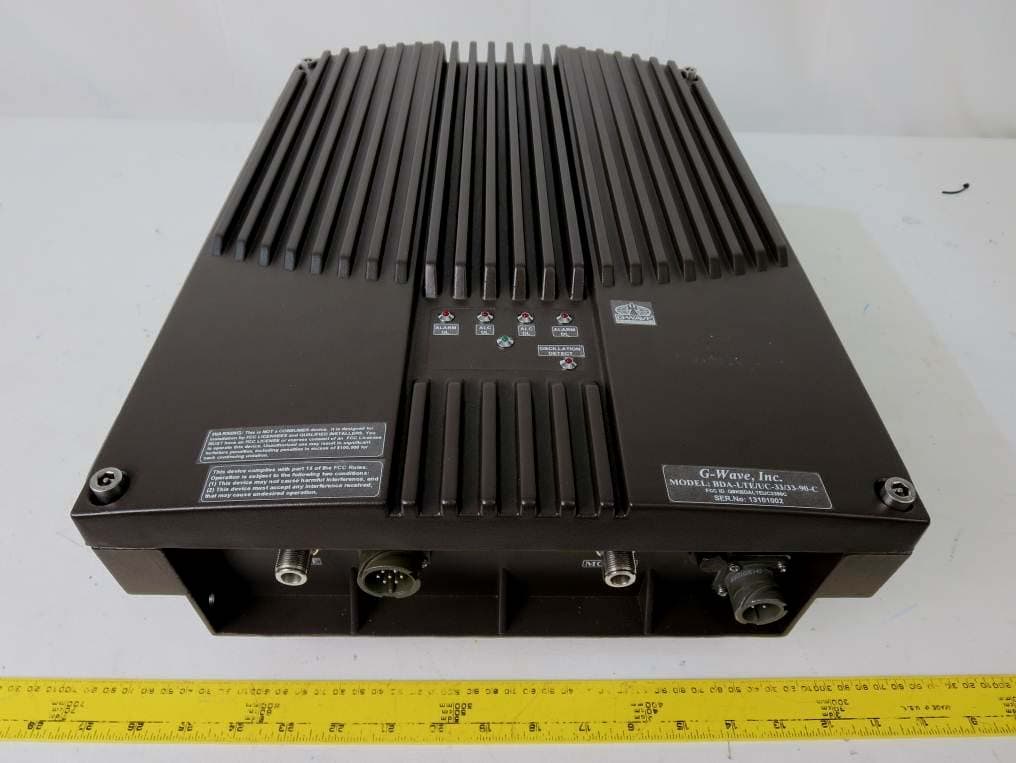
Click to zoom
Application Details
- Equipment Class
- B2I - Part 20 Industrial Booster (CMRS)
- Date of Grant
- Jan 13, 2014
- Application Purpose
- Original Equipment
- Date of Application
- Jan 13, 2014
- Equipment Note
- Upper C LTE Bi Directional Amplifier
- Frequency Range
- 776.00000000 - 787.00000000
- Company
- G-Way Solutions, LLC
- Country
- United States
Documents & Files
Document Text
Text extracted from the exhibit documents filed with the FCC. Open a document above to read the original.
Users Manual
Installation and Operating Manual LTE ‐ Upper C Band, Bi‐Directional Amplifier BDA‐LTE/UC‐33/33‐90‐C Page | 2 TABLE OF CONTENTS PARAGRAPH PAGE NO OVERVIEW 3 BLOCK DIAGRAM DESCRIPTION 3 BLOCK DIAGRAM DRAWING (Figure 1) 4 ELECTRICAL SPECIFICATIONS 5 MECHANICAL SPECIFICATIONS 6 ENVIRONMENTAL CONDITIONS 6 RF EXPOSURE WARNING 6 CONNECTIONS 7 MECHANICAL OUTLINE DRAWING (Figure 2 & 2a) 8 INSTALLATION 9 OPERATION 10 FRONT PANEL (Figure 3) BACK PANEL (Figure 3a) 11 11 DIAGNOSTICS GUIDE 12 Page | 3 OVERVIEW: The BDA-LTE/UC-33/33-90-C assembly enhances the coverage area of radio communications in buildings and RF shielded environments. The BDA-LTE/UC-33/33-90-C has dual RF paths (Forward / Reverse) to improve coverage in two distinct frequency bands. The unit features low noise figure and wide dynamic range. It is based on a dual duplexed path configuration with sharp out of band attenuation allowing improved isolation between the receiving and transmitting paths. BLOCK DIAGRAM DESCRIPTION: Refer to Figure 1 for the following discussion. The BDA-LTE/UC-33/33-90-C Downlink path receives RF signals from the base station, amplifies the signal and transmits the signal into a Distributed Antenna System at the direction of the mobiles. The signal travels over a DAS medium that then dissipates the signal to the Mobile subscribers. The BDA-LTE/UC-33/33-90-C Uplink path receives RF signals at the Mobile side from the DAS system, then amplifies it, and transmits the amplified signal to the base station. The Uplink and Downlink occupy two distinct dedicated frequency bands, each Uplink and Downlink band is 11MHz wide. For LTE Upper C Band, the frequency allocations are as follows: Uplink: 776 - 787 MHz Downlink: 746 – 757 MHz Four diplexers isolate the paths and route each signal to the proper amplifying channel. An Automatic Level Control (ALC) allows for output power limiting. A variable step attenuator gives 0 – 30 dB of attenuation in 2 dB steps. The use of these controls is covered in the “OPERATION” section, later in this document. BLOCK DIAGRAM DRAWING: (Figure 1) Page | 4 1. Input Uplink Diplexer – has low bandpass insertion loss and high selectivity for one distinct downlink/uplink frequency band. 2. Downlink Pre-amp’s – are low noise amplifiers that drive the Downlink PA’s and offer 45dB Gain. 3. Pre-Selector Filter - Downlink 4. Downlink PA’s – are power amplifiers with an ALC circuit which offer 50dB Gain. 5. Output Downlink Diplexer - has low bandpass insertion loss and high selectivity for one distinct downlink/uplink frequency band. 6. Uplink Pre-amp’s – are low noise amplifiers that drive the Uplink LPA”s and offer 45dB Gain. 7. Pre-Selector Filter - Uplink 8. Uplink LPA’s – are power amplifiers with an ALC circuit which offer 50dB Gain. Page | 5 ELECTRICAL SPECIFICATIONS: Frequency Range : UL 776 – 787 MHz DL 746 – 757 MHz Pass band Gain @ min attenuation : 90 dB (Min.) Variable Step Attenuator Range : 0-30 dB (2-dB steps) Pass band Ripple : ±2.0 dB (Typ.) . Noise Figure (Uplink) : 5.0 dB (Typ.) @+25°C at max gain 3rd Order Intercept point Downlink : +53 dBm (Typ.) Uplink : +53 dBm (Typ.) Output Power (Composite)* Downlink : +33 dBm (Typ.) Uplink : +33 dBm (Typ.) Isolation between Up/Down Link : 100 dB (Min.) Input/ Output Impedance : 50 Ohms *SFDR : 120 dB/Hz 2/3 VSWR (Input/Output) : <1.5: 1 Power Supply : 110VAC/1.1 Amps : 220VAC/0.55 Amps : 50 to 60 Hz Page | 6 MECHANICAL SPECIFICATIONS: Size : 18.1 x 14.0 x 6.7 inch : (459.74 x 355.60 x 170.18 mm) RF Connectors : N-Type Female Weight : 35.0 Lbs. (16 kg.) approx. ENVIRONMENTAL CONDITIONS: The unit is designed for indoor applications: Operating temperature: - 20°C to + 50°C Storage temperature: - 50°C to + 90°C FCC NOTE: The Federal Communications Commission (FCC) has tested this product and found it to comply with their RF Exposure Requirements, pursuant to FCC Part 27. RF EXPOSURE WARNING: In order to comply with the FCC RF exposure requirements, the BDA-LTE/UC-33/33-90-C antenna installation must comply with the following: The outdoor antenna (Yagi type or similar directional antenna if off air donor signal used) must be installed so as to provide a minimum separation distance of 0.3 meters (60 cm) between the antenna and persons within the area. (This assumes a typical antenna with gain of [10.1 dBi, VSWR ≤ 1.5:1, Zo= 50 ohms, and a cable attenuation between 1-10 dB). The indoor antenna (Omni directional or leaky cable) must be installed so as to provide a minimum separation distance of at least 8 inches (20 cm) between the indoor antenna connected to the RF booster and the human user’s body within the area. (This assumes a typical wide-beam type antenna with gain of 0-2 dBi, VSWR ≤ 2:1, Zo= 50 ohms, and a cable attenuation of between 1-10 dB). CONNECTIONS: The BDA AC power is accepted through a circular 3-wire female plug with phase, neutral and ground leads. The AC power is wired to a high efficiency DC switching power supply which is CE and UL approved. The power supply runs the amplifiers and the LED indicators. The metal enclosure of the BDA is connected to ground. A 7-pin circular connector provides failure and Oscillation Detect alarms output dry contacts, Normally Open and Normally Closed (see diagrams on page 8). The RF connections are made via two type “N” female connectors. The RF connector labeled “BASE” must be connected to the antenna pointing towards the base station. The RF connection labeled “MOBILE” must be connected to the antenna / passive DAS facing the area to be covered by the BDA. The RF connections must be made through cables with characteristic impedance of 50 ohms. The isolation between the base station antenna and the mobile antenna should be at least 12 dB higher than the BDA gain. Isolation less than this value can cause gain ripple across the band. Isolation equal to or less than the BDA gain will give rise to oscillations which will saturate the amplifiers and possibly cause damage to the BDA. This BDA i…
Text truncated - open the document above for the full version.
Cover Letter(s)
QA-FR-170-A FCC Authorization 10/22/2013 FEDERAL COMMUNICATIONS COMMISSIONS Authorization and Evaluation Division 7435 Oakland Mills Road Columbia, MD 21046 Subject: Agent Authorization To whom it may concern: We G-Way Microwave, the undersigned, Hereby authorizes Bay Area Compliance Laboratories Corporation to act on its behalf in all matters relating to application for Equipment authorization, including the signing of all documents relating to these matters. All acts carried out by Bay Area Compliance Laboratory Corporation on our behalf shall have the same effect as our own action. We, the undersigned, hereby certify that we are not subject to a denial of federal benefits, that includes FCC benefits, pursuant to Section 5301 of the Anti-Drug Abuse Act of 1988, 21 U.S.C. 853(a). This authorization is valid until further written notice from the applicant. Sincerely Yours, ____________________________ Greg David - Technical Director 38 Leuning Street, S.Hackensack, NJ 07606 Tel: 201-343-6388
Cover Letter(s)
QA-FR-172-A FCC Confidential Authorization 2013/10/17 FEDERAL COMMUNICATIONS COMMISSIONS Authorization and Evaluation Division 7435 Oakland Mills Road Columbia, MD 21046 Subject: Confidentiality Request regarding application for certification of FCC ID: Q8KBDALTEUC3390C In accordance with Sections 0.457 and 0.459 of the Commission’s Rules, G-Way Microwave hereby requests long-term confidential treatment of information accompanying this application as outlined below: Block Diagram Schematics Operation Description As well as short-term confidential treatment of information accompanying this application as outlined below: Internal Photos User’s Manual External Photos Test Set-up Photos The above materials contain proprietary and confidential information not customarily released to the public. The public disclosure of these materials provides unjustified benefits to its competitors in the market. Sincerely, _________________________ Greg David - Technical Director 38 Leuning Street, S.Hackensack, NJ 07606 Tel: 201-343-6388
External Photos
G-Way Microwave FCC ID: Q8KBDALTEUC3390C Report Number: R13100115-27 Page 77 of 85 FCC Part 27 Test Report 13 Exhibit C – EUT Photographs 13.1 EUT - Top View 13.2 EUT - Bottom View G-Way Microwave FCC ID: Q8KBDALTEUC3390C Report Number: R13100115-27 Page 78 of 85 FCC Part 27 Test Report 13.3 EUT - Ports View 13.4 EUT - Side View
ID Label/Location Info
FCC ID Label Industrial Booster Warning Label FCC ID Label Location
Internal Photos
G-Way Microwave FCC ID: Q8KBDALTEUC3390C Report Number: R13100115-27 Page 79 of 85 FCC Part 27 Test Report 13.5 EUT – Open-chassis View 13.6 EUT – Main PCB Board Assembly Components View G-Way Microwave FCC ID: Q8KBDALTEUC3390C Report Number: R13100115-27 Page 80 of 85 FCC Part 27 Test Report 13.7 EUT – Main PCB Board Assembly Solder View 13.8 EUT – PCB Board Assembly (XML-2 E315391) Components View G-Way Microwave FCC ID: Q8KBDALTEUC3390C Report Number: R13100115-27 Page 81 of 85 FCC Part 27 Test Report 13.9 EUT – PCB Board Assembly (XML-2 E315391) Solder View 13.10 EUT – Power Supply Components View G-Way Microwave FCC ID: Q8KBDALTEUC3390C Report Number: R13100115-27 Page 82 of 85 FCC Part 27 Test Report 13.11 EUT – Power Supply Board Solder View 13.12 EUT – Front Panel L.E.D. Board View G-Way Microwave FCC ID: Q8KBDALTEUC3390C Report Number: R13100115-27 Page 83 of 85 FCC Part 27 Test Report 13.13 EUT – Band Pass Filter LTE DL View 13.14 EUT – Band Pass Filter LTE UL View G-Way Microwave FCC ID: Q8KBDALTEUC3390C Report Number: R13100115-27 Page 84 of 85 FCC Part 27 Test Report 13.15 EUT – LTE Diplexer Upper C View 13.16 EUT – DL Amplifier View G-Way Microwave FCC ID: Q8KBDALTEUC3390C Report Number: R13100115-27 Page 85 of 85 FCC Part 27 Test Report 13.17 EUT – UL Amplifier View 13.18 EUT – Gain Adjuster View --- END OF REPORT ---
RF Exposure Info
G-Way Microwave FCC ID: Q8KBDALTEUC3390C Report Number: R13100115-27 Page 72 of 85 FCC Part 27 Test Report 10 FCC §2.1091 – RF Exposure Information 10.1 Applicable Standard According to FCC §2.1091 (Mobile Devices) RF exposure is calculated. Limits for General Population/Uncontrolled Exposure Frequency Range (MHz) Electric Field Strength (V/m) Magnetic Field Strength (A/m) Power Density (mW/cm 2 ) Averaging Time (minute) Limits for General Population/Uncontrolled Exposure 0.3-1.34 614 1.63 *(100) 30 1.34-30 824/f 2.19/f *(180/f 2 ) 30 30-300 27.5 0.073 0.2 30 300-1500 / / f/1500 30 1500-100,000 / / 1.0 30 Note: f = frequency in MHz * = Plane-wave equivalent power density 10.2 MPE Prediction Predication of MPE limit at a given distance, Equation from OET Bulletin 65, Edition 97-01 S = PG/4R² Where: S = power density P = power input to antenna G = power gain of the antenna in the direction of interest relative to an isotropic radiator R = distance to the center of radiation of the antenna 700 MHz Upper C Band, Downlink: Maximum peak output power at antenna input terminal (dBm): 32.99 Maximum peak output power at antenna input terminal (mW): 1990.67 Prediction distance (cm): 20 Prediction frequency (MHz): 756 Antenna Gain, typical (dBi): 2.0 Cable Loss (dB): 1.0 Power density at predication frequency and distance (mW/cm 2 ): 0.499 MPE limit for uncontrolled exposure at predication frequency (mW/cm 2 ): 0.504 G-Way Microwave FCC ID: Q8KBDALTEUC3390C Report Number: R13100115-27 Page 73 of 85 FCC Part 27 Test Report 700 MHz Upper C Band, Uplink: Maximum peak output power at antenna input terminal (dBm): 32.99 Maximum peak output power at antenna input terminal (mW): 1990.67 Prediction distance (cm): 60 Prediction frequency (MHz): 782 Antenna Gain, typical (dBi): 10 Cable Loss (dB): 1.0 Power density at predication frequency and distance (mW/cm 2 ): 0.35 MPE limit for uncontrolled exposure at predication frequency (mW/cm 2 ): 0.521 Note: Based on the manufacturer’s declaration, the outdoor antenna (Yagi type or similar directional antenna if off air donor signal used) must be installed so as to provide a minimum separation distance of 0.3 meters (60 cm) between the antenna and persons within the area. (This assumes a typical antenna with gain of [10.1 dBi, VSWR ≤ 1.5:1, Zo= 50 ohms, and a cable attenuation between 1-10 dB). The indoor antenna (Omni directional or leaky cable) must be installed so as to provide a minimum separation distance of at least 8 inches (20 cm) between the indoor antenna connected to the RF booster and the human user’s body within the area. (This assumes a typical wide-beam type antenna with gain of 0-2 dBi, VSWR ≤ 2:1, Zo= 50 ohms, and a cable attenuation of between 1-10 dB). Results For Uplink, the highest power density level at 60 cm is below the MPE uncontrolled exposure limit. For Downlink; the highest power density level at 20 cm is below the MPE uncontrolled exposure limit.
Test Report
Note: This test report is prepared for the customer shown above and for the device described herein. It may not be duplicated or used in part without prior written consent from Bay Area Compliance Laboratories Corp. This report must not be used by the customer to claim product certification, approval, or endorsement by A2LA* or any agency of the Federal Government. * This report may contain data that are not covered by the A2LA accreditation and are marked with an asterisk “*” (Rev.3) FCC PART 27 TEST AND MEASUREMENT REPORT For G-Way Microwave 38 Leuning Street, South Hackensack, NJ 07606, USA FCC ID: Q8KBDALTEUC3390C Report Type: Original Product Type: Bi Directional Amplifier Test Engineer: Glenn Escano Report Number: R13100115-27 Report Date: 2014-01-03 Reviewed By: Ning Ma EMC Lead Prepared By: Bay Area Compliance Laboratories Corp. 1274 Anvilwood Avenue, Sunnyvale, CA 94089, USA Tel: (408) 732-9162 Fax: (408) 732 9164 G-Way Microwave FCC ID: Q8KBDALTEUC3390C Report Number: R13100115-27 Page 2 of 85 FCC Part 27 Test Report TABLE OF CONTENTS 1 GENERAL DESCRIPTION ................................................................................................................................. 5 1.1 PRODUCT DESCRIPTION FOR EQUIPMENT UNDER TEST (EUT) ........................................................................... 5 1.2 MECHANICAL DESCRIPTION .............................................................................................................................. 5 1.3 OBJECTIVE ......................................................................................................................................................... 5 1.4 RELATED SUBMITTAL(S)/GRANT(S) ................................................................................................................... 5 1.5 TEST METHODOLOGY ........................................................................................................................................ 5 1.6 MEASUREMENT UNCERTAINTY .......................................................................................................................... 6 1.7 TEST FACILITY ................................................................................................................................................... 6 2 EUT TEST CONFIGURATION ........................................................................................................................... 7 2.1 JUSTIFICATION ................................................................................................................................................... 7 2.2 EUT EXERCISE SOFTWARE ................................................................................................................................ 7 2.3 EQUIPMENT MODIFICATIONS ............................................................................................................................. 7 2.4 SPECIAL EQUIPMENT ......................................................................................................................................... 7 2.5 LOCAL SUPPORT EQUIPMENT............................................................................................................................. 7 2.6 EUT INTERNAL CONFIGURATION DETAILS ........................................................................................................ 7 2.7 EXTERNAL I/O CABLING LIST AND DETAILS ..................................................................................................... 8 3 SUMMARY OF TEST RESULTS ........................................................................................................................ 9 4 FCC §2.1046, §27.50(B) & §27.50(I) – RF OUTPUT POWER ........................................................................ 10 4.1 APPLICABLE STANDARD .................................................................................................................................. 10 4.2 TEST PROCEDURE ............................................................................................................................................ 10 4.3 TEST EQUIPMENT LIST AND DETAILS .............................................................................................................. 10 4.4 TEST ENVIRONMENTAL CONDITIONS ............................................................................................................... 10 4.5 TEST RESULTS ................................................................................................................................................. 11 5 FCC §2.1049 – OCCUPIED BANDWIDTH ...................................................................................................... 13 5.1 APPLICABLE STANDARD .................................................................................................................................. 13 5.2 TEST PROCEDURE ............................................................................................................................................ 13 5.3 TEST EQUIPMENT LIST AND DETAILS .............................................................................................................. 13 5.4 TEST ENVIRONMENTAL CONDITIONS ............................................................................................................... 13 5.5 TEST RESULTS ................................................................................................................................................. 13 6 FCC §2.1053 & §27.53 - SPURIOUS RADIATED EMISSIONS ..................................................................... 27 6.1 APPLICABLE STANDARD .................................................................................................................................. 27 6.2 TEST PROCEDURE ............................................................................................................................................ 27 6.3 TEST EQU…
Text truncated - open the document above for the full version.
Test Setup Photos
G-Way Microwave FCC ID: Q8KBDALTEUC3390C Report Number: R13100115-27 Page 75 of 85 FCC Part 27 Test Report 12 Exhibit B - Test Setup Photographs 12.1 Radiated Emissions - Front View 12.2 Radiated Emissions - Rear View (Below 1 GHz) G-Way Microwave FCC ID: Q8KBDALTEUC3390C Report Number: R13100115-27 Page 76 of 85 FCC Part 27 Test Report 12.3 Radiated Emissions - Rear View (Above 1 GHz)
Contact Information
Applicant
Sharon David(Marketing Director)
Test Firm
Bay Area Compliance Laboratories Corp.Lisa Tang
Technical Specifications
| # | Rule Parts | Frequency Range | Power Output | Emission | Tolerance |
|---|---|---|---|---|---|
| 2 | 27 | 776 MHz - 787 MHz | 2 W | G7D | Amp |
Other Applications from G-Way Solutions, LLC

Q8KUHF3680AB
Jul 17, 2015Booster
Equipment Class
B9B - Part 90 Class B Industrial Booster (non-SMR)
Q8KUHF3680R
Jul 17, 2015Booster
Equipment Class
B9B - Part 90 Class B Industrial Booster (non-SMR)
Q8KUHF3680N
Jul 17, 2015Booster
Equipment Class
B9B - Part 90 Class B Industrial Booster (non-SMR)
Q8KCELLPCS2W80N
Mar 28, 2015RigBooster PRO, Dual Band Outdoor BDA
Equipment Class
B2I - Part 20 Industrial Booster (CMRS)
Q8KCELLPCS3380AB
Mar 28, 2015Dual Band Bi-Directional Amplifier
Equipment Class
B2I - Part 20 Industrial Booster (CMRS)