Q8KCELLAB1W80Bi-Directional Booster
G-Way Solutions, LLC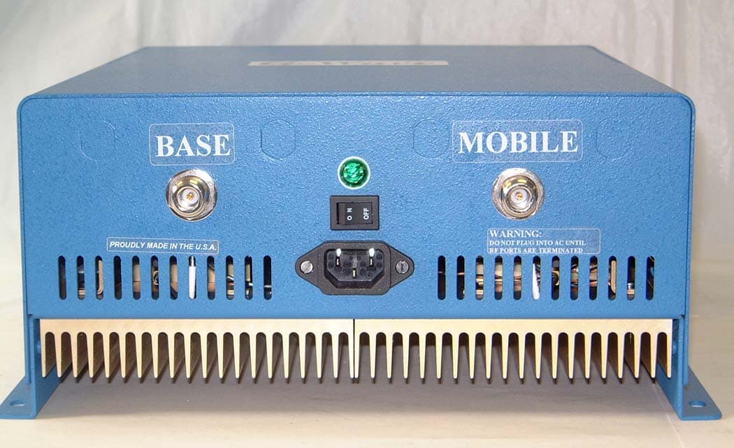
Click to zoom
Application Details
- Equipment Class
- TNB - Licensed Non-Broadcast Station Transmitter
- Date of Grant
- May 27, 2004
- Application Purpose
- Original Equipment
- Date of Application
- May 27, 2004
- Equipment Note
- Bi-Directional Booster
- Frequency Range
- 869.00000000 - 894.00000000
- Company
- G-Way Solutions, LLC
- Country
- United States
Documents & Files
Document Text
Text extracted from the exhibit documents filed with the FCC. Open a document above to read the original.
Users Manual
INSTALLATION AND OPERATING MANUAL FOR BDA-XXX-1/1W-80-B BI-DIRECTIONAL AMPLIFIER TABLE OF CONTENTS PARAGRAPH PAGE NO BDA OVERVIEW 3 BDA BLOCK DIAGRAM DESCRIPTION 3 BDA BLOCK DIAGRAM DRAWING (Figure 1) 4 ELECTRICAL SPECIFICATIONS 5 FREQUENCY RANGES (Table 1) 6 MECHANICAL SPECIFICATIONS 7 ENVIRONMENTAL CONDITIONS 7 BDA CONNECTIONS 7 MECHANICAL OUTLINE DRAWING (Figure 2 & 2a)8 RF EXPOSURE WARNING 9 BDA INSTALLATION 10 BDA OPERATION 11 MECHANICAL OUTLINE- ADJUSTMENT (Figure 3) 12 DIAGNOSTICS GUIDE 13 Page 2 BDA OVERVIEW: The BDA assembly extends the coverage area of radio communications in buildings and RF shielded environments. The unit features low noise figure and wide dynamic range. It is based on a duplexed path configuration with sharp out of band attenuation allowing improved isolation between the receiving and transmitting paths. BDA BLOCK DIAGRAM DESCRIPTION : Refer to figure 1 for the following discussion. The BDA Downlink path receives RF signals from the base station and amplifies and transmits them to the subscriber. The BDA Uplink path receives RF signals from the subscriber and amplifies and transmits them to the base station. The Uplink and Downlink occupy two distinct frequency bands. For example, the SMR frequency bands are as follows: 806-821 MHz for the Uplink and 851-866 MHz for the Downlink. Two diplexers isolate the paths and route each signal to the proper amplifying channel. A selectable Automatic Level Control (ALC) allows for output power limiting. A variable step attenuator gives 0 – 30 dB of attenuation in 2 dB steps. The use of these controls is covered in the “OPERATION” section, later in this document. Page 3 Figure 1 1. 2. 3. 6. 4. 5. BDA BLOCK DIAGRAM BDA-XXX-1/1W-80-A 1. Up-Link Diplexer - has low bandpass insertion loss and high selectivity 2. Down-Link Pre-amp - is a low noise amplifier that drives the Down-Link MPA and offers 45dB Gain 3. Down-Link MPA – is a medium power amplifier with an ALC circuit which offers 43dB Gain 4. Up-Link MPA – is a medium power amplifier with an ALC circuit which offers 43dB Gain 5. Up-Link Pre-amp - is a low noise amplifier that drives the Up-Link MPA and offers 45dB Gain 6. Down-Link Diplexer - has low bandpass insertion loss and high selectivity Page 4 ELECTRICAL SPECIFICATIONS: Frequency Range : See Table 1 Pass band Gain @ min attenuation : 80 dB minimum Variable Step Attenuator Range : 0-30 dB (2-dB steps) Pass band Ripple : ±1.5 dB (typ) Noise Figure @+25 °C at max gain : 5.0 dB max 3rd Order Intercept point Uplink : +45 dBm (typ) Downlink : +45 dBm (typ) *Output Power @ 1dB Compression Uplink : +32 dBm (typ) Downlink : +32 dBm (typ) *ALC Factory Set Point Uplink : +25 dBm Downlink : +25 dBm Isolation between Up/Down Link : 100 dB min Input/ Output Impedance : 50 Ohms VSWR (Input/Output) : 1.5: 1 max Pass band Gain @ min attenuation : 80 dB minimum Power Supply : 110VAC/0.80Amp : 240VAC/0.40 Amp : 50 to 60 Hz *The Manufacturer's rated output power of this equipment is for single carrier operation. For situations when multiple carrier signals are present, the rating would have to be reduced by 3.5 dB, especially where the output signal is re-radiated and can cause interference to adjacent band users. This power reduction is to be by means of input power or gain reduction and not by an attenuator at the output of the device. Page 5 Table 1 Frequency Bands Frequency Ranges Downlink Frequency Ranges Uplink SMR 851-866 MHz 806-821 MHz CELL A 869-880 MHz 824-835 MHz CELL B 880-894 MHz 835-849 MHz CELL AB 869-894 MHz 824-849 MHz GSM F 935-960 MHz 890-915 MHz GSM H 947-960 MHz 902-915 MHz GSM L 935-947 MHz 890-902 MHZ NPS PAC 866-869 MHz 821-824 MHz 2PG 929-942 MHz 898-904 MHz 2PGN 929-942 MHz 900-903 MHz PS8 851-869 MHz 806-824 MHz PS9 935-941 MHz 896-902 MHz Page 6 MECHANICAL SPECIFICATIONS : Size : 13.5 x 12.5 x 5.6 inch : (343 x 317.5 x 142.3 mm) RF Connectors : N-type Female Weight : 17.8 Lbs. (8.1kg.) approx. ENVIRONMENTAL CONDITIONS: The unit is designed for indoor applications: Operating temperature: - 20°C to + 50°C Storage temperature: - 50°C to + 90°C BDA CONNECTIONS The BDA AC power is accepted through a standard 3-wire male plug (IEC-320) with phase, neutral and ground leads. The AC power is wired to a high efficiency DC switching power supply which is CE and UL approved. The power supply runs the amplifiers and the Power On lamp. The metal enclosure of the BDA is connected to ground. A 9-pin D-Sub connector provides failure alarm output contacts (see diagram next page) as well as an optional 12 VDC (250mA) auxiliary output. The RF connections are made via two type “N” female connectors. The RF connector labeled “BASE” must be connected to the antenna pointing towards the base station. The RF connection labeled “MOBILE” must be connected to the antenna facing the area to be covered by the BDA. The RF connections must be made through cables with characteristic impedance of 50 ohms. The isolation between the base station antenna and the mobile antenna should be at least 12 dB higher than the BDA gain. Isolation less than this value can cause gain ripple across the band. Isolation equal to or less than the BDA gain will give rise to oscillations which will saturate the amplifiers and possibly cause damage to the BDA. Page 7 . COM. N.O. Figure 2 IN BUILDING REPEATER BDA Mechanical Outline Figure 2a (Relay Shown in Non -Alarm Condition) The alarm monitors current of both uplink and downlink amplifiers. An alarm condition N.C. will occur if either uplink or downlink amplifiers are over or under its current tolerance. Page 8 Optional Alarm Conditions RF EXPOSURE WARNING In order to satisfy the FCC RF exposure requirements, the BDA/antenna installation must comply with the following: The outdoor antenna (Yagi type or similar directional antenna) must be installed so as to provide a minimum separation distance of 0.3 meters (30 cm) between the antenna and persons within the area. (This assumes a typical antenna with gain…
Text truncated - open the document above for the full version.
Cover Letter(s)
G-Wave Incorporated 15 Ron’s Edge Road Springfield, NJ 07081 Tel 201-343-3140 Fax 201-343-6390 E-mail [email protected] Website: www.gwaverf.com April 21, 2004 Federal Communications Commission Office of Engineering and Technology 7435 Oakland Mills Rd. Columbia, MD 21046 Subject: Request for Confidentiality Dear Sir or Madam: G-Wave Incorporated respectfully requests that the schematic diagrams, block diagram, and circuit descriptions submitted with the application for certification under FCC ID: Q8KCELLAB1W80 be withheld from public disclosure. This request is made under the provisions of Section 0.457 (d) of the Commission’s rules and Section 0.552 (b) (4) of the Freedom of Information Act. This product has been developed at considerable expense, and disclosure of this information would place G- Wave Incorporated at a competitive disadvantage. Thank you for your attention to this matter. Sincerely yours, G-Wave Incorporated Greg David Sr. Technical Consultant 15 Ron's Edge Road Springfield, NJ 07081 Tel: (201) 343-3140 Fax: (201) 343-6390 www.gwaverf.com
Cover Letter(s)
G-Wave Incorporated 15 Ron’s Edge Road Springfield, NJ 07081 Tel 201-343-3140 Fax 201-343-6390 E-mail [email protected] Website: www.gwaverf.com DATE: 5/26/04 Curtis-Straus LLC 527 Great Road Littleton, MA 01460 Acknowledgement of FCC Part 90.219 / 22.383 In signing this document I acknowledge that G-Wave Inc. was informed that FCC ID: Q8KCELLAB1W80 Model BDA-CELLAB-1/1W-80-A booster must meet all criteria stated in Sections 90.219 / 22.383 for related booster in-building operations . Dated this 26 th Day of May 20 04 By: Greg David Signature Printed Title: Sr. Technical Consultant Telephone: 201-343-3140 Applicant: G-Wave, Inc. 15 Ron's Edge Road Springfield, NJ 07081 Tel: (201) 343-3140 Fax: (201) 343-6390 www.gwaverf.com
Cover Letter(s)
Response to TCB Findings 1. Please supply filter frequency response plots to demonstrate rejection of out-of band signals. Plots supplied. 2. Please supply an exhibit or correspondence showing that the applicant has been informed about 22.383. Correspondence supplied.
RF Exposure Info
Maximum Permissible Exposure (MPE) Compliance BDA-CELLAB-1/1W-80 FCC ID Q8KCELLAB1W80 At the maximum operating frequency of 894MHz (Downlink) and 849MHz (Uplink) the MPE limit for the General Population/Uncontrolled Exposure is as follows: Downlink = 0.6mW/cm2 (f/1500mW/cm2) and Uplink = 0.57mW/cm2 (f/1500mW/cm2). The analysis is provided below. Power Density (S) = EIRP/(4πR²), Therefore, R≥√EIRP/S x 4π From the above calculations, with: Downlink Maximum Antenna Gain = 2dBi Uplink Maximum Antenna Gain = 11dBi Downlink Maximum output power = 25dBm Uplink Maximum output power = 25dBm S = 0.6 mW/cm2 S = 0.57 mW/cm2 EIRP = 27dBm or 500mW (worst case) EIRP = 36dBm or 4.0W (worst case) Therefore, R= 8.14cm (Downlink) R= 23.6cm (Uplink) These are the minimum safe distances for the general population for each antenna.
Test Report
Master: Generic FCC Date: October 16, 2001 Test Report: 4W08125 Applicant: G-Wave Inc. 15 Ron’s Edge Road Springfield, NJ 07081 Equipment Under Test: BDA-CELLAB-1/1W-80-A, Bi-Directional Amplifier (EUT) FCC ID: Q8KCELLAB1W80 In Accordance With: FCC Part 22, Subpart H Tested By: Nemko Canada Inc. 303 River Road, R.R. 5 Ottawa, Ontario K1V 1H2 Authorized By: Kevin Carr, EMC/EMI/Wireless Specialist Date: 18 May 2004 Total Number of Pages: 32 Nemko Canada Inc. PROJECT NO.: 4W08125 FCC PART 22, SUBPART H EQUIPMENT: BDA-CELLAB-1/1W-80-A, Bi-Directional Amplifier Page 2 of 32 Table of Contents Section 1. Summary of Test Results ...................................................................................... 3 Section 2. General Equipment Specification......................................................................... 5 Section 3. RF Power Output ................................................................................................... 7 Section 4. Occupied Bandwidth ............................................................................................. 8 Section 5. Spurious Emissions at Antenna Terminals ....................................................... 15 Section 6. Field Strength of Spurious Emissions ................................................................ 26 Section 7. Block Diagrams ..................................................................................................... 30 Section 8. Test Equipment List ............................................................................................. 32 Nemko Canada Inc. PROJECT NO.: 4W08125 FCC PART 22, SUBPART H EQUIPMENT: BDA-CELLAB-1/1W-80-A, Bi-Directional Amplifier Page 3 of 32 Section 1. Summary of Test Results General All measurements are traceable to national standards. These tests were conducted on a sample of the equipment for the purpose of demonstrating compliance with FCC Part 22, Subpart H. THIS TEST REPORT RELATES ONLY TO THE ITEM(S) TESTED. TESTED BY: ______________________________ DATE: 17 May 2004 Daxesh Thakker, Wireless Test Engineer Nemko Canada Inc. authorizes the above named company to reproduce this report provided it is reproduced in its entirety and for use by the company’s employees only. Any use which a third party makes of this report, or any reliance on or decisions to be made based on it, are the responsibility of such third parties. Nemko Canada Inc. accepts no responsibility for damages, if any, suffered by any third party as a result of decisions made or actions based on this report. This report applies only to the items tested. Nemko Canada Inc. PROJECT NO.: 4W08125 FCC PART 22, SUBPART H EQUIPMENT: BDA-CELLAB-1/1W-80-A, Bi-Directional Amplifier Page 4 of 32 Summary Of Test Data Name Of Test Para. No. Result RF Power Output 2.1046 Complied Audio Frequency Response 2.1047 NA(1) Audio Low-Pass Filter Response 2.1047 NA(1) Modulation Limiting 2.1047 NA (1) Occupied Bandwidth 2.1049 Complied Spurious Emissions at Antenna Terminals 2.1051 Complied Field Strength of Spurious Emissions 2.1053 Complied Frequency Stability 2.1055 NA (2) Transient Frequency Behavior —— NA (3) N/A’s: 1– The EUT contains no audio circuitry 2 – The EUT contains no Band translator circuitry 3 - The EUT is not a PTT device Indoor Temperature: 23.4°C Humidity: 41 % Outdoor Temperature: 21°C Humidity: 46 % . Nemko Canada Inc. PROJECT NO.: 4W08125 FCC PART 22, SUBPART H EQUIPMENT: BDA-CELLAB-1/1W-80-A, Bi-Directional Amplifier Page 5 of 32 Section 2. General Equipment Specification Manufacturer: G-Wave Inc. Model No.: BDA-CELLAB-1/1W-80-A Serial No.: 04041115 Date Received In Laboratory: May 5, 2004 Nemko Identification No.: 1 Supply Voltage: 120VAC, 60Hz Frequency Range: Uplink: 824 – 849 MHz Downlink: 869 – 894 MHz RF Output Power (Rated) Uplink: 25.0 dBm, 0.316 watts, Total Comp. Power Downlink: 25.0 dBm, 0.316 watts, Total Comp. Power RF Output Power (measured) Uplink: TDMA 24.7 dBm, 0.295W CDMA 24.7 dBm, 0.295W AMPS 24.6 dBm, 0.288W Downlink: TDMA 24.0 dBm, 0.251W CDMA 24.1 dBm, 0.257W AMPS 24.1 dBm, 0.257W Emission Designator: DXW, F9W, F8W Nemko Canada Inc. PROJECT NO.: 4W08125 FCC PART 22, SUBPART H EQUIPMENT: BDA-CELLAB-1/1W-80-A, Bi-Directional Amplifier Page 6 of 32 Block Diagram BASEMOBILE EUT-BDA 120 V, 60 Hz A/C Mains POWER ON OFF Nemko Canada Inc. PROJECT NO.: 4W08125 FCC PART 22, SUBPART H EQUIPMENT: BDA-CELLAB-1/1W-80-A, Bi-Directional Amplifier Page 7 of 32 Section 3. RF Power Output Para. No.: 2.1046 Test Performed By: Daxesh Thakker Date of Test: May 14, 2004 Minimum Standard: 22.913(a) Test Results: Complied Measurement Data: See Attached Graphs. The maximum RF output power is within ± 1dB of the manufacturer’s rating. The RF output power is de-rated according to the number of channels via AGC and is equal to P max –10LogN. P max = Maximum RF Output Power N = Number Of Channels UL DL (dBm) (dBm) TDMA 24.7 24 CDMA 24.7 24.1 AMPS 24.6 24.1 Nemko Canada Inc. PROJECT NO.: 4W08125 FCC PART 22, SUBPART H EQUIPMENT: BDA-CELLAB-1/1W-80-A, Bi-Directional Amplifier Page 8 of 32 Section 4. Occupied Bandwidth Para. No.: 2.1049 Test Performed By: Daxesh Thakker Date of Test: May 14, 2004 Minimum Standard: 22.917, Input vs Output Test Results: Complied Measurement Data: See Attached Graphs The occupied bandwidth was measured by comparison of input to the output signal. This was done in order to determine if there was any degradation to the output signal due to the amplification through the repeater. Nemko Canada Inc. PROJECT NO.: 4W08125 FCC PART 22, SUBPART H EQUIPMENT: BDA-CELLAB-1/1W-80-A, Bi-Directional Amplifier Page 9 of 32 UL TDMA Nemko Canada Inc. PROJECT NO.: 4W08125 FCC PART 22, SUBPART H EQUIPMENT: BDA-CELLAB-1/1W-80-A, Bi-Directional Amplifier Page 10 of 32 CDMA Nemko Canada Inc. PROJECT NO.: 4W08125 FCC PART 22, SUBPART H EQUIPMENT: BDA-CELLAB-1/1W-80-A, Bi-Directional Amplifier Page 11 of 32 AMPS Nemko Canada Inc. PROJECT NO.: 4W08125 FCC PART 22, SUBPART H EQUIPMENT: B…
Text truncated - open the document above for the full version.
Test Setup Photos
Nemko Canada Inc. PROJECT NO.: 4W08125 FCC PART 22, SUBPART H EQUIPMENT: BDA-CELLAB-1/1W-80-A, Bi-Directional Amplifier Page 28 of 32 Radiated Disturbance Detailed Setup Photos: Rear Nemko Canada Inc. PROJECT NO.: 4W08125 FCC PART 22, SUBPART H EQUIPMENT: BDA-CELLAB-1/1W-80-A, Bi-Directional Amplifier Page 29 of 32 Front
Contact Information
Applicant
Sharon David(Marketing Director)
Test Firm
Nemko Canada Inc. (Ottawa)Charles Neal
Technical Specifications
| # | Rule Parts | Frequency Range | Power Output | Emission | Tolerance |
|---|---|---|---|---|---|
| 6 | 22H | 869 MHz - 894 MHz | 316.00 mW | F9W | Amp |
Other Applications from G-Way Solutions, LLC

Q8KUHF3680AB
Jul 17, 2015Booster
Equipment Class
B9B - Part 90 Class B Industrial Booster (non-SMR)
Q8KUHF3680R
Jul 17, 2015Booster
Equipment Class
B9B - Part 90 Class B Industrial Booster (non-SMR)
Q8KUHF3680N
Jul 17, 2015Booster
Equipment Class
B9B - Part 90 Class B Industrial Booster (non-SMR)
Q8KCELLPCS2W80N
Mar 28, 2015RigBooster PRO, Dual Band Outdoor BDA
Equipment Class
B2I - Part 20 Industrial Booster (CMRS)
Q8KCELLPCS3380AB
Mar 28, 2015Dual Band Bi-Directional Amplifier
Equipment Class
B2I - Part 20 Industrial Booster (CMRS)