Q8KPCS2W70ABi-Directional Booster
G-Way Solutions, LLC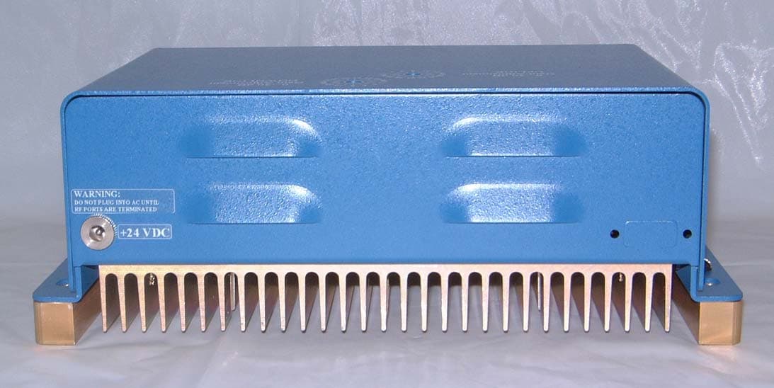
Click to zoom
Application Details
- Equipment Class
- PCB - PCS Licensed Transmitter
- Date of Grant
- Mar 25, 2004
- Application Purpose
- Original Equipment
- Date of Application
- Mar 25, 2004
- Equipment Note
- Bi-Directional Booster
- Frequency Range
- 1930.00000000 - 1990.00000000
- Company
- G-Way Solutions, LLC
- Country
- United States
Documents & Files
Document Text
Text extracted from the exhibit documents filed with the FCC. Open a document above to read the original.
Cover Letter(s)
-----Original Message----- From: Steven Dayhoff [mailto:[email protected]] Sent: Wednesday, March 24, 2004 8:04 AM To: Ruby Dulmage Subject: RE: Question on new AMP/BOOSTER/REPEATER policy - Separate FCC ID's Hi Ruby: Since the units have the capability to amplify all 6 blocks, they are of similar design, and may be certified under one FCCID number. Regards, Steve Dayhoff FCC -----Original Message----- From: Ruby Dulmage [mailto:[email protected]] Sent: Tuesday, March 23, 2004 3:53 PM To: Steven Dayhoff; Barry Quinlan - Curtis-Straus (E-mail) Cc: Yunus Faziloglu - Curtis-Straus (E-mail) Subject: RE: Question on new AMP/BOOSTER/REPEATER policy - Separate FCC ID's Importance: High Hi Steve: Further to our telephone conversation, this is the description of the device in question. This device has 6 blocks (A,B,C,D,E & F). These units use identical electronics except for the diplexer which allows for operation across the 6 bands. The diplexer is a passive component. Please refer to the block diagram on page 4 of the manual (attached). All of the units use idential uplink/downlink preamplifier, attenuator, gain block & medium power amplifier. Please confirm as per our conversation, that this device can be approved with only one FCC ID. Thanks you in advance for your time. Ruby Dulmage Certification Administrator Nemko Canada Inc. Tel: 613-737-9680 ext 232 Toll Free: 1-800-563-6336 ext 232 Fax: 613-737-9691 email: [email protected]
Cover Letter(s)
Hi Yunus: Please reference email below received from the FCC. Thanks, Ruby Ruby Dulmage Certification Administrator Nemko Canada Inc. Tel: 613-737-9680 ext 232 Toll Free: 1-800-563-6336 ext 232 Fax: 613-737-9691 email: [email protected] I am about to test and submit 6 PCS cellular band amplifiers. They are contiguous bands of: Uplink A 1850-1865MHZ Downlink A 1930-1945MHz B 1870-1885MHz B 1950-1965MHz C 1895-1910MHz C 1975-1990MHz D 1865-1870MHz D 1945-1950MHz E 1885-1890MHz E 1965-1970MHz F 1890-1895MHz F 1970-1975MHz They are all identical except for different diplexers which allow for the different Freq. bands. My question is, can I submit one report for all (i.e.. one FCC ID), and show test data compliance using the bottom, middle and top bands: ***************************************************************************************************************** ************************************* Hi Glen: Yes, they may all be certified under one FCCID application. As you stated, the low, middle, and high bands must be tested. Regards, Steven Dayhoff FCC -----Original Message----- From: Curtis-Straus Certification Dept. [mailto:[email protected]] Sent: Thursday, March 25, 2004 4:23 PM To: Ruby Dulmage Subject: CS01176 G-Wave FCC ID: Q8KPCS2W70A TCB Findings 2 Hello Ruby, We'll need test data for the additional D, E and F blocks. Test report only addresses A, B and C blocks. Best Regards, Yunus Faziloglu Reviewing Engineer Curtis-Straus TCB
Cover Letter(s)
G-Wave Incorporated 15 Ron’s Edge Road Springfield, NJ 07081 Tel 201-343-3140 Fax 201-343-6390 E-mail [email protected] Website: www.gwaverf.com February 16, 2004 G-Wave Incorporated respectfully states that all models for certification under FCC ID Q8KPCS2W70A and Industry Canada ID 4901A-PCS2W70A are identical except for different diplexers which allow for the distinct frequency band blocks. Sincerely yours, G-Wave Incorporated Greg David Sr. Technical Consultant 15 Ron's Edge Road Springfield, NJ 07081 Tel: (201) 343-3140 Fax: (201) 343-6390 www.gwaverf.com
Cover Letter(s)
Response to TCB Findings 1. In the labels ":" is missing after the FCC ID, instead a "." is used. Please provide corrected label samples and also specify the label material. Corrected and supplied. Label material is Brother P-TouchTX laminated label. 2. Please provide operational descriptions for all blocks. Technical descriptions for all 6 blocks (A,B,C,D,E,F) supplied. 3. On Page 19 of the report GSM plot is included under IS-95. The plot on page 21 also belongs to GSM. Please provide the plot for IS-95 for the B-Block UL configuration. Uploaded plots in response to questions 3 & 4. 4. On page 22 of the report; for C-Block IS-95 UL plot, the two-tone intermodulation test has been performed at mid-band. To be consistent with the plots on the following two pages (23 and 24) please submit two-tone plot for the higher end of the C-Block UL band. Uploaded plots in response to questions 3 & 4. 5. Please describe how the rejection of out-of band signals are ensured. Either test data or filter frequency response plots are required. Frequency response plots supplied. 6. Please describe the purpose of the external bias-tee shown on Page 3 of the manual in more details. Has this configuration been tested for compliance. Please clarify. The Bias Tee is an optional accessory for use with only .1/.1 watt models as a line amplifier not a repeater. This option is not applicable to the tested systems for compliance. I added a note in the manual to clarify this. 7. Please specify to what levels can the output power be reduced from the values listed on Form 731 by using the step attenuator. What will be the RF power output at the antenna terminals at maximum attenuation? The levels can be reduced by 30 dB using the step attenuator. At maximum attenuation for all blocks of the Uplink, output power is reduced from .063 to .000063 watts and for all blocks of the Downlink, output power is reduced from .501 to .000501 watts. 8. Please include exhibit or correspondence showing applicant was informed that boosters must meet all criteria stated in 22.383 (applies to 24E as well) for related booster in-building operations. Applicant has been informed.
RF Exposure Info
Maximum Permissible Exposure (MPE) Compliance BDA-PCS/A-.5/2W-70-A FCC ID Q8KPCS2W70A At the maximum operating frequency of 1945MHz (Downlink) and 1865MHz (Uplink) the MPE limit for the General Population/Uncontrolled Exposure is as follows: Downlink = 1.0mW/cm2 and Uplink = 1.0mW/cm2. The analysis is provided below. Power Density (S) = EIRP/(4πR²), Therefore, R≥√EIRP/S x 4π From the above calculations, with: Downlink Maximum Antenna Gain = 2dBi Uplink Maximum Antenna Gain = 11dBi Downlink Maximum output power = 27dBm Uplink Maximum output power = 18dBm S = 1.0 mW/cm2 S = 1.0 mW/cm2 EIRP = 29dBm or .794W (worst case) EIRP = 29dBm or .794W (worst case) Therefore, R= 7.95cm (Downlink) R= 7.95cm (Uplink) These are the minimum safe distances for the general population for each antenna. Maximum Permissible Exposure (MPE) Compliance BDA-PCS/B-.5/2W-70-A FCC ID Q8KPCS2W70A At the maximum operating frequency of 1965MHz (Downlink) and 1885MHz (Uplink) the MPE limit for the General Population/Uncontrolled Exposure is as follows: Downlink = 1.0mW/cm2 and Uplink = 1.0mW/cm2. The analysis is provided below. Power Density (S) = EIRP/(4πR²), Therefore, R≥√EIRP/S x 4π From the above calculations, with: Downlink Maximum Antenna Gain = 2dBi Uplink Maximum Antenna Gain = 11dBi Downlink Maximum output power = 29dBm Uplink Maximum output power = 21dBm S = 1.0 mW/cm2 S = 1.0 mW/cm2 EIRP = 29dBm or .794W (worst case) EIRP = 29dBm or .794W (worst case) Therefore, R= 7.95cm (Downlink) R= 7.95cm (Uplink) These are the minimum safe distances for the general population for each antenna. Maximum Permissible Exposure (MPE) Compliance BDA-PCS/C-.5/2W-70-A FCC ID Q8KPCS2W70A At the maximum operating frequency of 1990MHz (Downlink) and 1910MHz (Uplink) the MPE limit for the General Population/Uncontrolled Exposure is as follows: Downlink = 1.0mW/cm2 and Uplink = 1.0mW/cm2. The analysis is provided below. Power Density (S) = EIRP/(4πR²), Therefore, R≥√EIRP/S x 4π From the above calculations, with: Downlink Maximum Antenna Gain = 2dBi Uplink Maximum Antenna Gain = 11dBi Downlink Maximum output power = 29dBm Uplink Maximum output power = 21dBm S = 1.0 mW/cm2 S = 1.0 mW/cm2 EIRP = 29dBm or .794W (worst case) EIRP = 29dBm or .794W (worst case) Therefore, R= 7.95cm (Downlink) R= 7.95cm (Uplink) These are the minimum safe distances for the general population for each antenna. Maximum Permissible Exposure (MPE) Compliance BDA-PCS/D-.5/2W-70-A FCC ID Q8KPCS2W70A At the maximum operating frequency of 1950MHz (Downlink) and 1870MHz (Uplink) the MPE limit for the General Population/Uncontrolled Exposure is as follows: Downlink = 1.0mW/cm2 and Uplink = 1.0mW/cm2. The analysis is provided below. Power Density (S) = EIRP/(4πR²), Therefore, R≥√EIRP/S x 4π From the above calculations, with: Downlink Maximum Antenna Gain = 2dBi Uplink Maximum Antenna Gain = 11dBi Downlink Maximum output power = 27dBm Uplink Maximum output power = 18dBm S = 1.0 mW/cm2 S = 1.0 mW/cm2 EIRP = 29dBm or 0.794W (worst case) EIRP = 29dBm or 0.794W (worst case) Therefore, R= 7.95cm (Downlink) R= 7.95cm (Uplink) These are the minimum safe distances for the general population for each antenna. Maximum Permissible Exposure (MPE) Compliance BDA-PCS/E-.5/2W-70-A FCC ID Q8KPCS2W70A At the maximum operating frequency of 1970MHz (Downlink) and 1890MHz (Uplink) the MPE limit for the General Population/Uncontrolled Exposure is as follows: Downlink = 1.0mW/cm2 and Uplink = 1.0mW/cm2. The analysis is provided below. Power Density (S) = EIRP/(4πR²), Therefore, R≥√EIRP/S x 4π From the above calculations, with: Downlink Maximum Antenna Gain = 2dBi Uplink Maximum Antenna Gain = 11dBi Downlink Maximum output power = 27dBm Uplink Maximum output power = 18dBm S = 1.0 mW/cm2 S = 1.0 mW/cm2 EIRP = 29dBm or 0.794W (worst case) EIRP = 29dBm or 0.794W (worst case) Therefore, R= 7.95cm (Downlink) R= 7.95cm (Uplink) These are the minimum safe distances for the general population for each antenna. Maximum Permissible Exposure (MPE) Compliance BDA-PCS/F-.5/2W-70-A FCC ID Q8KPCS2W70A At the maximum operating frequency of 1975MHz (Downlink) and 1895MHz (Uplink) the MPE limit for the General Population/Uncontrolled Exposure is as follows: Downlink = 1.0mW/cm2 and Uplink = 1.0mW/cm2. The analysis is provided below. Power Density (S) = EIRP/(4πR²), Therefore, R≥√EIRP/S x 4π From the above calculations, with: Downlink Maximum Antenna Gain = 2dBi Uplink Maximum Antenna Gain = 11dBi Downlink Maximum output power = 27dBm Uplink Maximum output power = 18dBm S = 1.0 mW/cm2 S = 1.0 mW/cm2 EIRP = 29dBm or 0.794W (worst case) EIRP = 29dBm or 0.794W (worst case) Therefore, R= 7.95cm (Downlink) R= 7.95cm (Uplink) These are the minimum safe distances for the general population for each antenna.
RF Exposure Info
4W07892Downlink Prediction of MPE limit at a given distance Equation from page 18 of OET Bulletin 65, Edition 97-01where: S = power density P = power input to the antennaG = power gain of the antenna in the direction of interest relative to an isotropic radiatorR = distance to the center of radiation of the antenna Maximum peak output power at antenna input terminal: 27.00 (dBm) Maximum peak output power at antenna input terminal: 501.187234 (mW) Antenna gain(typical): 2 (dBi) Maximum antenna gain: 1.58489319 (numeric) Prediction distance: 20 (cm) Prediction frequency: 1910 - 1990 (MHz) MPE limit for uncontrolled exposure at prediction frequency: 1.0 (mW/cm^2) Power density at prediction frequency: 0.158027 (mW/cm^2) Maximum allowable antenna gain: 10.0126986 (dBi) Margin of Compliance: 8.01269855 (dB) 2 4 R PG S π =
RF Exposure Info
4W07892Uplink Prediction of MPE limit at a given distance Equation from page 18 of OET Bulletin 65, Edition 97-01where: S = power density P = power input to the antennaG = power gain of the antenna in the direction of interest relative to an isotropic radiatorR = distance to the center of radiation of the antenna Maximum peak output power at antenna input terminal: 18.00 (dBm) Maximum peak output power at antenna input terminal: 63.0957344 (mW) Antenna gain(typical): 11 (dBi) Maximum antenna gain: 12.5892541 (numeric) Prediction distance: 20 (cm) Prediction frequency: 1850 - 1910 (MHz) MPE limit for uncontrolled exposure at prediction frequency: 1.0 (mW/cm^2) Power density at prediction frequency: 0.158027 (mW/cm^2) Maximum allowable antenna gain: 19.0126986 (dBi) Margin of Compliance: 8.01269855 (dB) 2 4 R PG S π =
Test Report
Q3. Q. 4.
Test Report
Master: FCC-PR24-E Date: February 13, 2002 Test Report: 4W07892 Applicant: G-Wave Inc. 15 Ron’s Edge Road Springfield, NJ 07081 Equipment Under Test: BDA-PCS/A-.5/2W-70-A, BDA-PCS/B-.5/2W-70-A & (EUT) BDA-PCS/C-.5/2W-70-A FCC ID: Q8KPCS2W70A In Accordance With: FCC Part 24, Subpart E Tested By: Nemko Canada Inc. 303 River Road, R.R. 5 Ottawa, Ontario K1V 1H2 Authorized By: Glen Westwell, Wireless Specialist Date: 10 March 2004 Total Number of Pages: 40 Nemko Canada Inc. FCC PART 24, SUBPART E PROJECT NO.:4W07892 EQUIPMENT: BDA-PCS/A-.5/2W-70-A & BDA-PCS/B-.5/2W-70-A & BDA-PCS/C-.5/2W-70-A Page 2 of 40 Table of Contents Section 1. Summary of Test Results .................................................................................. 3 Section 2. General Equipment Specification..................................................................... 5 Section 3. RF Power Output ............................................................................................... 7 Section 4. Occupied Bandwidth ......................................................................................... 8 Section 5. Spurious Emissions at Antenna Terminals ................................................... 15 Section 6. Field Strength of Spurious .............................................................................. 34 Section 7. Block Diagrams ................................................................................................ 37 Section 8. Test Equipment List ........................................................................................ 40 Nemko Canada Inc. FCC PART 24, SUBPART E PROJECT NO.:4W07892 EQUIPMENT: BDA-PCS/A-.5/2W-70-A & BDA-PCS/B-.5/2W-70-A & BDA-PCS/C-.5/2W-70-A Page 3 of 40 Section 1. Summary of Test Results General All measurements are traceable to national standards. These tests were conducted on a sample of the equipment for the purpose of demonstrating compliance with FCC Part 24, Subpart E. THIS TEST REPORT RELATES ONLY TO THE ITEM(S) TESTED. THE FOLLOWING DEVIATIONS FROM, ADDITIONS TO, OR EXCLUSIONS FROM THE TEST SPECIFICATIONS HAVE BEEN MADE. NONE See “ Summary of Test Data”. TESTED BY: ______________________________ DATE: 4 March 2004 Kevin Carr, EMC/EMI/Wireless Specialist Nemko Canada Inc. authorizes the above named company to reproduce this report provided it is reproduced in its entirety and for use by the company’s employees only. Any use which a third party makes of this report, or any reliance on or decisions to be made based on it, are the responsibility of such third parties. Nemko Canada Inc. accepts no responsibility for damages, if any, suffered by any third party as a result of decisions made or actions based on this report. This report applies only to the items tested. Nemko Canada Inc. FCC PART 24, SUBPART E PROJECT NO.:4W07892 EQUIPMENT: BDA-PCS/A-.5/2W-70-A & BDA-PCS/B-.5/2W-70-A & BDA-PCS/C-.5/2W-70-A Page 4 of 40 Summary Of Test Data Name Of Test Para. No. Result RF Power Output 2.1046 Complied Occupied Bandwidth 2.1049 Complied Spurious Emissions at Antenna Terminals 2.1051 Complied Field Strength of Spurious Emissions 2.1053 Complied Frequency Stability 2.1055 N/A(1) Footnotes For N/A’s: N/A(1) – The EUT is a F1 – F1 BDA Test Conditions: Indoor Temperature: 24°C Humidity: 13% Outdoor Temperature: 3°C Humidity: 93% Nemko Canada Inc. FCC PART 24, SUBPART E PROJECT NO.:4W07892 EQUIPMENT: BDA-PCS/A-.5/2W-70-A & BDA-PCS/B-.5/2W-70-A & BDA-PCS/C-.5/2W-70-A Page 5 of 40 Section 2. General Equipment Specification Manufacturer: G-Wave Inc. Model No.: BDA-PCS/A-.5/2W-70-A BDA-PCS/B-.5/2W-70-A BDA-PCS/C-.5/2W-70-A Serial No.: 04021001 04021001 04021002 Date Received In Laboratory: 23 Feb. 2004 Nemko Identification No.: 1, 2, 4, 7 Supply Voltage: 120VAC, 60Hz Frequency Range: Uplink: 1850 – 1910MHz Downlink: 1930 – 1990MHz RF Output Power (Rated) Uplink: 18.0dBm, Total Composite Power, 2 Tones Downlink: 27.0 dBm, Total Composite Power, 2 Tones RF Output Power (measured) Uplink: 18.5dBm, Total Composite Power, 2 Tones Downlink: 27.2 dBm, Total Composite Power, 2 Tones Emission Designator: DXW, F9W, GXW Nemko Canada Inc. FCC PART 24, SUBPART E PROJECT NO.:4W07892 EQUIPMENT: BDA-PCS/A-.5/2W-70-A & BDA-PCS/B-.5/2W-70-A & BDA-PCS/C-.5/2W-70-A Page 6 of 40 Block Diagram DL I/P UL I/P EUT AC/DC Converter CINCON ELECTRONICS TR70A24 POWER SUPPLY S/N 70240-0066225 c/w CORD 120VAC, 60Hz Nemko Canada Inc. FCC PART 24, SUBPART E PROJECT NO.:4W07892 EQUIPMENT: BDA-PCS/A-.5/2W-70-A & BDA-PCS/B-.5/2W-70-A & BDA-PCS/C-.5/2W-70-A Page 7 of 40 Section 3. RF Power Output Para. No.: 2.1046 Test Performed By: Kevin Carr Date of Test: 25 Feb. 2004 Minimum Standard: Para. No.: 24.232. Test Results: Complied Measurement Data: See attached chart, The maximum RF output power is within +/- 1 dB of the manufacturer’s rating, The RF output power is de-rated according to the number of channels via AGC and is equal to Pmax –10logN. Pmax = Max. RF output power N = Number of Channels ChannelRated MeasuredDelta dBm dBm dB Low 18.0 17.9 0.1 UL Mid 18.0 17.5 0.5 High 18.0 18.5 0.5 Low 27.0 27.2 0.2 DL Mid 27.0 26.2 0.8 High 27.0 27.1 0.1 Nemko Canada Inc. FCC PART 24, SUBPART E PROJECT NO.:4W07892 EQUIPMENT: BDA-PCS/A-.5/2W-70-A & BDA-PCS/B-.5/2W-70-A & BDA-PCS/C-.5/2W-70-A Page 8 of 40 Section 4. Occupied Bandwidth Para. No.: 2.1049 Test Performed By: Kevin Carr Date of Test: 25 Feb. 2004 Minimum Standard: Para. No.: 24.238. Test Results: Complied Test Data: See attached graph(s). Nemko Canada Inc. FCC PART 24, SUBPART E PROJECT NO.:4W07892 EQUIPMENT: BDA-PCS/A-.5/2W-70-A & BDA-PCS/B-.5/2W-70-A & BDA-PCS/C-.5/2W-70-A Page 9 of 40 Uplink IS – 95 Nemko Canada Inc. FCC PART 24, SUBPART E PROJECT NO.:4W07892 EQUIPMENT: BDA-PCS/A-.5/2W-70-A & BDA-PCS/B-.5/2W-70-A & BDA-PCS/C-.5/2W-70-A Page 10 of 40 IS – 136 Nemko Canada Inc. FCC PART 24, SUBPART E PROJECT NO.:4W07892 EQUIPMENT: BDA-PCS/A-.5/2W-70-A & BDA-PCS/B-.5/2W-70-A & BDA-PCS/C-.5/2W-70-A Page 11 of 40 GSM Nemko Canada Inc.…
Text truncated - open the document above for the full version.
Contact Information
Applicant
Sharon David(Marketing Director)
Test Firm
Nemko Canada Inc.Stuart Beck
Technical Specifications
| # | Rule Parts | Frequency Range | Power Output | Emission | Tolerance |
|---|---|---|---|---|---|
| 6 | 24E | 1.93 GHz - 1.99 GHz | 501.00 mW | GXW | Amp |
Other Applications from G-Way Solutions, LLC

Q8KUHF3680AB
Jul 17, 2015Booster
Equipment Class
B9B - Part 90 Class B Industrial Booster (non-SMR)
Q8KUHF3680R
Jul 17, 2015Booster
Equipment Class
B9B - Part 90 Class B Industrial Booster (non-SMR)
Q8KUHF3680N
Jul 17, 2015Booster
Equipment Class
B9B - Part 90 Class B Industrial Booster (non-SMR)
Q8KCELLPCS2W80N
Mar 28, 2015RigBooster PRO, Dual Band Outdoor BDA
Equipment Class
B2I - Part 20 Industrial Booster (CMRS)
Q8KCELLPCS3380AB
Mar 28, 2015Dual Band Bi-Directional Amplifier
Equipment Class
B2I - Part 20 Industrial Booster (CMRS)