Q8KPS7PS82W80DUAL BAND RF BI-DIRECTIONAL AMPLIFIER
G-Way Solutions, LLC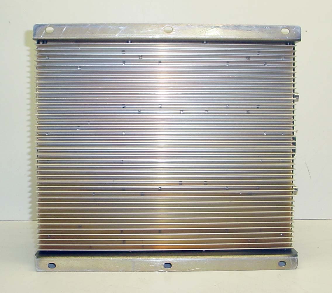
Click to zoom
Application Details
- Equipment Class
- TNB - Licensed Non-Broadcast Station Transmitter
- Date of Grant
- Jan 11, 2007
- Application Purpose
- Original Equipment
- Date of Application
- Jan 11, 2007
- Equipment Note
- DUAL BAND RF BI-DIRECTIONAL AMPLIFIER
- Frequency Range
- 851.00000000 - 869.00000000
- Company
- G-Way Solutions, LLC
- Country
- United States
Documents & Files
Document Text
Text extracted from the exhibit documents filed with the FCC. Open a document above to read the original.
Users Manual
INSTALLATION AND OPERATING MANUAL BDA-PS7/PS8-2/2W-80-A DUAL BAND BI-DIRECTIONAL AMPLIFIER TABLE OF CONTENTS PARAGRAPH PAGE NO BDA OVERVIEW 3 BDA BLOCK DIAGRAM DESCRIPTION 3 ELECTRICAL SPECIFICATIONS 4 MECHANICAL SPECIFICATIONS 5 ENVIRONMENTAL CONDITIONS 5 BDA CONNECTIONS 5 MECHANICAL OUTLINE DRAWING (Figure 1 & 1a) 6 BDA INSTALLATION 7 BDA OPERATION 8 UPLINK MECHANICAL OUTLINE- ADJUSTMENT (Figure 2) 9 DOWNLINK MECHANICAL OUTLINE- ADJUSTMENT (Figure 3) 10 RF EXPOSURE WARNING 11 DIAGNOSTICS GUIDE 11 Page 2 BDA OVERVIEW: The BDA assembly extends the coverage area of radio communications in buildings and RF shielded environments. The BDA has dual RF paths to extend coverage in two distinct frequency bands. The unit features low noise figure and wide dynamic range. It is based on a duplexed path configuration with sharp out of band attenuation allowing improved isolation between the receiving and transmitting paths. BDA DESCRIPTION : The BDA Downlink path receives RF signals from the base station and amplifies and transmits them to the subscriber. The BDA Uplink path receives RF signals from the subscriber and amplifies and transmits them to the base station. The Uplink and Downlink occupy three distinct frequency bands. The frequency bands are as follows: 794-824 MHz for the Uplink and 764-776 MHz & 851-869 MHz for the Downlink. Two triplexers isolate the paths and route each signal to the proper amplifying channel. An Automatic Level Control (ALC) allows for output power limiting. A variable step attenuator gives 0 – 30 dB of attenuation in 2 dB steps. The use of these controls is covered in the “OPERATION” section, later in this document. Page 3 ELECTRICAL SPECIFICATIONS: Frequency Range Downlink : 764-776 and 851-869 MHz Uplink : 794-824 MHz Pass band Gain @ min attenuation : 80 dB minimum Variable Step Attenuator Range : 0-30 dB (2-dB steps) Pass band Ripple : ±1.5 dB (typ) Noise Figure @+25 °C at max gain : 5.5 dB max 3rd Order Intercept point Uplink : +46 dBm (typ) Downlink : +46 dBm (typ) *Output Power @ 1dB Compression Uplink : +33 dBm (typ) Downlink : +33 dBm (typ) *ALC Factory Set Point Uplink : +26 dBm Downlink : +26 dBm Isolation between Up/Down Link : 100 dB min Input/ Output Impedance : 50 Ohms VSWR (Input/Output) : 1.5: 1 max Pass band Gain @ min attenuation : 80 dB minimum Power Supply : 110VAC/1.42Amp : 240VAC/0.71 Amp : 50 to 60 Hz *The Manufacturer's rated output power of this equipment is for single carrier operation. For situations when multiple carrier signals are present, the rating would have to be reduced by 3.5 dB, especially where the output signal is re-radiated and can cause interference to adjacent band users. This power reduction is to be by means of input power or gain reduction and not by an attenuator at the output of the device. Page 4 MECHANICAL SPECIFICATIONS : Size : 13.5 x 12.5 x 5.6 inch : (343 x 317.5 x 142.3 mm) RF Connectors : N-type Female Weight : 20.9 Lbs. (9.5kg.) approx. ENVIRONMENTAL CONDITIONS: The unit is designed for indoor applications: Operating temperature: - 20°C to + 50°C Storage temperature: - 50°C to + 90°C BDA CONNECTIONS The BDA AC power is accepted through a standard 3-wire male plug (IEC-320) with phase, neutral and ground leads. The AC power is wired to a high efficiency DC switching power supply which is CE and UL approved. The power supply runs the amplifiers and the Power On lamp. The metal enclosure of the BDA is connected to ground. A 9-pin D-Sub connector provides failure alarm output contacts (see diagram next page) as well as an optional 12 VDC (250mA) auxiliary output. The RF connections are made via two type “N” female connectors. The RF connector labeled “BASE” must be connected to the antenna pointing towards the base station. The RF connection labeled “MOBILE” must be connected to the antenna facing the area to be covered by the BDA. The RF connections must be made through cables with characteristic impedance of 50 ohms. The isolation between the base station antenna and the mobile antenna should be at least 12 dB higher than the BDA gain. Isolation less than this value can cause gain ripple across the band. Isolation equal to or less than the BDA gain will give rise to oscillations which will saturate the amplifiers and possibly cause damage to the BDA. Page 5 N.O. COM. N.C. IN BUILDING REPEATER Figure 1 BDA Mechanical Outline Figure 1a (Relay Shown in Non -Alarm Condition) The alarm monitors current of both uplink and downlink amplifiers. An alarm condition will occur if either uplink or downlink amplifiers are over or under its current tolerance. Page 6 Conditions for Optional Alarm BDA INSTALLATION DO NOT APPLY A.C. POWER TO THE BDA UNTIL CABLES ARE CONNECTED TO BOTH PORTS OF THE BDA AND THE ANTENNAS. 1. Mount the BDA on the wall with the RF connectors pointing DOWN. Using appropriate screws and anchors, attach the BDA to the wall at the four mounting holes on the side flanges. 2. Ensure that the isolation between the donor antenna and the service antenna is at least 12 dB greater than the BDA gain. (Use the higher of the Uplink and Downlink gains reported on the BDA test data sheet). 3. Connect the cable from the donor antenna to the BDA connector labeled “BASE” and the cable from the service antennas to the BDA connector labeled “MOBILE”. 4. Open the adjustment access panels on the sides of the BDA and verify that both of the attenuator’s are positioned to its maximum setting (30 dB). Close the panels. 5. Connect the AC power cord to the BDA and then to the power source. Verify that the “Power ON” lamp is illuminated. Installation of the BDA is now complete. To adjust the gain controls to suit the specific signal environment, refer to the next section of the manual. Note : For repeat installations of existing equipment, make sure the attenuation is positioned to its maximum setting (30 dB). After verification of the attenuation, follow the above steps starting with step 1. Page 7 BDA OPERATION Refer to Figure…
Text truncated - open the document above for the full version.
Cover Letter(s)
G-Wave Incorporated 15 Ron’s Edge Road Springfield, NJ 07081 Tel 201-343-3140 Fax 201-343-6390 E-mail [email protected] Website: www.gwaverf.com Federal Communications Commission Authorization and Evaluation Division Confidentiality Request regarding application for certification of FCC ID:Q8KPS7PS82W80. Pursuant to Sections 0.457 and 0.459 of the Commission’s Rules, we hereby request confidential treatment of information accompanying this application as outlined below: Exhibit Type File Name Block Diagram BDAPS7PS8--BlkDia Operational Description BDAPS7PS8--OpDes Parts List BDAPS7PS8--PartsLst Schematics BDAPS7PS8--Schem Tune Info BDAPS7PS8--TunPro The above materials contain trade secrets and proprietary information not customarily released to the public. The public disclosure of these materials may be harmful to the applicant and provide unjustified benefits to its competitors. The applicant understands that pursuant to Section 0.457 of the Rules, disclosure of this application and all accompanying documentation will not be made before the date of the Grant for this application. Sincerely, Greg David
Cover Letter(s)
January 2, 2007 Timco Engineering, Inc. 849 NW State Road 45 P.O. Box 370 Newberry, FL 32669 Subject: Application for Certification under FCC 47 CFR, Part 2 & 90 (Subpart R & S) - Non-Broadcast RF Bi-Directional Amplifier Operating in the Frequency Range 794-824 MHz (Uplink) and 764-776 & 851-869 MHz (Downlink). Applicant: G-Wave Incorporated Product: Dual Band Bi-Directional Amplifier Model: BDA-PS7/PS8-2/2W-80-A FCC ID: Q8KPS7PS82W80 Dear Sir/Madam, As appointed agent for G-Wave Incorporated, we would like to submit FCC certification application of the above product. Please find report and application documents uploaded to Timco E-filing site. If you have any queries, please do not hesitate to contact us. Yours truly, Tri Minh Luu, P. Eng., V.P., Engineering TML/DH Encl. UltraTech Group of Labs 31040/SIT C-1376 46390-2049 200093-0 2 00-034 SL2-IN-E-1119R 3000 Bristol Circle, Oakville, Ontario, Canada L6H 6G4 Tel.: (905) 829-1570 Fax.: (905) 829-8050 Website: www.ultratech-labs.com Email: [email protected]
Internal Photos
LNA/Pre-Amp LNA/Pre-Amp
RF Exposure Info
Maximum Permissible Exposure (MPE) Compliance BDA-PS7/PS8-2/2W-80-A FCC ID Q8KPS7PS82W80 At the maximum operating frequency of 764MHz (Downlink) and 794MHz (Uplink) the MPE limit for the General Population/Uncontrolled Exposure is as follows: Downlink = 0.51mW/cm2 (f/1500mW/cm2) and Uplink = 0.53mW/cm2 (f/1500mW/cm2). The analysis is provided below. Power Density (S) = EIRP/(4πR²), Therefore, R≥√EIRP/S x 4π From the above calculations, with: Downlink Maximum Antenna Gain = 2 dBi Uplink Maximum Antenna Gain = 13dBi Downlink Minimum Cable Loss = -2 dB Uplink Minimum Cable Loss = -2 dB Downlink Maximum output power = 26dBm Uplink Maximum output power = 26dBm S = 0.51 mW/cm2 S = 0.53 mW/cm2 EIRP = 26dBm or 0.398 W (worst case) EIRP = 37dBm or 5.0 W (worst case) Therefore, R= 7.88cm (Downlink) R= 27.4cm (Uplink) These are the minimum safe distances for the general population for each antenna.
Test Report
Dual Band Bi-Directional Amplifier Model No.: BDA-PS7/PS8-2/2W-80-A FCC ID: Q8KPS7PS82W80 Applicant: G-Wave Incorporated 15 Ron’s Edge Road Springfield, New Jersey 07081 United States Tested in Accordance With Federal Communications Commission (FCC) 47 CFR, Part 2 & 90 (Subparts R & S) UltraTech's File No.: GWAV-002FCC90 This Test report is Issued under the Authority of Tri M. Luu, Professional Engineer, Vice President of Engineering UltraTech Group of Labs Date: January 2, 2007 Report Prepared by: Dan Huynh Issued Date: January 2, 2007 Tested by: Wayne Wu, EMI/RFI Technician Test Dates: August 21 – 29, 2006 November 16-20, 2007 The results in this Test Report apply only to the sample(s) tested, and the sample tested is randomly selected. This report must not be used by the client to claim product endorsement by NVLAP or any agency of the US Government. UltraTech 3000 Bristol Circle, Oakville, Ontario, Canada, L6H 6G4 Tel.: (905) 829-1570 Fax.: (905) 829-8050 Website: www.ultratech-labs.com , Email: [email protected], Email: [email protected] 2 31040/SIT C-1376 46390-2049 200093-0 SL2-IN-E-1119R 00-034 FCC Parts 2 and 90, Non-Broadcast Radio Transceivers Contents i Dual Band Bi-Directional Amplifier, Model: BDA-PS7/PS8-2/2W-80-A FCC ID: Q8KPS7PS82W80 ULTRATECH GROUP OF LABS File #: GWAV-002FCC90 3000 Bristol Circle, Oakville, Ontario, Canada L6H 6G4 January 2, 2007 Tel. #: 905-829-1570, Fax. #: 905-829-8050, Email: [email protected] , Website: http://www.ultratech-labs.com All test results contained in this engineering test report are traceable to National Institute of Standards and Technology (NIST) TABLE OF CONTENTS EXHIBIT 1. INTRODUCTION ............................................................................................................................................................1 1.1. SCOPE ............................................................................................................................................................................................1 1.2. RELATED SUBMITTAL(S)/GRANT(S).......................................................................................................................................1 1.3. NORMATIVE REFERENCES .......................................................................................................................................................1 EXHIBIT 2. PERFORMANCE ASSESSMENT .................................................................................................................................2 2.1. CLIENT INFORMATION ..............................................................................................................................................................2 2.2. EQUIPMENT UNDER TEST (EUT) INFORMATION.................................................................................................................2 2.3. EUT’S TECHNICAL SPECIFICATIONS......................................................................................................................................3 2.4. LIST OF EUT’S PORTS.................................................................................................................................................................3 2.5. ANCILLARY EQUIPMENT ..........................................................................................................................................................3 2.6. DRAWING OF TEST SETUP ........................................................................................................................................................4 EXHIBIT 3. EUT OPERATING CONDITIONS AND CONFIGURATIONS DURING TESTS...................................................5 3.1. CLIMATE TEST CONDITIONS ...................................................................................................................................................5 3.2. OPERATIONAL TEST CONDITIONS & ARRANGEMENT FOR TEST SIGNALS.................................................................5 EXHIBIT 4. SUMMARY OF TEST RESULTS..................................................................................................................................6 4.1. LOCATION OF TESTS..................................................................................................................................................................6 4.2. APPLICABILITY & SUMMARY OF EMISSION TEST RESULTS [FCC PARTS 2 & 90 (SUBPARTS R & S)].....................6 4.3. MODIFICATIONS INCORPORATED IN THE EUT FOR COMPLIANCE PURPOSES............................................................6 4.4. DEVIATION OF STANDARD TEST PROCEDURES .................................................................................................................6 EXHIBIT 5. MEASUREMENTS, EXAMINATIONS & TEST DATA FOR EMC EMISSIONS ..................................................7 5.1. TEST PROCEDURES ....................................................................................................................................................................7 5.2. MEASUREMENT UNCERTAINTIES ..........................................................................................................................................7 5.3. MEASUREMENT EQUIPMENT USED .......................................................................................................................................7 5.4. ESSENTIAL/PRIMARY FUNCTIONS AS DECLARED BY THE MANUFACTURER ............................................................7 5.5. RF POWER OUTPUT & INTERMODULATION [§§ 2.1046, 90.541 & 90.635]............................................................ .............8 5.6. RF EXPOSURE REQUIREMENTS [§§ 1.1310 & 2.1091].......................................................................................................... 22 5.7. OCCUPIED BANDWIDTH [§§ 2.1049 & 90.209] .........................................................................…
Text truncated - open the document above for the full version.
Test Setup Photos
ANNEX 1 - TEST SETUP PHOTOGRAPHS G-Wave, Inc. Dual Band Bi-Directional Amplifier, Model BDA-PS7/PS8-2/2W-80-A FCC ID: Q8KPS7PS82W80 A1 - 1 Radiated Emissions at 3 Meters Distance ANNEX 1 - TEST SETUP PHOTOGRAPHS G-Wave, Inc. Dual Band Bi-Directional Amplifier, Model BDA-PS7/PS8-2/2W-80-A FCC ID: Q8KPS7PS82W80 A1 - 2 Radiated Emissions at 3 Meters Distance
Contact Information
Applicant
Sharon David(Marketing Director)
Test Firm
UltraTech Engineering Labs Inc.Tri Luu
Technical Specifications
| # | Rule Parts | Frequency Range | Power Output | Emission | Tolerance |
|---|---|---|---|---|---|
| 12 | 9 | 851 MHz - 869 MHz | 400.00 mW | F2D | Amp |
Other Applications from G-Way Solutions, LLC

Q8KUHF3680AB
Jul 17, 2015Booster
Equipment Class
B9B - Part 90 Class B Industrial Booster (non-SMR)
Q8KUHF3680R
Jul 17, 2015Booster
Equipment Class
B9B - Part 90 Class B Industrial Booster (non-SMR)
Q8KUHF3680N
Jul 17, 2015Booster
Equipment Class
B9B - Part 90 Class B Industrial Booster (non-SMR)
Q8KCELLPCS2W80N
Mar 28, 2015RigBooster PRO, Dual Band Outdoor BDA
Equipment Class
B2I - Part 20 Industrial Booster (CMRS)
Q8KCELLPCS3380AB
Mar 28, 2015Dual Band Bi-Directional Amplifier
Equipment Class
B2I - Part 20 Industrial Booster (CMRS)