Q8KUHF8W55RBi-Directional Amplifier
G-Way Solutions, LLC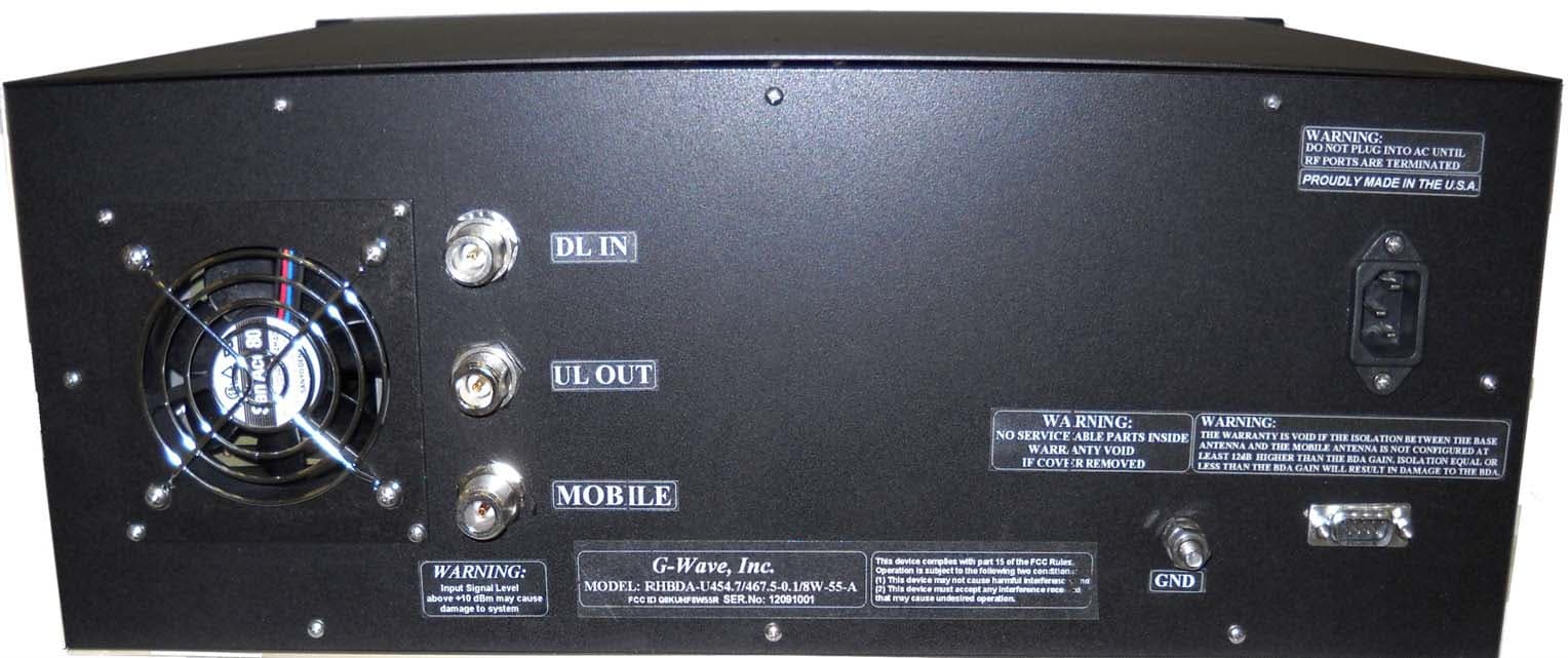
Click to zoom
Application Details
- Equipment Class
- AMP - Amplifier
- Date of Grant
- Oct 15, 2012
- Application Purpose
- Original Equipment
- Date of Application
- Oct 15, 2012
- Equipment Note
- Bi-Directional Amplifier
- Frequency Range
- 465.50000000 - 469.60000000
- Company
- G-Way Solutions, LLC
- Country
- United States
Documents & Files
Document Text
Text extracted from the exhibit documents filed with the FCC. Open a document above to read the original.
Users Manual
INSTALLATION AND OPERATING MANUAL RHBDA-454.7/467.5-0.1/8W-55-A RACK MOUNTABLE BI-DIRECTIONAL AMPLIFIER TABLE OF CONTENTS PARAGRAPH PAGE NO RHBDA OVERVIEW 3 RHBDA BLOCK DIAGRAM DESCRIPTION 3 RHBDA BLOCK DIAGRAM DRAWING (Figure 1) 4 ELECTRICAL SPECIFICATIONS 5 MECHANICAL SPECIFICATIONS 6 ENVIRONMENTAL CONDITIONS 6 RF EXPOSURE WARNING 6 RHBDA CONNECTIONS 7 MECHANICAL OUTLINE DRAWING (Figure 2 & 2a) 8 RHBDA INSTALLATION 9 RHBDA OPERATION 10 FRONT PANEL (Figure 3) 11 BACK PANEL (Figure 4) 11 DIAGNOSTICS GUIDE 12 Page 2 RHBDA OVERVIEW: The RHBDA assembly enhances the coverage area of radio communications in buildings and RF shielded environments. The RHBDA has dual RF paths (Forward/Reverse) to improve coverage in two distinct frequency bands. The unit features low noise figure and wide dynamic range. It is based on a dual duplexed path configuration with sharp out of band attenuation allowing improved isolation between the receiving and transmitting paths. RHBDA BLOCK DIAGRAM DESCRIPTION : Refer to figure 1 for the following discussion. The RHBDA Downlink path receives RF signals from the base station at a Head-end Optic Fiber Unit*, and translates it to an Optical signal. The signal travels over a fiber optic medium, subsequently receives the signal at the Remote Unit, translates it to back to a RF signal then amplifies it, and transmits the signal to the subscriber. The RHBDA Uplink path receives RF signals at the Remote Unit from the subscriber then amplifies it, and translates it to an Optical signal. The signal travels over a fiber optic medium to the Head-end Fiber Optic Unit. The Head-end Fiber Optic Unit receives the signal, translates it to back to a RF signal then transmits the signal to the base station. The Uplink and Downlink occupy two distinct frequency bands. For example, the frequency bands are as follows: 451.7-452.7 & 460.5-464.6 MHz for the Uplink and 456.7-457.7 & 465.5-469.6 MHz for the Downlink. Five Diplexers isolate the paths and route each signal to the proper amplifying channel. A selectable Automatic Level Control (ALC) allows for output power limiting. A variable step attenuator gives 0 – 30 dB of attenuation in 2 dB steps on the Remote Uplink path and two 0 – 30 dB of attenuation in 2 dB steps on the Remote Downlink path. The use of these controls is covered in the “OPERATION” section, later in this document. Optional DC Input Power Option (S1) The RHBDA is equipped with both AC and DC voltage inputs for power operation. This gives the flexibility of powering the RHBDA with either an AC or DC source. If both sources are connected, the RHBDA will automatically select the stronger source for power. Page 3 Figure 1 1. 2. 3. 4. 9. 8. 7. 6. 5. RHBDA BLOCK DIAGRAM RHBDA-454.7/467.5-0.1/8W-55-A 1. Input Downlink Diplexer – has low bandpass insertion loss and high selectivity for two distinct Downlink frequency bands. 2. Downlink Pre-amp’s – are low noise amplifiers that drive the Downlink PA’s and offer 25dB Gain. 3. Downlink PA’s – are power amplifiers with an ALC circuit which offer 30dB Gain. 4. Output Downlink Diplexer - has low bandpass insertion loss and high selectivity for two distinct Downlink frequency bands. 5. Uplink/Downlink Combiner – is Diplexed configured and has low bandpass insertion loss and high selectivity for the Uplink and Downlink frequency bands. 6. Input Uplink Diplexer – has low bandpass insertion loss and high selectivity for two distinct Uplink frequency bands. 7. Uplink Pre-amp’s – are low noise amplifiers that drive the Uplink LPA”s and offer 25dB Gain. 8. Uplink LPA’s – are low power amplifier’s with an ALC circuit which offer 30dB Gain. 9. Output Uplink Diplexer - has low bandpass insertion loss and high selectivity for two distinct Uplink frequency bands. Page 4 ELECTRICAL SPECIFICATIONS : Frequency Range : UL 451.7-452.7 & 460.5-464.6MHz DL 456.7-457.7 & 465.5-469.6MHz Pass band Gain @ min attenuation : 55 dB (Min.) Variable Step Attenuator Range : 0-30 dB (2-dB steps) Pass band Ripple : ±2.0 dB (Typ.) . Noise Figure (Uplink) : 6.0 dB (Typ.) @+25°C at max gain 3rd Order Intercept point Downlink : +52 dBm (Typ.) Output Power (Composite)* Downlink : +31 dBm (Typ.) Uplink : +5 dBm (Typ.) Isolation between Up/Down Link : 100 dB (Min.) Input/ Output Impedance : 50 Ohms *SFDR : 100 dB/Hz 2/3 VSWR (Input/Output) : 1.5: 1 (Max.) Power Supply : 110VAC/1.6Amps : 220VAC/0.8 Amps : 50 to 60 Hz *The Manufacturer's rated output power of this equipment is for single carrier operation. For situations when multiple carrier signals are present, the rating would have to be reduced by 3.5 dB, especially where the output signal is re-radiated and can cause interference to adjacent band users. This power reduction is to be by means of input power or gain reduction and not by an attenuator at the output of the device. Page 5 MECHANICAL SPECIFICATIONS: Size : 19.0 x 13.0 x 7.0 inch : (482.2 x 330.2 x 178 mm) RF Connectors : N-type Female Weight : 36.0 Lbs. (16.4 kg.) approx. ENVIRONMENTAL CONDITIONS : The unit is designed for indoor applications: Operating temperature: - 20°C to + 55°C Storage temperature: - 50°C to + 90°C RF EXPOSURE WARNING In order to satisfy the FCC RF exposure requirements, the RHBDA/antenna installation must comply with the following: The outdoor antenna (Yagi type or similar directional antenna) must be installed so as to provide a minimum separation distance of 0.6 meters (60 cm) between the antenna and persons within the area. (This assumes a typical antenna with gain of [10.1 dBi, VSWR ≤ 1.5:1, Zo= 50 ohms, and a cable attenuation of between 1-10 dB). The indoor antenna (omni directional) must be installed so as to provide a minimum separation distance of 0.6 meters (60 cm) between the antenna and persons within the area. (This assumes a typical wide-beam type antenna with gain of 0-2 dBi, VSWR ≤ 2:1, Zo= 50 ohms, and a cable attenuation of between 1-10 dB). Page 6 RHBDA CONNECTIONS The RHBDA Remote AC power is accepted through a s…
Text truncated - open the document above for the full version.
Cover Letter(s)
G-Way Microwave / G-Wave 38 Leuning Street South Hackensack, NJ 07606 Tel 201-343-6388 Fax 201-343-6390 E-mail [email protected] Website: www.gwaverf.com October 5, 2012 Federal Communications Commission Office of Engineering and Technology 7435 Oakland Mills Rd. Columbia, MD 21046 Subject: Request for Confidentiality Dear Sir or Madam: G-Way Microwave / G-Wave respectfully requests that the schematic diagrams, block diagrams, circuit d escri ptions, and part lists submitted with the application for certification un der FCC ID Q8KUHF8W55R be withheld from public disclosure. This request is made under the provisions of Section 0.457 and 0.459. This product has been developed at considerable expense, and disclosure of this information would place G- Way Microwave / G-Wave at a competitive disadvantage. Thank you for your attention to this matter. Sincerely yours, G-Way Microwave / G-Wave Greg David President 38 Leuning Street South Hackensack, NJ 07606 Tel: (201) 343-6388 Fax: (201) 343-6390 www.gwaverf.com
Internal Photos
Downlink PA
Internal Photos
Low Noise Amplifier/Pre-Amplifier for Uplink & Downlink Back View
Internal Photos
Low Noise Amplifier/Pre-Amplifier for Uplink & Downlink Front View
Internal Photos
Low Noise Amplifier/Pre-Amplifier for Uplink & Downlink Front View in Housing
RF Exposure Info
Prediction of MPE limit at a given distance Equation from page 18 of OET Bulletin 65, Edition 97-01where: S = power density P = power input to the antennaG = power gain of the antenna in the direction of interest relative to an isotropic radiatorR = distance to the center of radiation of the antenna Maximum peak output power at antenna input terminal: 31.23 (dBm) Maximum peak output power at antenna input terminal: 1327.394458 (mW) Antenna gain(typical): 2 (dBi) Maximum antenna gain: 1.584893192 (numeric) Prediction distance: 60 (cm) Prediction frequency: 465 (MHz) MPE limit for uncontrolled exposure at prediction frequency: 0.31 (mW/cm^2) Power density at prediction frequency: 0.046504 (mW/cm^2) Maximum allowable antenna gain: 10.23874059 (dBi) Margin of Compliance: 8.238740586 2 4 R PG S π =
RF Exposure Info
Prediction of MPE limit at a given distance Equation from page 18 of OET Bulletin 65, Edition 97-01where: S = power density P = power input to the antennaG = power gain of the antenna in the direction of interest relative to an isotropic radiatorR = distance to the center of radiation of the antenna Maximum peak output power at antenna input terminal: 5.86 (dBm) Maximum peak output power at antenna input terminal: 3.854783577 (mW) Antenna gain(typical): 10 (dBi) Maximum antenna gain: 10 (numeric) Prediction distance: 60 (cm) Prediction frequency: 465 (MHz) MPE limit for uncontrolled exposure at prediction frequency: 0.31 (mW/cm^2) Power density at prediction frequency: 0.000852 (mW/cm^2) Maximum allowable antenna gain: 35.60874059 (dBi) Margin of Compliance: 25.60874059 2 4 R PG S π =
Test Report
FCC XXX.doc - Date: June, 2011 www.nemko.com Compliance test report ID 220378-1TRFWL Date of issue October 11, 2012 FCC 47 CFR Part 90, Boosters Private Land Mobile Radio Service Applicant G-Way Microwave Product Remote Unit-Dual RF Bi-Directional Amplifier Model RHBDA-U454.7/467.5-0.1/8W-55-A FCC ID Q8KUHF8W55R Nemko Canada Inc., a testing laboratory, is accredited by the Standards Council of Canada. The tests included in this report are within the scope of this accreditation SCC Accredited LAB LAB Accrédité CCN TM Report reference ID:220378-1TRFWL Page 2 of 43 Test location Nemko Canada Inc. 303 River Road Ottawa, ON, K1V 1H2 Canada Test site FCC ID: 176392 (3 m semi anechoic chamber) Telephone +1 613 737 9680 Facsimile +1 613 737 9691 Toll free +1 800 563 6336 Website www.nemko.com Tested by Kevin Rose, Wireless/EMC Specialist Reviewed by October 11, 2012 Andrey Adelberg, Senior Wireless/EMC Specialist Date Limits of responsibility Note that the results contained in this report relate only to the items tested and were obtained in the period between the date of initial receipt of samples and the date of issue of the report. This test report has been completed in accordance with the requirements of ISO/IEC 17025. All results contain in this report are within Nemko Canada’s ISO/IEC 17025 accreditation. Copyright notification Nemko Canada Inc. authorizes the applicant to reproduce this report provided it is reproduced in its entirety and for use by the company’s employees only. Any use which a third party makes of this report, or any reliance on or decisions to be made based on it, are the responsibility of such third parties. Nemko Canada Inc. accepts no responsibility for damages, if any, suffered by any third party as a result of decisions made or actions based on this report. © Nemko Canada Inc. Report reference ID:220378-1TRFWL Page 3 of 43 Table of contents Section 1: Report summary ......................................................................................................................................................... 4 Section 2: Summary of test results ............................................................................................................................................. 5 Section 3: Equipment under test (EUT) details .......................................................................................................................... 6 Section 4: Engineering considerations ....................................................................................................................................... 7 Section 5: Test conditions ........................................................................................................................................................... 8 Section 6: Measurement uncertainty .......................................................................................................................................... 9 Section 7: Test equipment ......................................................................................................................................................... 10 Section 8: Testing data ............................................................................................................................................................... 11 8.1 Clause 2-11-04/EAB/RF Occupied bandwidth ........................................................................................................... 11 8.2 Clause 90.205 Output power ..................................................................................................................................... 18 8.3 Clause 2-11-04/EAB/RF Out of band rejection .......................................................................................................... 19 8.4 Clause 90.210 Conducted and radiated spurious emissions ..................................................................................... 20 8.5 Intermodulation .......................................................................................................................................................... 36 Section 9: Block diagrams of test set-ups ................................................................................................................................ 39 Section 10: EUT photos .............................................................................................................................................................. 40 Section 1 Report summary Report reference ID:220378-1TRFWL Page 4 of 43 Section 1: Report summary 1.1 Applicant and manufacturer G-Way Microwave 38 Leuning Street South Hackensack NJ 07606 United States 1.2 Test specifications FCC 47 CFR 90, Boosters Private Land Mobile Radio Services 1.3 Statement of compliance In the configuration tested the EUT was found compliant. Testing was completed against all relevant requirements of the test standard. Results obtained indicate that the product under test complies in full with the requirements tested. The test results relate only to the items tested. See “Summary of test results” for full details. 1.4 Exclusions None 1.5 Test report revision history Revision # Details of changes made to test report TRF Original report issued Section 2: Summary of test results Report reference ID:220378-1TRFWL Page 5 of 43 Section 2: Summary of test results 2.1 FCC Part 90 test results Part Test description Verdict 90.219 Output power Pass 90.210 Conducted and radiated spurious emissions Pass 90.213 Frequency stability Not applicable 90.219 Use of boosters Pass 2-11-04/EAB/RF Occupied bandwidth Pass 2-11-04/EAB/RF Out of band rejection Pass Notes: The EUT doesn’t change the frequency. Section 3 Equipment under test (EUT) details Report reference ID:220378-1TRFWL Page 6 of 43 Section 3: Equipment under test (EUT) details 3.1 Sample information Receipt date September 18, 2012 Nemko sample ID number 1 3.2 EUT information Product name G-Wave PBS Booster…
Text truncated - open the document above for the full version.
Contact Information
Applicant
Sharon David(Marketing Director)
Technical Contact
G-Way Microwave / G-WaveDino Giordano
[email protected]2013436388
38 Leuning Street · South Hackensack, New Jersey · United States
Non-Technical Contact
G-Way Microwave / G-WaveMargaret Argento
[email protected]2013436388
Test Firm
Nemko Canada IncStuart Beck
Technical Specifications
| # | Rule Parts | Frequency Range | Power Output | Emission | Tolerance |
|---|---|---|---|---|---|
| 4 | 9 | 465.5 MHz - 469.6 MHz | 1.33 W | F3E | Amp |
Other Applications from G-Way Solutions, LLC

Q8KUHF3680AB
Jul 17, 2015Booster
Equipment Class
B9B - Part 90 Class B Industrial Booster (non-SMR)
Q8KUHF3680R
Jul 17, 2015Booster
Equipment Class
B9B - Part 90 Class B Industrial Booster (non-SMR)
Q8KUHF3680N
Jul 17, 2015Booster
Equipment Class
B9B - Part 90 Class B Industrial Booster (non-SMR)
Q8KCELLPCS2W80N
Mar 28, 2015RigBooster PRO, Dual Band Outdoor BDA
Equipment Class
B2I - Part 20 Industrial Booster (CMRS)
Q8KCELLPCS3380AB
Mar 28, 2015Dual Band Bi-Directional Amplifier
Equipment Class
B2I - Part 20 Industrial Booster (CMRS)