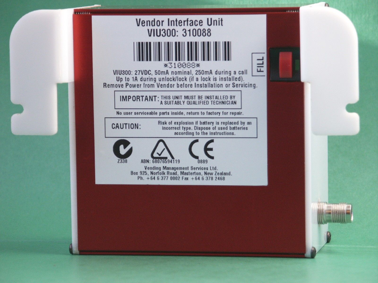
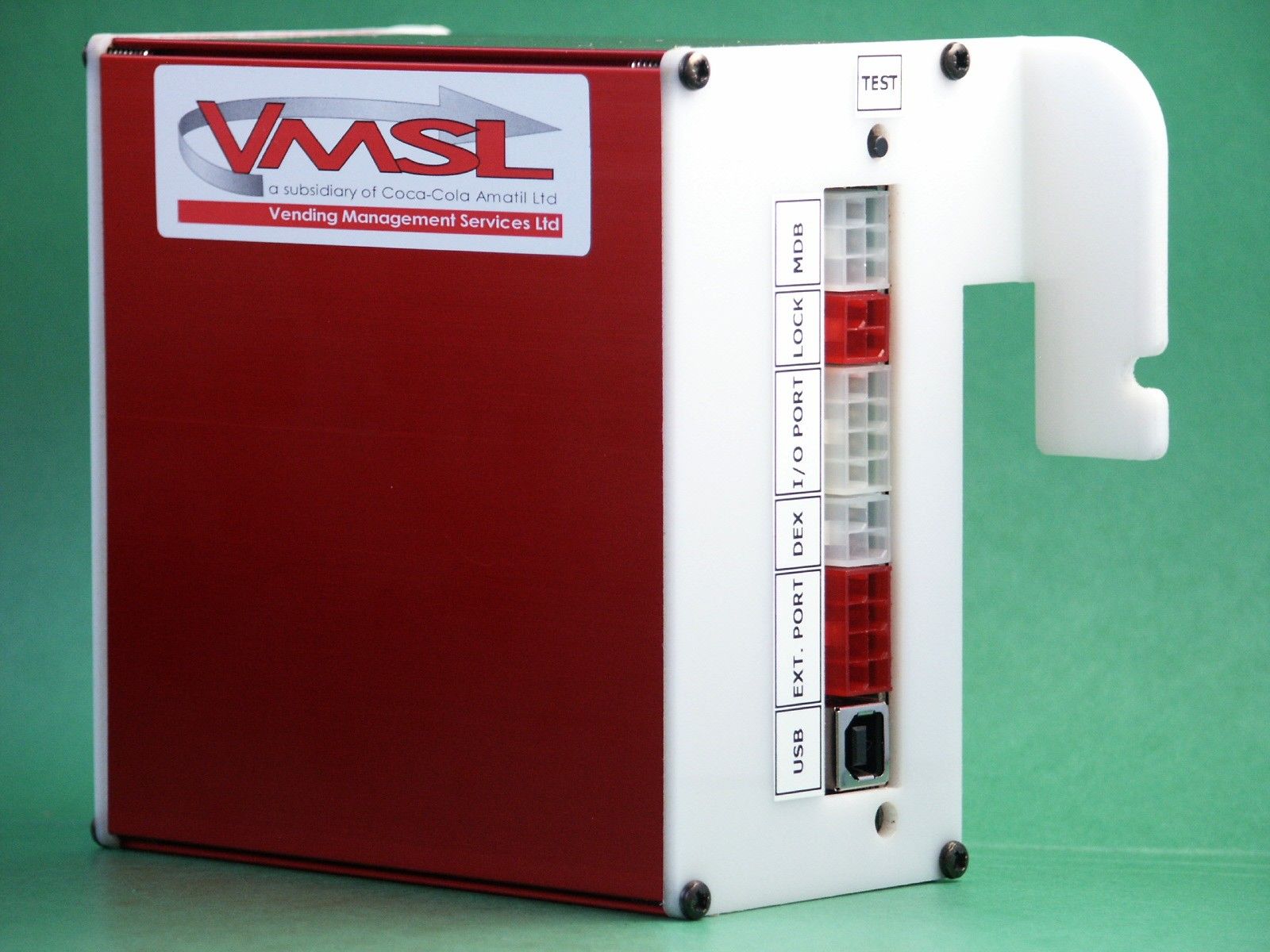
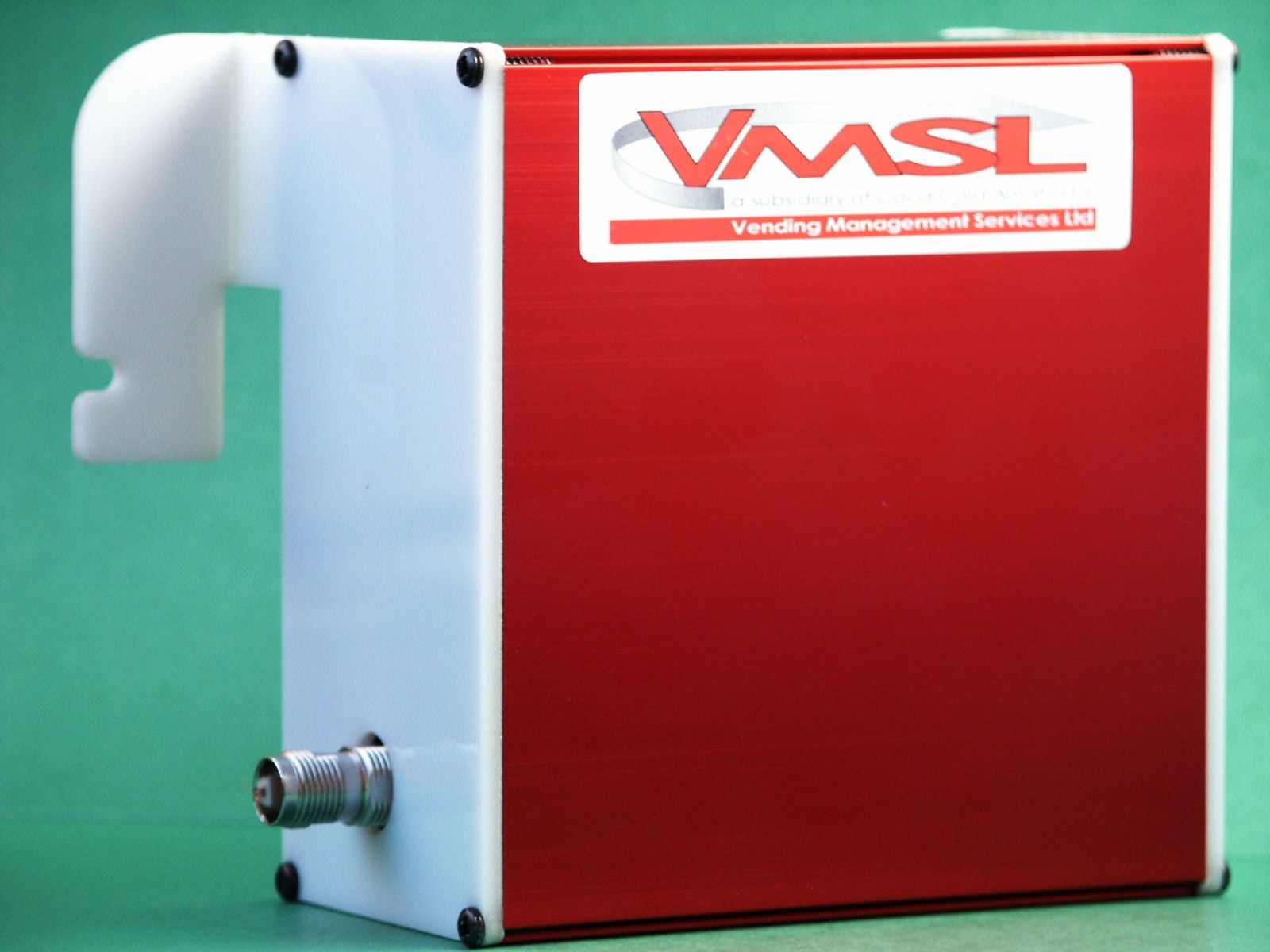
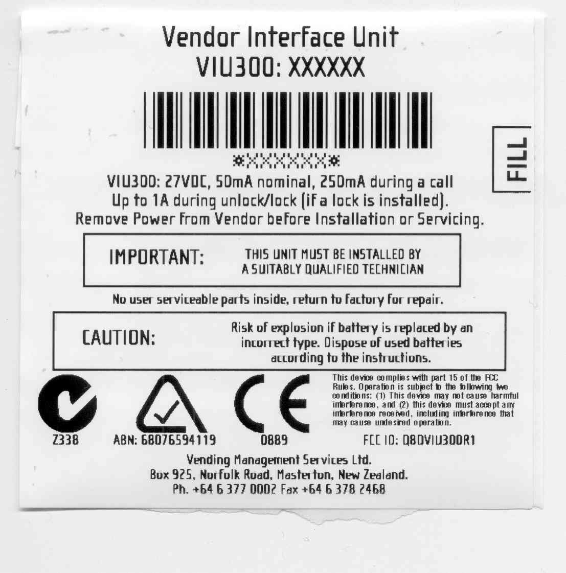
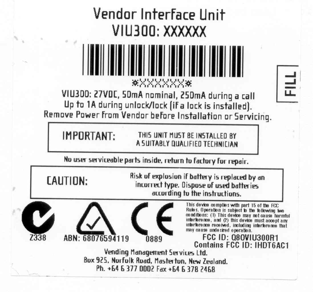
Q8OVIU300R1Vendor Interface Unit
Vending Management Services Ltd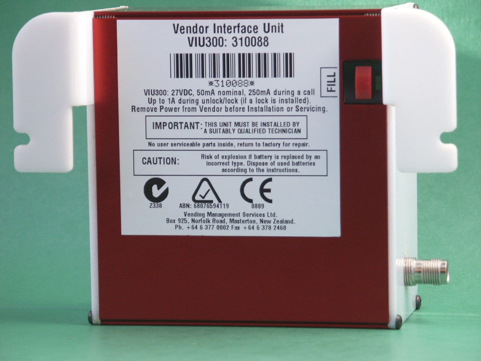
Click to zoom
Application Details
- Equipment Class
- PCB - PCS Licensed Transmitter
- Date of Grant
- Jun 21, 2004
- Application Purpose
- Original Equipment
- Date of Application
- May 16, 2004
- Equipment Note
- Vendor Interface Unit
- Frequency Range
- 1850.20000000 - 1909.80000000
- Country
- New Zealand
Documents & Files
Document Text
Text extracted from the exhibit documents filed with the FCC. Open a document above to read the original.
Users Manual
APPLICANT: MOTOROLA, INC.FCC ID: IHDT6AC1 EXHIBIT 8 INSTRUCTION MANUAL A preliminary draft copy of the Users Manual follows. RF exposure information is located in section 1.3. APPLICANT: MOTOROLA, INC.FCC ID: IHDT6AC1 Exhibit 8 1 D15 – Developer Guide – 1 st draft 1. Introduction Product description The D15 model Main application SAR Requirements. 2. Installation Mechanical description Connections 3. Pin description & main Functionality Pin description of connectors per model Different communication & application 4. Modes of Operation On/Off process include time diagram Voice connection Full flow control data call Soft GSM Operation 5. Design Consideration Power supply Antenna Data level (VOH, VOL) Flex cable & external SIM Connector Environmental 6 Testing & service How to test a unit in a voice call How to test a unit in a data call How to test a unit in a soft GSM call How to test RF features Desense test 7. Appendix 1st. Specification 2nd. A list of AT command 3rd. Desense test APPLICANT: MOTOROLA, INC.FCC ID: IHDT6AC1 Exhibit 8 2 1. Introduction 1.1 Product Specification – See in Appendix bellow. To add a note thal all the Data/Audio/SIM signals are compatible with D10 User Device D10 30 pin FC D15 User Device 36 pin FC 3 lines removed from each side 1.2 D15 Models: • D15 DV (DV= Data & Voice) Standard. APPLICANT: MOTOROLA, INC.FCC ID: IHDT6AC1 Exhibit 8 3 • D15 DV Slim • D15 DVG Slim (DVG= Data, Voice, GPS) • D15 DV Board only (Vertical version & Horizontal version) APPLICANT: MOTOROLA, INC.FCC ID: IHDT6AC1 Exhibit 8 4 1.3 SAR Requirements User Operation Do not operate your telephone when a person is within 8 inches (20 centimeters) of the antenna. A person or object within 8 inches (20 centimeters) of the antenna could impair call quality and may cause the phone to operate at a higher power level than necessary and expose that person to RF energy in excess of that established by the FCC RF Exposure Guidelines. IMPORTANT The telephone must be installed in a manner that provides a minimum separation distance of 20 cm or more between the antenna and persons to satisfy FCC RF exposure requirements for mobile transmitting devices. Antenna Installation IMPORTANT: To comply with the FCC RF exposure limits and satisfy the categorical exclusion requirements for mobile transmitters, the following requirements must be met: 1. A minimum separation distance of 20 cm must be maintained between the antenna and all persons. 2. The transmitter effective radiated power must be less than 3.0 Watts ERP (4.9 Watts or 36.9 dBm EIRP). This requires that the combination of antenna gain and feed line loss does not exceed 16 dBi. APPLICANT: MOTOROLA, INC.FCC ID: IHDT6AC1 Exhibit 8 5 2. Installation – See details in PRD. Configuration 1 with d10 mounting Configuration 1 Configuration 1 with narrower mounting with narrower mounting APPLICANT: MOTOROLA, INC.FCC ID: IHDT6AC1 Exhibit 8 6 Configuration 1 with narrower mounting Configuration 2 Configuration 2 APPLICANT: MOTOROLA, INC.FCC ID: IHDT6AC1 Exhibit 8 7 Configuration 2 Configuration 2 APPLICANT: MOTOROLA, INC.FCC ID: IHDT6AC1 Exhibit 8 8 APPLICANT: MOTOROLA, INC.FCC ID: IHDT6AC1 Exhibit 8 9 3. Pin description & main Functionality 3.1 Standard model & Slim model The available functionality in these models are the follow: Data & Voice (D10 Replacement & Slim) - Connections D15 Main Process. Uart #1 RS232 port User logic Power supplies Main PWR Audio Data port EXT_SIM DSC General Data purposes DSC bus 3.1.1 Function available in the user connector – 36 pin ZIF • VCC input. 3.0 to 6Vdc • Full RS232 - 9 pins. TXD, RXD, RTS,CTS,DSR,DTR,DCD,RI at 5V levels. • External SIM connections.SIM Clock, SIM reset, SIM I/O, SIM VCC,SIM PD • DSC bus.DSC_EN, Downlink, Uplink – Motorola proprietary us. • Audio In/Out.Audio out and On/Off in the same pin, audio in Signal and analog ground. • Man_Test line.Used to detect standard Motorola accessories. • TS line (mobport).Used to turn on the radio. • TX_EN line.This line is an indication when the radio is transmitting. Note: 1. The Audio Out line is used to send out the detected audio and as a toggle On/Off pin. APPLICANT: MOTOROLA, INC.FCC ID: IHDT6AC1 Exhibit 8 10 2. The TS line is used to turn On the units by any transaction from Low to high in this pin. 3.1.2 Connector pin out Pin #FunctionPin #Function 1 TX_EN19SIM I/O 2 N.U.20SIM CLK 3 N.U.21TS 4 TXD22DSC_EN 5 RXD23Down Link 6 DTR24Up Link 7 DCD25Analog Ground 8 RTS26Ground 9 CTS27Ground 10 DSR28Ground 11RI29Ground 12 Manual_Test30VCC 13 Audio In31VCC 14 On/Off + Audio Out32VCC 15 N.U. 33VCC 16SIM _PD 34NU 17SIM _VCC 35NU 18SIM_Reset 36NU APPLICANT: MOTOROLA, INC.FCC ID: IHDT6AC1 Exhibit 8 11 3.2 D15 with GPS The available functionality in this models are the follow: Data & Voice + GPS model - Connections GPS (M12) D15 Main Process. GPS Process. Uart #1 RS232 port User logic Power supplies GPS Ant PWR 1PPS RX Diff Main PWR Audio Data port EXT_SIM DSC GPS purposes General Data purposes DSC bus Reg 3V 3.2.1 Function available in the user connector – 36 pin ZIF • VCC input. 3.0 to 6Vdc • Full RS232 - 9 pins. TXD, RXD, RTS,CTS,DSR,DTR,DCD,RI at 5V levels. • External SIM connections.SIM Clock, SIM reset, SIM I/O, SIM VCC,SIM PD • DSC bus.DSC_EN, Downlink, Uplink – Motorola proprietary us. • Audio In/Out.Audio out and On/Off in the same pin, audio in Signal and analog ground. • Man_Test line.Used to detect standard Motorola accessories. • TS line (mobport).Used to turn on the radio. • TX_EN line.This line is an indication when the radio is transmitting. • GPSTXD & RXD in 3V levels, 1PPS, APPLICANT: MOTOROLA, INC.FCC ID: IHDT6AC1 Exhibit 8 12 RTCM, Antenna power Note: 1. The Audio Out line is used to send out the detected audio and as a toggle On/Off pin. 2. The TS line is used to turn On the units by any transaction from Low to high in this pin. 3. The GPS is mounted on top of theD15 and receive power from the D15 but it is a stand-alone unit. The GPS is working from 3V and th…
Text truncated - open the document above for the full version.
Users Manual
VMSL VENDING MANAGEMENT SERVICES LTD Technical Information + + + + Vendware™ EVIU300™ Vendor Interface Unit Installation Instructions CONTACT DETAILS VMSL 25 Norfolk Road PO Box 925 Masterton New Zealand www.vmsl.co.nz tel +64 (6) 377 0002 fax+64 (6) 378 2468 support desk:0800 106 109 (NZ) 1800 060 514 (AUS) ©Copyright 2004 Vending Management Services Limited. PO Box 925, Masterton, New Zealand No part of this document may be copied or reproduced in any form or by any means without prior written consent of Vending Management Services Limited. The information in this document is subject to change without notice and does not represent a commitment on the part of the vendor. Vending Management Services Limited assumes no responsibility for any errors that may appear in the document. + + TABLE OF CONTENTS Regulatory Declarations1 Warning2 Compatibility2 Preparation3 Equipment Required For Installation3 Viu300 Main Board4 Connector Layout Of Circuit Board4 Sim Card Installation5 Harness Installation6 Dex Harness6 Mdb Harness7 Antenna Installation8 Initial Call Through Tests9 Lock Installation9 Final Checks9 Troubleshooting10 Electrical Specifications11 + + Technical Information VIU300™ Installation Instructions Vendor Interface Unit REGULATORY DECLARATIONS: –This unit is only to be serviced by suitably qualified personnel. –There are no user serviceable parts within the VIU. –All power must be removed from the vending machine and VIU prior to any servicing, installation or de-installation. –Caution, risk of explosion if battery is replaced with an incorrect type. Dispose of used batteries according to the instructions. WARNING The Motorola G18 GSM Radio Module used in the VIU300 may produce electromagnetic fields that are capable of igniting some gases and vapours if present in the vicinity of the device. To avoid risk of igniting flammable gasses and vapours, always use and install this device in a well ventilated area away from all Type IIA gases and gas storage facilities. The device may operate without warning and contains battery backup to ensure operation even during mains power failure. Disable the backup battery and disconnect all mains power before releasing all Type IIA gasses near this device. Ignition of Flammable Atmospheres Hazard + + page 2 + + COMPATIBILITY This Instruction covers the installation of the Vendor Interface Unit (VIU) with the following specifications. VIU Unit Specification: VIU300 unit with integral Motorola G18 GSM/GPRS Modem module The vending machine specifications –∑ Electronically Controlled (uses a VMC) –∑ MDB compatible ( EVS 2.2 or later) –∑ DEX compatible ( EVS 2.2 or later) Preparation Before commencing the installation it is necessary to confirm that the VIU will call in from the machine site. –Check the signal strength with an ordinary Cell-phone by reading the number of “signal bars” that are present, or by making a call from the site. Note that this should be done from a phone connected to the same GSM network as the VIU being installed –Make a quick check of the machine to ensure that it is compatible with the VIU To perform a pre-install call in, use the following steps –Ensure that the machine is powered down –Insert the SIM card in the modem – refer to section on “Installation of SIM Card” –Connect the antenna harness to the VIU and the antenna, temporarily position the antenna as close as practicable to the place were it is to be mounted –Connect the MDB harness – refer to the section on “MDB Harness Installation” –Connect the DEX harness – refer to the section on “DEX Harness Installation” –Power up the vending machine and wait for the initialisation sequence to finish –Press the Test Button, the green LED (Light Emitting Diode) on the fill Button should flash then stay on solid until the call is completed –Contact the Support Centre to verify that the call is successful + + + + page 3 page 4 Equipment required for Installation –VIU-VIU300 Unit –GSM SIM Card-SIM may be pre-installed in the unit. –MDB Harness -LM-VIU050 –DEX Harness-LM-VIU026 –Antenna Kit-VA-ANTG-035 –Electronic Lock-Optional OTHER REQUIRED ITEMS ARE –13/32” Pilot point Drill (or standard 10.0mm Drill Bit) –VIU support brackets (Specific to machine type) VIU300 Main Board CONNECTOR LAYOUT OF CIRCUIT BOARD Connector locations on VIU300 Unit + + + + + + SIM Card Installation –The SIM card may be pre-installed in the VIU prior to issue. Please check before proceeding with this part of the instruction. –Installation of the SIM card will require removal of the end panel of the VIU300 unit. –Undo the 4 screws holding the end panel with the antenna connector to the VIU300 case body. –Undo the antenna connector retaining nut from the end panel. –Remove the end panel, exposing the modem unit SIM slot. –Carefully slide the SIM card into the SIM card slot of the modem unit with the SIM card contacts facing the body of the modem. –Refit the end panel with the 4 screws and the antenna retaining nut. Do not over tighten. page 5 Harness Installation DEX HARNESS –Plug the DEX connector into the DEX output of the Vending Machine Controller (VMC) –Run the harness to the VIU and connect –Secure the harness with plastic cable ties + + page 6 Connects to DEX output on VMC (Phono plug shown, but a Flat plug version is also available) This 4 way Molex Minifit Jr connector goes to the DEX port on VIU300 MDB HARNESS –POWER DOWN THE VMC to prevent damage to the VMC and Coin mechanism when connecting and disconnecting the MDB harness. –Interrupt the Power harness (MDB) between the Coin Mechanism and the VMC –Connect the VIU Power harness (MDB harness) in line with the Coin Mechanism and the VMC. The two 6 – pin connectors on the loom are configured so that it is difficult to make an incorrect connection. + + page 7 6 – pin female plug Connect to MDB input of VIU300 6 – pin female plug. Connect to the harness from the VMC 6 – pin male plug. Connect to the harness from the Coin Mechanism Antenna Installa…
Text truncated - open the document above for the full version.
Attestation Statements
May 30, 2000 SAR Test Report for Motorola Mobile Phone FCC ID IHDT6AC1. Prepared by: Paul Moller, Principal Staff Engineer Motorola Personal Communications Sector Product Safety Laboratory Libertyville, Illinois The Motorola Personal Communications Sector Product Safety & Compliance Laboratory has evaluated the Mobile Phone FCC ID IHDT6AC1 for the need to conduct SAR evaluation. The appropriate standards are Federal Communications Commission section 47 CFR § 2.1091, the ANSI/IEEE C95.1 1992 and the NCRP Report Number 86. All of these standards have the same exclusionary requirements. Due to the design and installation of this product, it qualifies for the exclusion called out in Federal Communications Commission section 47 CFR § 2.1091 titled “Radiofrequency radiation exposure evaluation: mobile devices.” Based on the installation of the transceiver and the antenna, the transmitters radiating structure is more than 20 centimeters from the user. Thus, the Mobile Phone FCC ID IHDT6AC1 is a “mobile device” as defined in section § 2.1091 paragraph (b). Since the transceiver’s transmit frequency is above 1.5GHz and its ERP with the specified antenna is below 3 Watts, the Mobile Phone FCC ID IHDT6AC1 is “categorically excluded from routine environmental evaluation” per paragraph (c), and thus SAR evaluation is not required. Thus, the Mobile Phone FCC ID IHDT6AC1 does not require SAR evaluation.
Cover Letter(s)
APPLICANT: MOTOROLAFCC ID: IHDT6AC1 Exhibit 13 June 1, 2000 CONFIDENTIALITY REQUEST CONTAINED WITHIN Federal Communications Commission Authorization and Evaluation Division 7435 Oakland Mills Road Columbia, Maryland 21046 Re: Application for PCS Transceiver Certification Gentlemen: Application: Motorola, Inc., Personal Communications Sector, 600 N. U.S. Highway 45, Libertyville, Illinois 60048-1286 herein submits: Application for Equipment Authorization (FCC Form 731-October 1992 with integrated Fee Processing Form, Fee Codes EFT and EBC), application fee in the amount of $610, and Exhibits; for Certification of a PCS Transceiver, FCC ID: IHDT6AC1. Motorola is also the manufacturer of this equipment. Confidentiality: Pursuant to Section 0.459 of the Commission's rules (CFR 47), Motorola requests confidentiality for portions of the material contained in this application and that the identified material be withheld from public inspection following the grant of this authorization. This material contains Motorola's trade secrets and confidential information that Motorola does not customarily release to the public and which is otherwise not generally available to the public. Confidentiality is requested for the following exhibits: • Exhibit 4 Block Diagrams • Exhibit 5 Schematics • Exhibit 12 Operational Description Description: This equipment is a GSM Embedded Module, which operates in the 1900 MHz PCS band. It can transfer data or voice over a GSM network. Model differences are dependent upon housing and external connector variations. Contact Information: Please contact me by telephone at (847) 523-6167 or by e-mail ([email protected]), if there are questions or additional information needed concerning this filing. Regards, Andrew J. Bachler FCC Liaison Personal Communications Sector 600 N. U.S. Highway 45 Libertyville, IL 60048-5343
Cover Letter(s)
25 Norfolk Road P.O. Box 925 Masterton New Zealand Tel: +64-6-377-0002 Fax: +64-6-378-2468 www.vmsl.co.nz Federal Communications Commission Authorization and Evaluation Division 7435 Oakland Mills Road Columbia, Maryland 21046 USA Re: Application for Low Power Communications Device under Part 15 Gentlemen, Application: Vending Management Services Ltd (VMSL) of Norfolk Rd, Masterton, New Zealand herein submits application and exhibits for the certification of a low powered communications device FCC ID Q8OVIU300R1. This device incorporates an approved PCS transceiver manufactured by Motorola Inc (FCC ID IHDT6AC1). VMSL is the manufacturer of the remainder of the device. Confidentiality Pursuant to Section 0.459 of the commission’s rules (CFR 47), VMSL requests confidentiality for potions of the material contained in this application and that the identified material be withheld from public inspection following the grant of this authorization. This material contains the trade secrets and confidential information of VMSL and our supplier Motorola that is not customarily released to the public and is not generally available to the public. Confidentiality is requested for • Block Diagrams • Schematics • Operational Descriptions Description This equipment is a telemetry device for collecting and reporting data from vending machines. Data is collected from the vending machine using a serial data interface and transferred to external processing systems. The delivery of data to external processing systems is achieved using the incorporated Motorola GSM embedded module operating on the 1900MHz PCS band (FCC ID IHDT6AC1). Installation of the device is by trained personnel and the device is designed for automatic operation. Contact Information Please contact me by telephone (+6421350706) or by e-mail ([email protected] ) if there are any questions or additional information needed concerning this filing. Regards Chris Cameron Product Delivery Manager
Internal Photos
APPLICANT: MOTOROLA, INC. FCC ID: IHDT6AC1 EXHIBIT 9 Typical Unit (Bottom View Shields Removed) Typical Unit (Top View Shields Removed) Note: External connector type varies depending upon model
Parts List/Tune Up Info
APPLICANT: MOTOROLA, INC.FCC ID: IHDT6AC1 EXHIBIT 10 TRANSCEIVER ADJUSTMENTS/TUNE-UP PROCEDURE There are no user accessible adjustments or tuning in this portable cellular transceiver. All necessary adjustments and tuning are performed during manufacture of the product. Any adjustments or tuning after service or repair are done as part of that process as special equipment is required to perform such adjustments.
Test Report
Parkside Laboratories GLOBAL TESTING, CALIBRATION & CERTIFICATION SERVICES ELECTRICAL EMC ENVIRONMENTAL APPROVED BY: TESTED BY: PREPARED BY: Manuel Shimasaki Sherif Antoun Clare Rochford IANZ Signatory EMC Compliance Engineer Technical Writer 10 VANADIUM PLACE, PO BOX 9194, MIDDLETON, CHRISTCHURCH 8002, NEW ZEALAND Page 1 of 11 TEL: +64 3 339 1670 FAX: +64 3 339 1671 EMAIL: [email protected] INTERNET: www.parksidelabs.com All tests reported herein have been performed in accordance with the laboratory’s IANZ approved scope of accreditation. 363 International Accreditation New Zealand (IANZ) has a Mutual Recognition Arrangement (MRA) with the National Association of Testing Authorities (NATA), Australia, such that both organisations recognise accreditations by IANZ and NATA as being equivalent. Users of test reports are recommended to accept test reports in the name of either accrediting body. Laboratory Test Report Report No.: 8086A-00 This report may not be reproduced except in full. Date Issued: 26 April 2004 It contains no corrections or erasures. SUBJECT: Vendor Interface Unit Model: VIU300: 71740 Rating: 27 V d.c., 50 mA nominal REQUESTED BY: Vending Management Services Limited 25 Norfolk Road P.O. Box 925 Masterton NEW ZEALAND INSTRUCTIONS: ß Test compliance for compliance with AS / NZS CISPR 22: 2002 “Information technology equipment. Radio disturbance characteristics. Limits and methods of measurement”. ß Test for compliance with BS EN 55022: 1998 (CISPR 22: 1997) “Information technology equipment. Radio disturbance characteristics. Limits and methods of measurement” excluding telecommunication ports. ß Test for compliance with the RF emission requirements of the Federal Communications Commission (FCC 47 Part 15: 2002). CONTENTS: General Test Specification Date of test Description Results: AS / NZS CISPR 22:2002 / BS EN 55022:1998 (CISPR 22: 1997) Scan: Radiated Emissions 30 MHz – 1 GHz SUMMARY: All test results in this report in relation to the Vendor Interface Unit, Model VIU300: 71740 confirmed that the specimen Complied with the relevant provisions of AS / NZS CISPR 22:2002, BS EN 55022: 1998 (CISPR 22:1997) and FCC 47 Part 15: 2002 for Class A. Parkside Laboratories This report may not be reproduced except in full. SIGNATORY: Page 2 of 11 It contains no corrections or erasures. Report No.: 8086A-00 Date Issued 26 April 2004 GENERAL a) As detailed in this report, one specimen of the Vendor Interface Unit, Model VIU300: 71740 was received for testing. b) The results detailed in this report are based on the specimen submitted by the manufacturer under Purchase Order Number 4000087. c) The specimen was tested for compliance with Electromagnetic Interference (EMI) in accordance with BS EN 55022: 1998 (CISPR 22: 1997), FCC 47 Part 15: 2002 and AS / NZS CISPR 22: 2002. d) All testing was carried out under the following environmental conditions, unless otherwise noted: Ambient temperature 15 °C to 35 °C Relative humidity 30 % to 60 % Atmospheric pressure 86 kPa to 106 kPa. e) Note: N/R = Not Relevant to design assessed, N/T = Not Tested at manufacturer’s request, EUT = Equipment Under Test, DNC = Did Not Comply. f) The reported expanded uncertainties (U) listed below are based on standard uncertainties multiplied by a coverage factor k = 2, and define an interval ±U providing a level of confidence of approximately 95 %. The uncertainty calculations have been carried out in accordance with IANZ requirements. (i) Conducted EMI Measurement 0.15 – 30 MHz ± 3 dB (RFI Voltage Test) (ii) Radiated EMI Measurement 30 – 1000 MHz ± 4.6 dB g) For radiated emission measurements, maximum peak disturbance scans were performed over the entire frequency range of 30 MHz to 1 GHz while varying the products azimuth 0° to 360° and the antenna height, from 1 to 4 meters with both horizontal and vertical polarities. The disturbance scans maximum disturbance points were analysed. The 9 maxima were then subjected to a Quasi-Peak analysis for > 1 s at each point where the exact azimuth, height, polarity and frequency of the disturbance occurred. All 9 quasi-peak points were manually verified and ambient signal results removed. h) Clause 15.107 part (e) & Clause 15.109 (g) of the “Code of Federal Regulations” states that by meeting the requirements of BS EN 55022: 1998, compliance with the FCC limits has been demonstrated. BS EN 55022:1998 is equivalent to CISPR 22: 1997. Parkside Laboratories This report may not be reproduced except in full. SIGNATORY: Page 3 of 11 It contains no corrections or erasures. Report No.: 8086A-00 Date Issued 26 April 2004 TEST SPECIFICATION Australian / New Zealand Standard AS / NZS CISPR 22: 2002 (Including No Amendments) “Information technology equipment. Radio disturbance characteristics. Limits and methods of measurement.” British Standard BS EN 55022: 1998 (CISPR 22: 1997) (Including One Amendment) “Information technology equipment. Radio disturbance characteristics. Limits and methods of measurement.” FCC 47 Part 0 to 19 :2002 “Federal Communications Commission & code of federal regulations.” These specifications were applicable at the time of testing. DATE OF TEST Testing was completed on 6 April 2004. Parkside Laboratories This report may not be reproduced except in full. SIGNATORY: Page 4 of 11 It contains no corrections or erasures. Report No.: 8086A-00 Date Issued 26 April 2004 DESCRIPTION The Vendor Interface Unit, Model VIU300: 71740 was rated at 27 V d.c., 50 mA nominal, 250 mA during a call and up to 1 A during lock/unlock. The case was made of a stainless steel like finishing with black plastic sides to hold the enclosure together. The EUT had wall-mounting supports on the back of the unit. The Vendor Interface Unit, Model VIU300: 71740 had a red fill button on the front upper right corner of the unit, with a green LED below it. On the right side of the enclosure was MDB, Lock, I/O port, DEX, ext port and USB connections. On the same side of the enclosure …
Text truncated - open the document above for the full version.
Test Report
APPLICANT MOTOROLA INC. FCC ID:IHDT6AC1 Exhibit 6 1 TEST REPORT Exhibit Summary: EXHIBIT6 contains worst case measurement data that was taken on five different D15 Module configuration, listed below: 1. D15 DV (DV= Data & Voice) Standard 2. D15 DV Slim 3. D15 DVG Slim (DVG= Data, Voice, GPS) 4. D15 DV Board only (Vertical version) 5. D15 DV Board only (Horizontal version) Contents: RF Power Output.....................................................6A Final Amplifier Voltages and Currents......................6B Radiated Spurious Emission...................................6C Occupied Bandwidth...............................................6D Conducted Spurious Emissions...............................6E Frequency Stability..................................................6F APPLICANT MOTOROLA INC. FCC ID:IHDT6AC1 Exhibit 6A 2 RF Output Power Exhibit Summary: EXHIBIT 6A contains both average and peak output powers for the mobile station. The peak power results are presented in tabular form which illustrates the deviation in power with respect to the average value. In all cases, the peak output power is within the required mask (this mask is specified in the JTC standards, TIA PN3389 Vol. 1, Chap. 7, and is not an FCC requirement). Contents: Method of Measurement..............................................2 Measurement Limit......................................................2 Power Measurements..................................................2 Method of Measurement: 1.Setup the mobile station for maximum output power with pseudo random data. 2.Use HP 8991A Peak Power Analyzer to obtain peak and average output power levels. 3.Repeat measurements for carrier frequencies at 1850.2 MHz, 1880.2 MHz, and 1909.8 MHz. Channels 512, 662, and 810 respectively (bottom, middle, and top of operational frequency range). Measurement Limits: Table 6.1 PowerNominal Peak StepOutput PowerTolerance (dBm)(dB) 030+/- 2 Power Measurements: Table 6.2 FrequencyPowerPeakAverage (MHz)StepOutput PowerOutput Power (dBm)(dBm) 1850.2029.920.87 1880.2029.520.47 1909.8028.7519.72 APPLICANT MOTOROLA INC. FCC ID:IHDT6AC1 Exhibit 6B 3 Final Amplifier Voltage and Currents Exhibit Summary: EXHIBIT 6B below contains the voltages and currents applied to the TX Driver and TX Final Power Amplifier for the entire mobile station operating power range. PowerPowerPowerVcc (Q331)Ic (Q331)Vdd (Q380)Id(Q380) StepOutputOutput Spec. (dBm)Meas. (dBm)(VDC)(mA Peak)(VDC)(mA RMS) 0 30 +/-229.94.7244.7290 128 +/-326.724.7224.7260 226 +/-225.14.7184.7240 324 +/-222.954.7164.7230 422 +/-3214.7144.7210 520 +/-319.154.7134.7200 618 +/-317.254.7114.7190 716 +/-315.254.7104.7190 814 +/-313.34.784.7180 912 +/-411.34.774.7180 1010 +/-48.94.75.54.7180 118 +/-47.184.754.7175 126 +/-46.194.74.54.7170 134 +/-45.554.74.34.7170 142 +/-44.14.74.34.7170 150 +/-43.34.74.34.7170 APPLICANT MOTOROLA INC. FCC ID:IHDT6AC1 Exhibit 6C 4 Radiated Spurious Emissions Exhibit Summary: EXHIBIT 6C contains measurement data pertaining to radiated spurious emissions. Contents: Introduction...........................................................................4 Purpose................................................................................4 Radiated Emissions Test Setup............................................5 Radiated Emission Test Procedure......................................5 Test Equipment Utilized for the Radiated Emissions Test....6 Measurement Results...........................................................6 Emission Plot........................................................................7 Appendix A: Sample Calculations.........................................8 Appendix B - Test Equipment...............................................9 Introduction The following steps outline the procedure used to measure the radiated emissions from the mobile station. The data were taken at L. S. Compliance Inc. Measurement Facility ID Number: 31040/ SIT Located at W66 N220 Commerce Court, Cedarburg, Wisconsin 53012. Test Report Number: 300143 Dates of Testing: March 27-29, 2000. On March 27-29, 2000, a series of Radiated Emissions tests were performed on a sample model of the Motorola D15 family of modules for Cellular Telephone. These tests were performed using the test procedures outlined in ANSI C63.4-1992 for intentional radiators, as called for in section 2.1033 for a type accepted device, and in accordance with the limits set forth in FCC Part 15.109, Part 24, and 22.917e. These tests were performed by Kenneth L. Boston, PE, of L. S. Compliance, Inc. and witnessed by Reuven Konevky of Motorola. Purpose The above mentioned tests were performed in order to determine the compliance of the test sample with limits contained in various provisions of Title 47 CFR, including: 2.10512.105315.10924.238 22.917 All radiated emissions tests were performed to measure the emissions in the frequency bands described by the above sections, and to determine whether emissions are below the limits established by the above sections. These tests were APPLICANT MOTOROLA INC. FCC ID:IHDT6AC1 Exhibit 6C 5 performed in accordance with the procedure described in the American National Standard for methods of measurement of Radio-Noise Emissions from Low-Voltage Electrical and Electronic Equipment in the Range of 9 kHz to 40 GHz (ANSI C63.4- 1992). Another document used as reference for the EMI receiver specification is the International Special Committee on Radio Interference (CISPR) number 16-1 (1993). Radiated Emissions Test Setup The test sample was operated within the 3 meter Semi-Anechoic, FCC listed chamber located at L.S. Compliance in Cedarburg, WI. The sample was placed on an 80cm high small wooden pedestal, centered on the flush-mounted 2m diameter metal turntable. The test sample was configured to run in a continuous transmit mode during the Radiated measurements. The test sample was set to operate on one of three standard channels within the Cellular frequency assig…
Text truncated - open the document above for the full version.
Contact Information
Applicant
Toby J Mills(Risk & Intellectual Property Manager)
Test Firm
Independent Test Laboratories LimitedManuel Shimasaki
Technical Specifications
| # | Rule Parts | Frequency Range | Power Output | Emission | Tolerance |
|---|---|---|---|---|---|
| 1 | 24E | 1.85 GHz - 1.91 GHz | 980.00 mW | 250KGXW | 0.1000000000 ppm |