Q8VDX1BHF Amateur
Emtron North America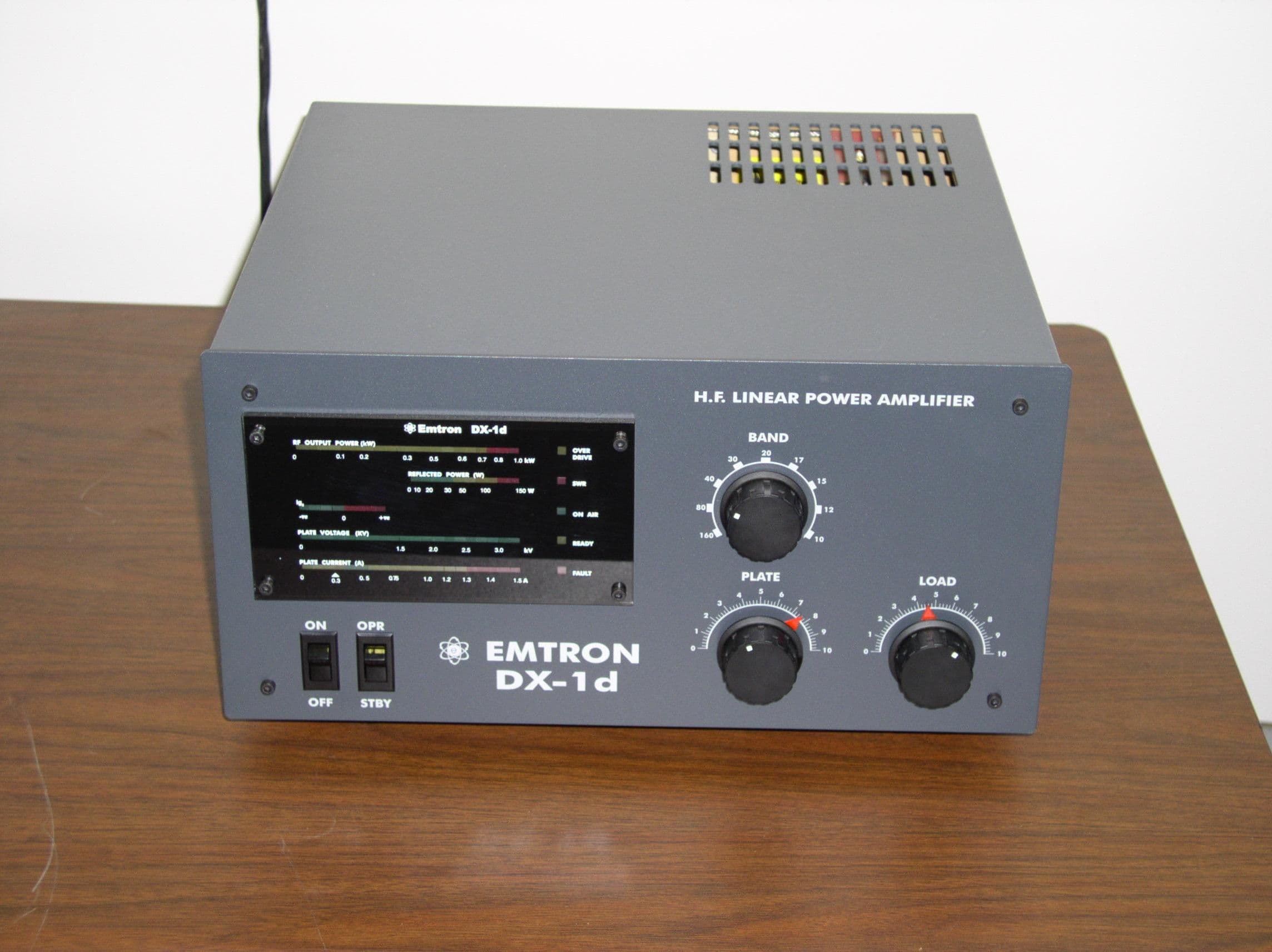
Click to zoom
Application Details
- Equipment Class
- AMP - Amplifier
- Date of Grant
- Jun 29, 2003
- Application Purpose
- Original Equipment
- Date of Application
- Jun 12, 2003
- Equipment Note
- HF Amateur
- Frequency Range
- 1.80000000 - 21.50000000
- Company
- Emtron North America
- Country
- United States
Documents & Files
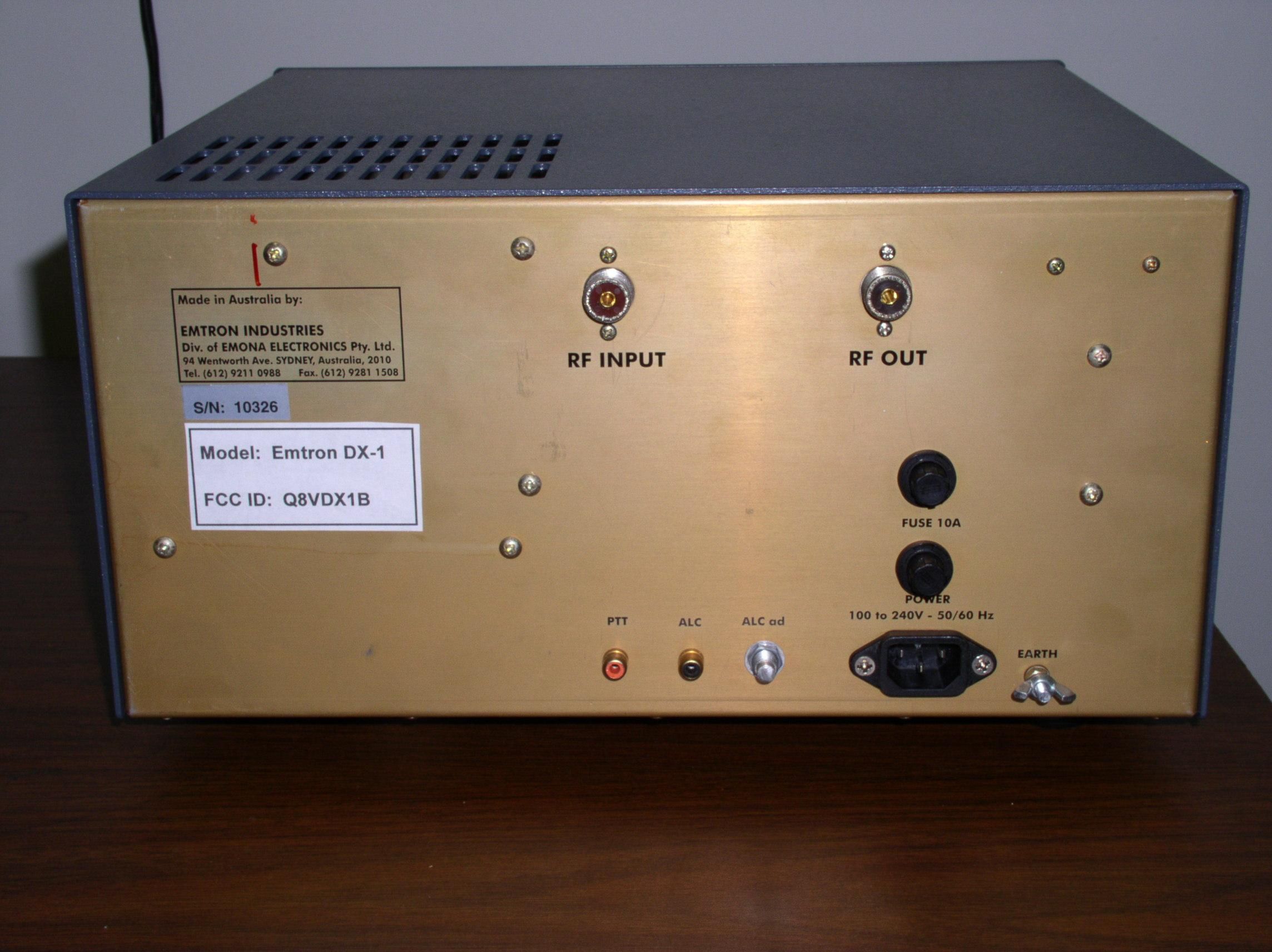
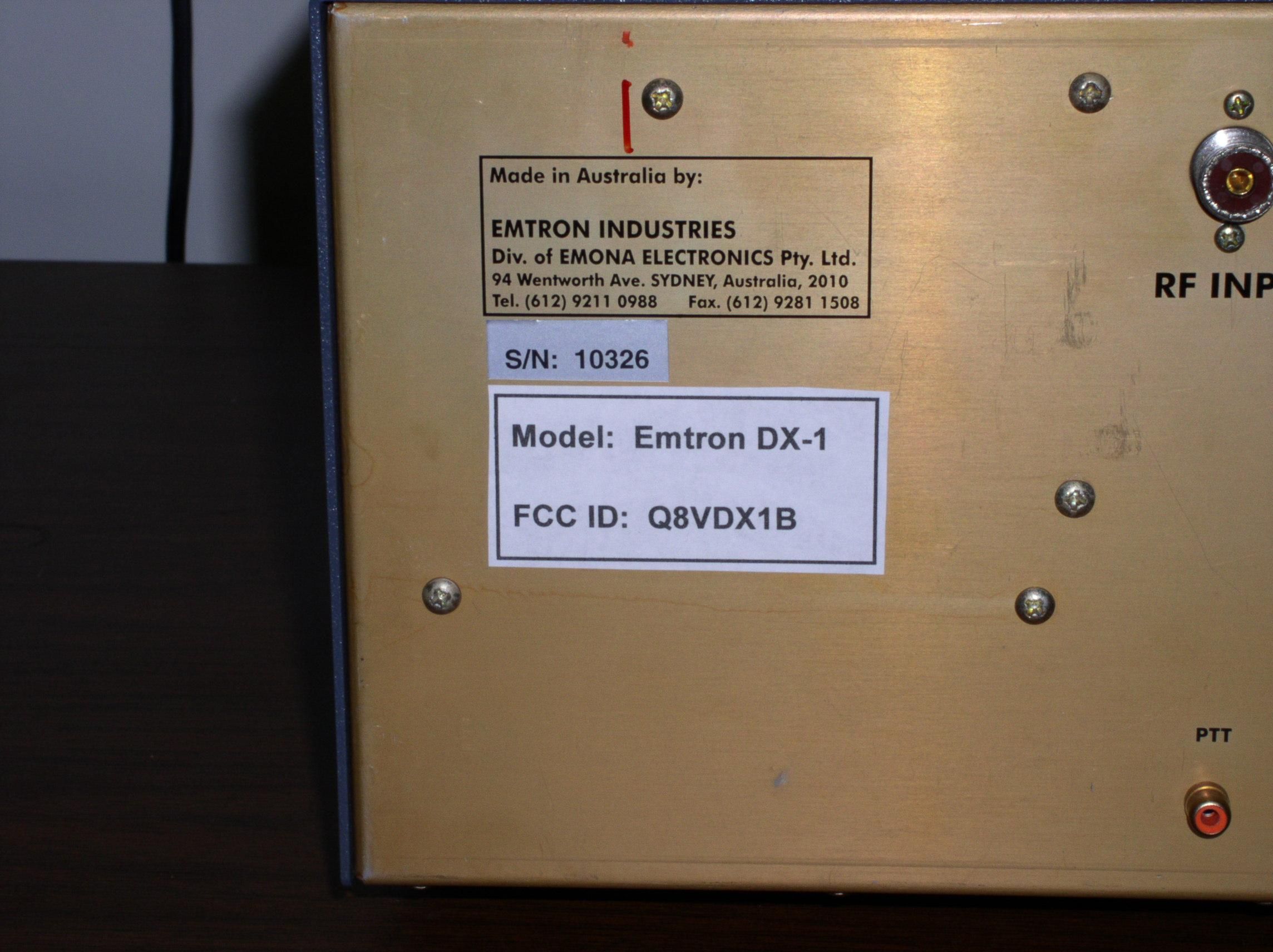
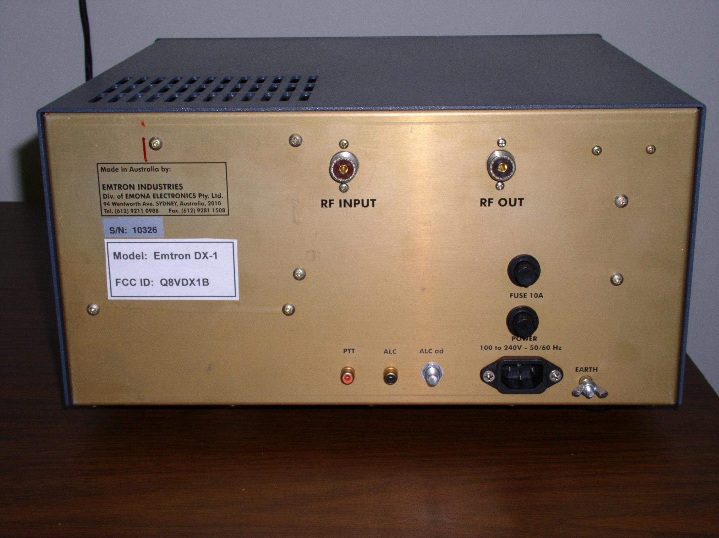
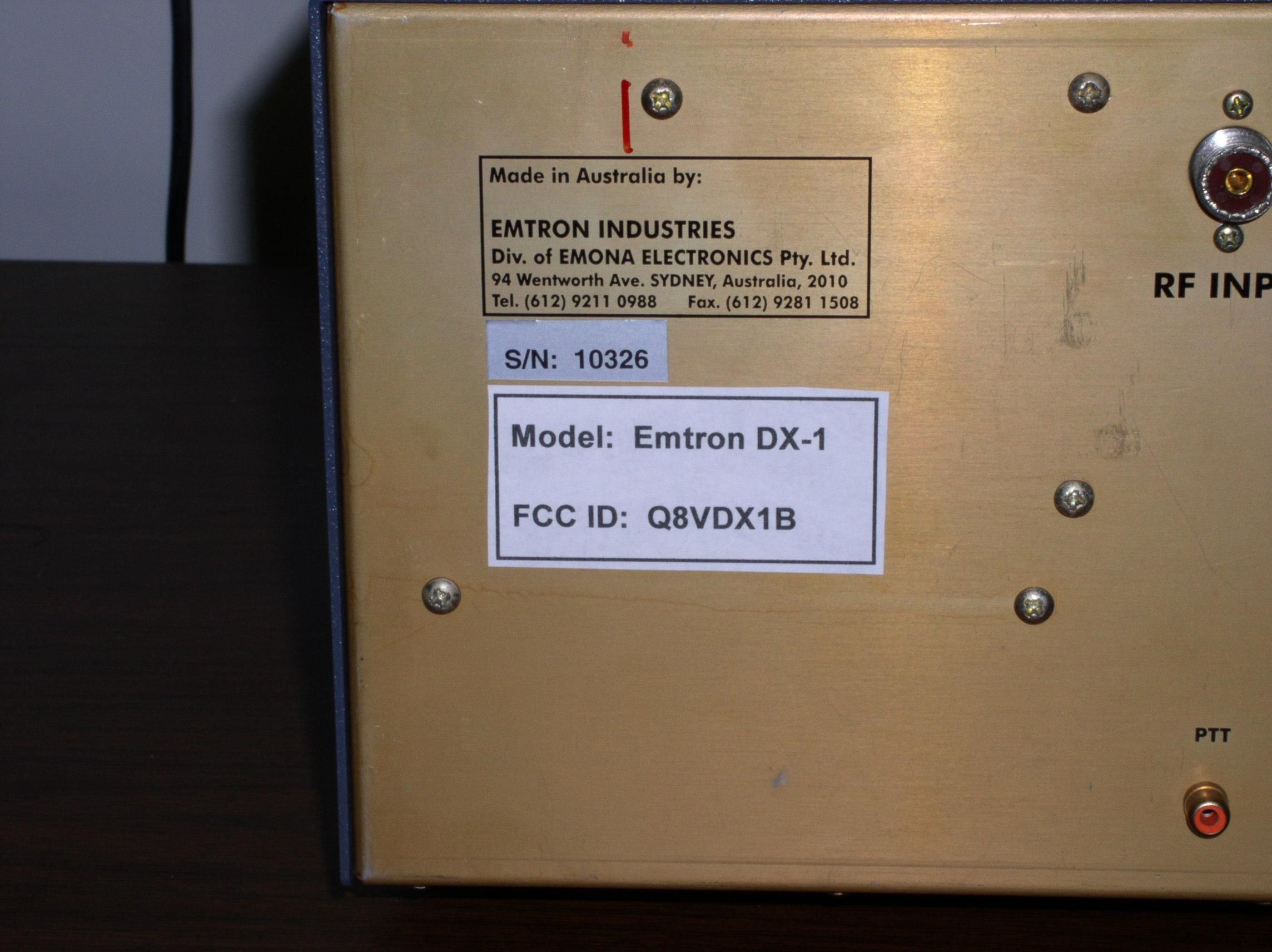
Document Text
Text extracted from the exhibit documents filed with the FCC. Open a document above to read the original.
Users Manual
OPERATING MANUAL EMTRON DX-1d HF LINEAR AMPLIFIER April 2003 Emtron DIVISION OF EMONA ELECTRONICS PTY. LTD. 92-94 Wentworth Avenue, Sydney 2010, Australia Tel. +612 92110988 Fax +612 92811508 www.emtron.com.au 2 DX-1d, Serial No............ INITIAL SETTINGS FOR PLATE AND LOAD CAPACITORS TEST FREQUENCY BAND FACTORY SETTINGS 50 OHM LOAD USER SETTING ANTENNA PLATE LOAD PLATE LOAD 28.600 MHz 10m 24.900 MHz 12m 21.200 MHz 15m 18.100 MHz 17m 14.200 MHz 20m 7.070 MHz 40m 3.600 MHz 80m 1.800MHz 160m 1.850 MHz 160m 1.900 MHz 160m TABLE 1 3 TABLE OF CONTENTS 1 GENERAL DESCRIPTION.........................................................................................................................................................5 1.1 DX-1D – INTERNAL VIEW........................................................................................................................................................6 2 TECHNICAL SPECIFICATIONS ..............................................................................................................................................7 3 UNPACKING .................................................................................................................................................................................8 3.1 OPENING THE CARTON..............................................................................................................................................................8 3.2 OPENING THE DX-1D COVER....................................................................................................................................................8 3.3 REMOVING THE PACKING BLOCK..............................................................................................................................................8 4 INSTALLATION ENVIRONMENT...........................................................................................................................................9 4.1 REQUIRED ENVIRONMENT........................................................................................................................................................9 4.2 POWER REQUIREMENTS............................................................................................................................................................9 5 REAR PANEL................................................................................................................................................................................9 5.1 POWER / EARTH CONNECTIONS................................................................................................................................................9 5.2 RF CONNECTIONS.....................................................................................................................................................................9 5.3 TRANSCEIVER CONTROL...........................................................................................................................................................9 6 FRONT PANEL ...........................................................................................................................................................................10 6.1 CONTROLS..............................................................................................................................................................................10 6.2 DISPLAYS................................................................................................................................................................................10 7 ELECTRICAL CONNECTIONS ..............................................................................................................................................12 7.1 CONNECTIONS TO TRANSCEIVER / EXCITER...........................................................................................................................12 7.2 EARTH AND MAINS CONNECTIONS..........................................................................................................................................12 7.3 THE POWER CABLE (EXPORT VERSION) ..................................................................................................................................12 7.4 OPERATION AT 230V, 220V, 200V, 100V AND 120V (EXPORT VERSION).............................................................................12 8 DX-1D DESCRIPTION...............................................................................................................................................................14 8.1 RF SECTION............................................................................................................................................................................14 8.2 MAINS TRANSFORMER............................................................................................................................................................14 8.3 H. V. POWER SUPPLY.............................................................................................................................................................14 8.4 SOFT START MODULE..............................................................................................................................................................14 8.5 SENSOR MODULE....................................................................................................................................................................14 8.6 ANTENNA RELAY / QSK MODULE..........................................................................................................................................14 8.7 DISPLAY BOARD.....................................................................................................................................................................15 8.8 CONTROLLER BOARD...........................................................................…
Text truncated - open the document above for the full version.
Users Manual
OPERATING MANUAL EMTRON DX-1d HF LINEAR AMPLIFIER April 2003 Emtron DIVISION OF EMONA ELECTRONICS PTY. LTD. 92-94 Wentworth Avenue, Sydney 2010, Australia Tel. +612 92110988 Fax +612 92811508 www.emtron.com.au 2 DX-1d, Serial No............ INITIAL SETTINGS FOR PLATE AND LOAD CAPACITORS TEST FREQUENCY BAND FACTORY SETTINGS 50 OHM LOAD USER SETTING ANTENNA PLATE LOAD PLATE LOAD 28.600 MHz 10m 24.900 MHz 12m 21.200 MHz 15m 18.100 MHz 17m 14.200 MHz 20m 7.070 MHz 40m 3.600 MHz 80m 1.800MHz 160m 1.850 MHz 160m 1.900 MHz 160m TABLE 1 3 TABLE OF CONTENTS 1 GENERAL DESCRIPTION.........................................................................................................................................................5 1.1 DX-1D – INTERNAL VIEW........................................................................................................................................................6 2 TECHNICAL SPECIFICATIONS ..............................................................................................................................................7 3 UNPACKING .................................................................................................................................................................................8 3.1 OPENING THE CARTON..............................................................................................................................................................8 3.2 OPENING THE DX-1D COVER....................................................................................................................................................8 3.3 REMOVING THE PACKING BLOCK..............................................................................................................................................8 4 INSTALLATION ENVIRONMENT...........................................................................................................................................9 4.1 REQUIRED ENVIRONMENT........................................................................................................................................................9 4.2 POWER REQUIREMENTS............................................................................................................................................................9 5 REAR PANEL................................................................................................................................................................................9 5.1 POWER / EARTH CONNECTIONS................................................................................................................................................9 5.2 RF CONNECTIONS.....................................................................................................................................................................9 5.3 TRANSCEIVER CONTROL...........................................................................................................................................................9 6 FRONT PANEL ...........................................................................................................................................................................10 6.1 CONTROLS..............................................................................................................................................................................10 6.2 DISPLAYS................................................................................................................................................................................10 7 ELECTRICAL CONNECTIONS ..............................................................................................................................................12 7.1 CONNECTIONS TO TRANSCEIVER / EXCITER...........................................................................................................................12 7.2 EARTH AND MAINS CONNECTIONS..........................................................................................................................................12 7.3 THE POWER CABLE (EXPORT VERSION) ..................................................................................................................................12 7.4 OPERATION AT 230V, 220V, 200V, 100V AND 120V (EXPORT VERSION).............................................................................12 8 DX-1D DESCRIPTION...............................................................................................................................................................14 8.1 RF SECTION............................................................................................................................................................................14 8.2 MAINS TRANSFORMER............................................................................................................................................................14 8.3 H. V. POWER SUPPLY.............................................................................................................................................................14 8.4 SOFT START MODULE..............................................................................................................................................................14 8.5 SENSOR MODULE....................................................................................................................................................................14 8.6 ANTENNA RELAY / QSK MODULE..........................................................................................................................................14 8.7 DISPLAY BOARD.....................................................................................................................................................................15 8.8 CONTROLLER BOARD...........................................................................…
Text truncated - open the document above for the full version.
Operational Description
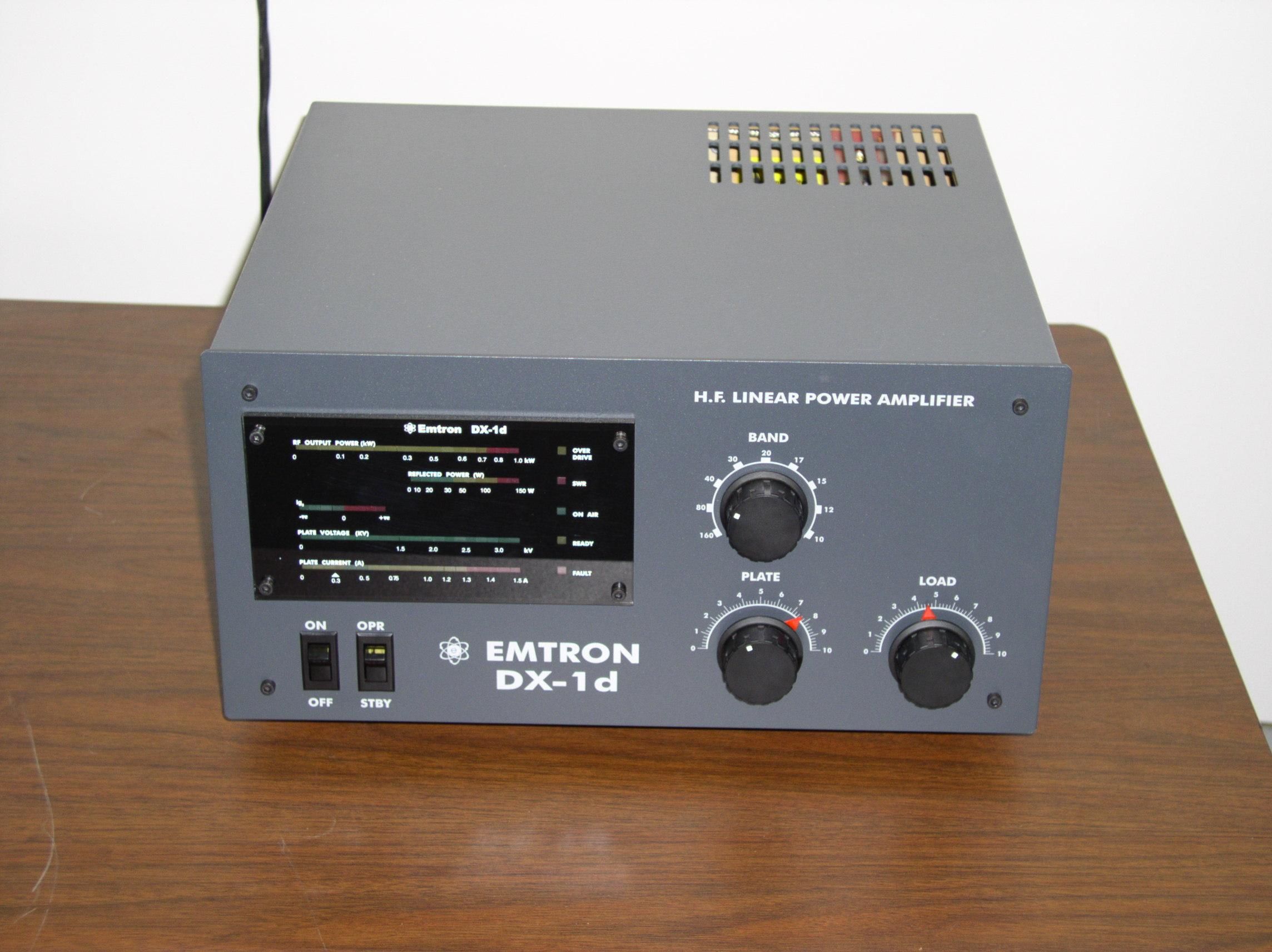
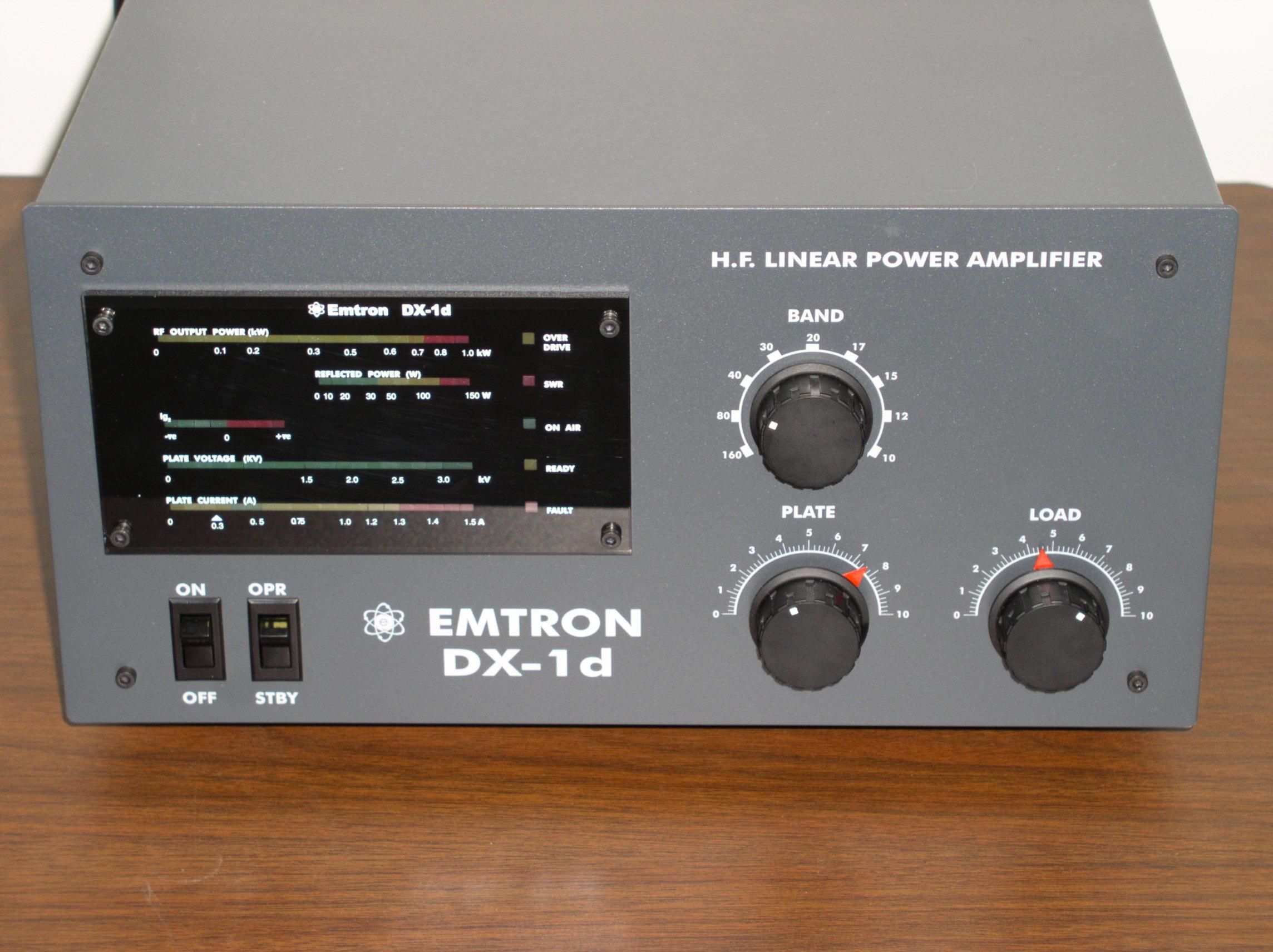
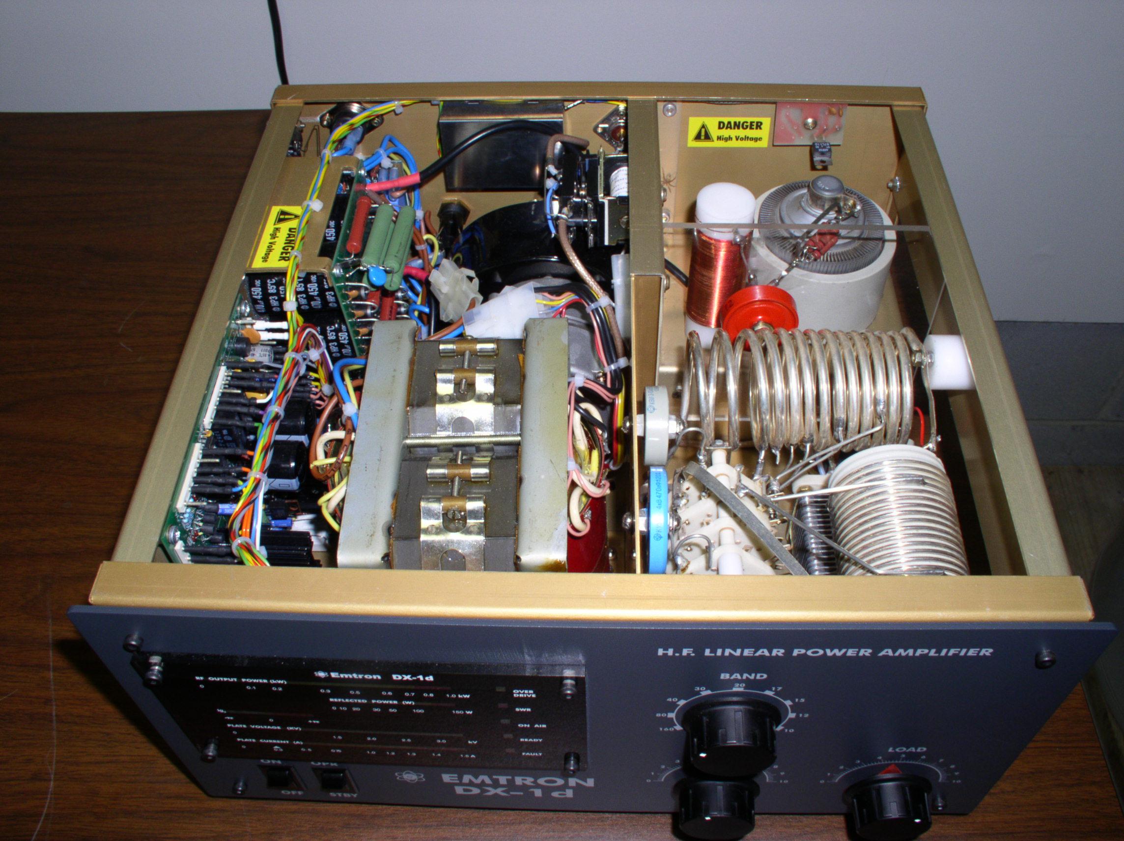
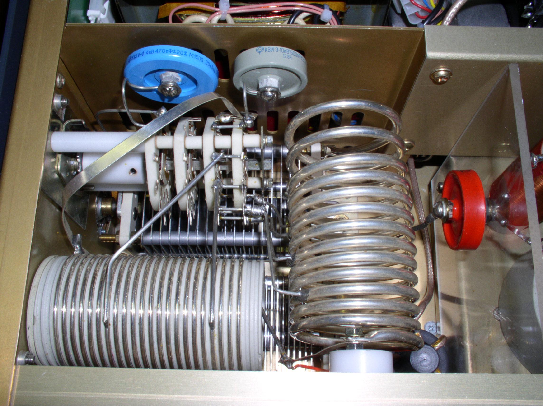
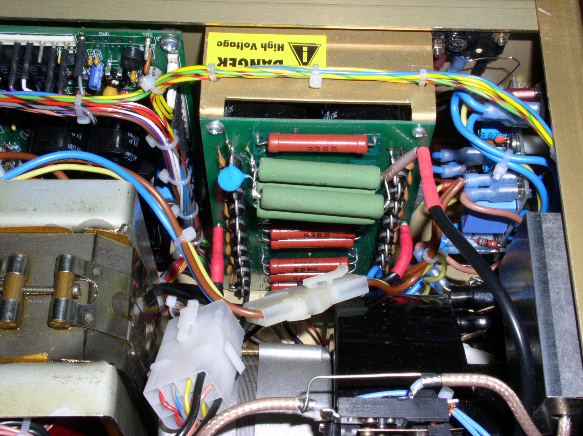
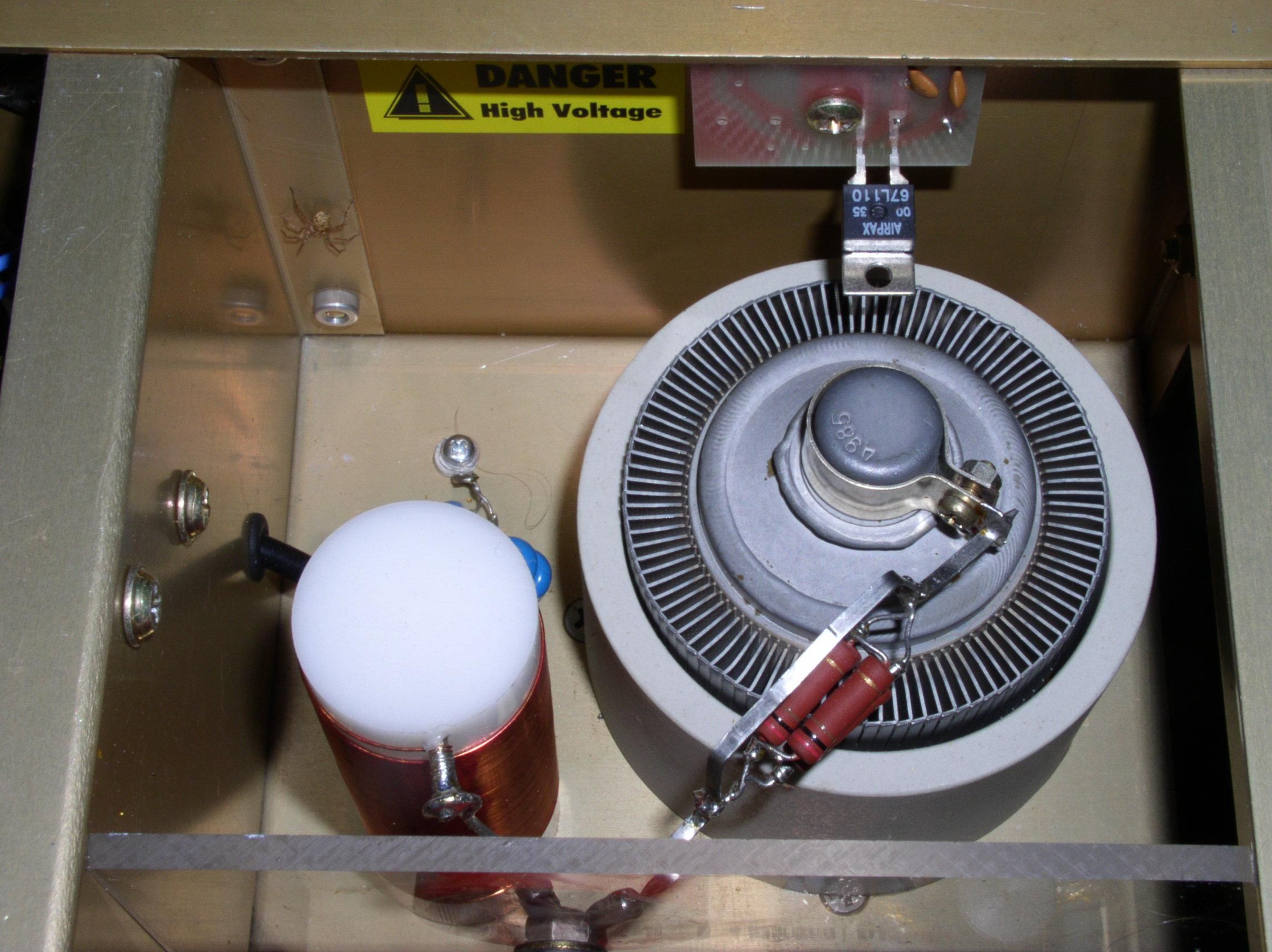
1 DX-1d DESCRIPTION 1.1 RF Section The RF section occupies the right hand side of the DX-1d (looking from the top - front). See picture in 1.1. RF Switch and tuned circuits At the front of the amplifier are two variable capacitors, for plate and load tuning. A 9- position ceramic switch is employed for the 9 operating bands. Next to the switch is the 40 to 160 metre tank coil. The silver plated, large diameter copper tube is the 10 to 30 metre tank coil. RF Sub-chassis The 4CX800A tube is positioned on a separate RF sub-chassis. All the connections to the tube, except for the plate, are under this sub-chassis. A 9-way heavy duty connector is used for the outside connections. The fan blows air into this sub-chassis, which is forced out through the ventilation fins of the tube. The air temperature is sensed by a sensor placed above the tube. The sensor must stay in a position close to horizontal. Make sure you are not pushing it down, too close to the tube, as high voltage exists between them. The plate is connected to the RF network and to the choke supplying the 2100VDC voltage to the plate of the 4CX800A tube. 1.2 Mains transformer The transformer is the heart of the amplifier, a high performance type, designed to reduce the size and weight. It is built with a generous reserve of power, handling easily the DX- 1d requirements in continuous operation. The primary can be wired for 120V, 200VAC, 220VAC, 230VAC or 240VAC operation. See Figure 2. There are several secondary windings, as follows: • Filament supply • Low voltage supply to the controller board • QSK module supply • Bias supply • Screen grid supply • High voltage supply 1.3 H. V. Power Supply A full wave bridge rectifier and filter converts the high voltage AC into high voltage DC with a huge reserve capacity of 58 microfarads. 1.4 Soft start module At power up, the mains power is gradually applied to the transformer by the soft start module. The power is gradually applied over a time of about 5 seconds, avoiding the high inrush current typical for such big loads. 1.5 Sensor module A small metal box positioned at the output of the DX-1d. It detects the forward and reverse power, for measurement and display. 1.6 Antenna relay / QSK module In the standard DX-1d, the antenna relay is controlled by the transceiver, via the control board. It switches the antenna between the transceiver, during reception, and amplifier, during transmission. It is also used to bypass the RF from the transceiver, directly into the antenna, when the amplifier is in standby mode, or during special conditions like overdrive, bad SWR or other error conditions. When the QSK option is installed, this is a module with two very fast, high power vacuum relays, and the control circuitry. The purpose of QSK is to allow very fast switching between transmit and receive, during digital communications. See Annex 1 showing oscilloscope displays of fast switching times and contact bounce-free operation of the QSK module. 1.7 Display board This board has a number of inputs where various voltages are connected. The board converts these voltages into a "moving LED" type of display. Two of these displays have flashing light indication (Ig2 and plate current). 1.8 Controller board The brain of the amplifier is the Controller Board. The following circuitry is part of this board: • Bias voltage regulator, also incorporating a sensitive grid current detector for overdrive detection . Adjustable pre-bias, removes the distortion at the beginning of the word, when EBS is activated. • Screen voltage regulator, with adjustable voltage and adjustable current limiting, for tube protection. • Overdrive protection and timer - based on detecting grid current, it initially gives visual warning and, at higher level of overdrive, it cuts off the amplifier for 2 seconds. It ensures a clean signal, making it virtually impossible to overdrive the DX-1d • SWR detector and timer - switches the amplifier to bypass mode for about 3 seconds when high SWR is detected. Adjustable SWR level. Factory adjusted to about 2.6: 1 • EBS - the Electronic Bias Switch - senses the presence of RF input power and turns on the bias to start transmission. Factory adjusted for about 0.5W. When the input power exceeds this limit, the plate current starts flowing. When there is no speech, even for a very short time, the tube dissipation is cut to a low value, as set by the pre-bias adjustment. • Interlocking, timer for filament warm-up • Relay control: ready relay, SWR relay, over-drive relay, antenna relay • QSK switching control • Display control: Ig2 measurement and display, SWR cut-off display, overdrive warning display, READY display, FAULT display • Logic circuitry, low voltage supply to the various electronic circuits
Operational Description
1 DX-1d DESCRIPTION 1.1 RF Section The RF section occupies the right hand side of the DX-1d (looking from the top - front). See picture in 1.1. RF Switch and tuned circuits At the front of the amplifier are two variable capacitors, for plate and load tuning. A 9- position ceramic switch is employed for the 9 operating bands. Next to the switch is the 40 to 160 metre tank coil. The silver plated, large diameter copper tube is the 10 to 30 metre tank coil. RF Sub-chassis The 4CX800A tube is positioned on a separate RF sub-chassis. All the connections to the tube, except for the plate, are under this sub-chassis. A 9-way heavy duty connector is used for the outside connections. The fan blows air into this sub-chassis, which is forced out through the ventilation fins of the tube. The air temperature is sensed by a sensor placed above the tube. The sensor must stay in a position close to horizontal. Make sure you are not pushing it down, too close to the tube, as high voltage exists between them. The plate is connected to the RF network and to the choke supplying the 2100VDC voltage to the plate of the 4CX800A tube. 1.2 Mains transformer The transformer is the heart of the amplifier, a high performance type, designed to reduce the size and weight. It is built with a generous reserve of power, handling easily the DX- 1d requirements in continuous operation. The primary can be wired for 120V, 200VAC, 220VAC, 230VAC or 240VAC operation. See Figure 2. There are several secondary windings, as follows: • Filament supply • Low voltage supply to the controller board • QSK module supply • Bias supply • Screen grid supply • High voltage supply 1.3 H. V. Power Supply A full wave bridge rectifier and filter converts the high voltage AC into high voltage DC with a huge reserve capacity of 58 microfarads. 1.4 Soft start module At power up, the mains power is gradually applied to the transformer by the soft start module. The power is gradually applied over a time of about 5 seconds, avoiding the high inrush current typical for such big loads. 1.5 Sensor module A small metal box positioned at the output of the DX-1d. It detects the forward and reverse power, for measurement and display. 1.6 Antenna relay / QSK module In the standard DX-1d, the antenna relay is controlled by the transceiver, via the control board. It switches the antenna between the transceiver, during reception, and amplifier, during transmission. It is also used to bypass the RF from the transceiver, directly into the antenna, when the amplifier is in standby mode, or during special conditions like overdrive, bad SWR or other error conditions. When the QSK option is installed, this is a module with two very fast, high power vacuum relays, and the control circuitry. The purpose of QSK is to allow very fast switching between transmit and receive, during digital communications. See Annex 1 showing oscilloscope displays of fast switching times and contact bounce-free operation of the QSK module. 1.7 Display board This board has a number of inputs where various voltages are connected. The board converts these voltages into a "moving LED" type of display. Two of these displays have flashing light indication (Ig2 and plate current). 1.8 Controller board The brain of the amplifier is the Controller Board. The following circuitry is part of this board: • Bias voltage regulator, also incorporating a sensitive grid current detector for overdrive detection . Adjustable pre-bias, removes the distortion at the beginning of the word, when EBS is activated. • Screen voltage regulator, with adjustable voltage and adjustable current limiting, for tube protection. • Overdrive protection and timer - based on detecting grid current, it initially gives visual warning and, at higher level of overdrive, it cuts off the amplifier for 2 seconds. It ensures a clean signal, making it virtually impossible to overdrive the DX-1d • SWR detector and timer - switches the amplifier to bypass mode for about 3 seconds when high SWR is detected. Adjustable SWR level. Factory adjusted to about 2.6: 1 • EBS - the Electronic Bias Switch - senses the presence of RF input power and turns on the bias to start transmission. Factory adjusted for about 0.5W. When the input power exceeds this limit, the plate current starts flowing. When there is no speech, even for a very short time, the tube dissipation is cut to a low value, as set by the pre-bias adjustment. • Interlocking, timer for filament warm-up • Relay control: ready relay, SWR relay, over-drive relay, antenna relay • QSK switching control • Display control: Ig2 measurement and display, SWR cut-off display, overdrive warning display, READY display, FAULT display • Logic circuitry, low voltage supply to the various electronic circuits
Operational Description
EMTRON DX-1 - CIRCUIT DESCRIPTIONS The input RF stage. The input circuit of the Emtron DX-1d linear amplifier utilises a 50 ohm passive “L Pad” network with SWR compensation. This network consists of two non-inductive power resistors, an inductor and a capacitor. The input signal is coupled to the control grid via a coaxial cable, passive input network, 1500pF silver mica capacitor and a 10 ohm resistor. A portion of the input signal is also being rectified in a voltage doubling circuit C13, D1, D2 and C7 and the generated –ve DC output signal is controlling the Electronic Bias Switch (EBS) on the control board. The Control Board 1. Screen supply Refer to the top left part of the circuit diagram. Nominally 300 Vac is applied to the bridge BR1, creating about 420 Vdc on C1 and C2. When the relay RL2 (OPR/STBY) is activated, this voltage is applied to the series pass transistor Q2. Otherwise, when the amplifier is not READY, or it is in STANDBY, there is no screen voltage. The voltage is regulated by U1 via the optocoupler U8 and op-amp Q1. U1A will maintain the voltage on the POT2 wiper equal to the reference given by D10. POT2 is the screen voltage adjustment. R7 and Q3 provide the current limiting. The current limit is adjusted by POT1. This circuit is intended to limit the screen current during the normal tube operation, preventing it from going over 40 mA. In short circuit, Q2 dissipation could reach 16W. To avoid Q2 overheating in case of a permanent short circuit, Q18 will turn off the screen voltage, as soon as a very low output voltage is detected. The series pass regulator can only source, but not sink current. When a negative screen current is generated by the tetrode, R8 and R78 will sink a certain amount of current, creating a negative voltage drop on R10. This will turn on Q4, which will proportionally drive Q5. This will create sufficient current in R12, R13 to load down the screen voltage and maintain the voltage regulation. At all other times Q5 is off and it does not load the screen regulator unnecessarily. The optocouplers U9 and U10 transmit the screen current information to the display board, for negative and positive currents, respectively. R18 and the diodes D2,D3, D27, D28 create a shunt. They pass most of the screen current, with only a fraction going into R16 or R17. The regulated 350 Vdc screen supply is being applied to the screen of the GU74B (4CX800) tube via the Flash-over protection circuit. The purpose of this protection circuit is to dissipate the energy stored in the HV power supply when released to the screen, in case of a tube flash-over and consequently protecting the tube as well as the 350Vdc regulated screen power supply on the control board. 2. Bias circuit This is at the bottom left side of the circuit diagram. The bridge BR2 gets 100 Vac, charging C9 to about (- 120) Vdc. Since this circuit needs to deliver only a very small current, a simple shunt regulator is used. R35 and R40 form a voltage divider, with Q7 conducting just enough current to maintain the bias voltage constant. The voltage reference is D11, which keeps the base of Q16 at - 5.6V. POT3 is the bias adjustment. For Q7 to conduct, 2 conditions are required: - The optoclupler U6 must be activated by the PTT contact. - Q9 must be off, either due to the EBS link in the lower position, or a negative voltage present on the RFIN pin. 3. Electronic Bias Switch Q9 is off only when either the EBS is disabled by the link on SW1 placed in the upper position, or (with the link in the lower position), there is a negative voltage at point RFIN, which turns Q8 ON and Q9 OFF. POT4 is the sensitivity adjustment for the EBS circuit. 4. Pre-Bias The pre-bias circuit is made up of Q22 and Q23. When the amplifier is keyed but there is no audio signal to turn on the bias, the negative voltage is prevented to completely cut off the tube, by maintaining a small plate current, adjusted by POT7. With PTT off, Q7 and Q23 are off and there is no plate current. With PTT on, but no input RF drive, Q7 is off, while Q23 is on just enough to reduce the bias voltage (in absolute value), to the level required by the pre-bias current previously adjusted. With PTT on and RF drive present, there is normal operating plate current. With PTT on and the link in the lower position there is standing plate current. 5. 12Vdc supply BR3 rectifies the 10Vac and charges C5 to 12 - 14 V. At power up, this voltage is initially applied only to the timer U5, the +5V regulator U13, the timers U3, U4 and the operational amplifiers U1 and U2. 6. +5Vdc supply All the time while the power is on, U13 supplies +5V regulated to the display board. 7. Warm-up timer The timer IC 555 gives about 2 minutes of warm up time when the power is turned on. This is the time required by C7 and C23 to charge to about 3.33 V. When the time is up, pin 3 of U5 goes low, activating RL 1 (the READY relay) via the PCB pins X7.6 and X7.5, connected to the 110ºC sensor (normally closed), located above the tube. At this moment, RL1 applies 12V to RL2 and R21, turning on the READY LED. 8. Operate With the STBY (front panel) switch open, RL2 is not powered. When the switch is closed, RL2 is energized. This causes the screen voltage to turn on and 12V to be applied to the antenna relay RL Y1 and to other circuits. 9. Antenna relay I QSK activation While in OPERATE mode, closing PTT1 point (X3.5 - bottom right hand corner of schematic) to ground will cause either the antenna relay, or the QSK module to energize. In normal operation RL4 is energized (See below. - Also note: there is no RL3). The joint point of Q8 and Q9 is grounded and so is RL Y2 (X4.5) and QSK1 (X4.2). The pin QSK2 (X3.3) supplies the QSK module with about 30 Vdc, via BR4. PTT on also pulls low Q13 collector and X5.6 (OD/TX), causing the "ON AIR" LED connected to TXON (X5.5) to turn on. 10. Grid current detector and overdrive protection Q6 is a current mirror circuit. Any grid current flowing in its em…
Text truncated - open the document above for the full version.
Parts List/Tune Up Info
ÐÏ à¡± á > þÿ E þÿÿÿ þÿÿÿ D ÿÿÿÿÿÿÿÿÿÿÿÿÿÿÿÿÿÿÿÿÿÿÿÿÿ ÿÿÿÿÿÿÿÿÿÿÿÿÿÿÿÿÿÿÿÿÿÿÿÿÿÿÿÿÿÿÿÿÿÿÿÿÿÿÿÿÿÿÿÿÿÿÿÿÿÿÿÿÿÿÿÿÿÿÿÿÿÿÿÿÿÿÿÿÿÿÿÿÿÿÿÿÿÿÿÿ ÿÿÿÿÿÿÿÿÿÿÿÿÿÿÿÿÿÿÿÿÿÿÿÿÿÿÿÿÿÿÿÿÿÿÿÿÿÿÿÿÿÿÿÿÿÿÿÿÿÿÿÿÿÿÿÿÿÿÿÿÿÿÿÿÿÿÿÿÿÿÿÿÿÿÿÿÿÿÿÿ ÿÿÿÿÿÿÿÿÿÿÿÿÿÿÿÿÿÿÿÿÿÿÿÿÿÿÿÿÿÿÿÿÿÿÿÿÿÿÿÿÿÿÿÿÿÿÿÿÿÿÿÿÿÿÿÿÿÿÿÿÿÿÿÿÿÿÿÿÿÿÿÿÿÿÿÿÿÿÿÿ ÿÿÿÿÿÿÿÿÿÿÿÿÿÿÿÿÿÿÿÿÿÿÿÿÿÿÿÿÿÿÿÿÿÿÿÿÿÿÿÿÿÿÿÿÿÿÿÿÿÿÿÿÿÿÿÿÿÿÿÿÿÿÿÿÿÿÿÿÿÿÿÿÿÿÿÿÿÿÿÿ ÿÿÿÿÿÿÿÿÿÿÿÿÿÿÿÿÿÿÿÿÿÿÿÿÿÿÿÿÿÿÿÿÿÿÿÿÿÿÿÿÿÿÿÿÿÿÿÿÿÿÿÿÿÿÿÿÿÿÿÿÿÿÿÿÿÿÿÿÿÿÿÿÿÿÿÿÿÿÿÿ ÿÿÿÿÿÿÿ F Í É€ á ° Á â \ p Dr. Vincent D. Cammarata B ° a À = œ ̄ ¼ = Ð á \+¾#8 X @ " · Ú 1 È ÿ A r i a l 1 È ÿ A r i a l 1 È ÿ A r i a l 1 È ÿ A r i a l 1 È ÿ ¼ A r i a l 1 ð ÿ ¼ A r i a l 1 È ¼ A r i a l 1 È ÿ A r i a l 1 Ü ÿ ¼ A r i a l - "$"#,##0_);\("$"#,##0\)- ! "$"#,##0_);[Red]\("$"#,##0\)- " " $"#,##0.00_);\("$"#,##0.00\)- ' " "$"#,##0.00_);[Red]\("$"#,##0.00\)- 7 * 2 _("$"* #,##0_);_("$"* \(#,##0\);_("$"* "-"_);_(@_)- . ) ) _(* #,##0_);_(* \(#,##0\);_(* "-"_);_(@_)- ? , : _("$"* #,##0.00_);_("$"* \(#,##0.00\);_("$"* "-"??_);_(@_)- 6 + 1 _(* #,##0.00_);_(* \(#,##0.00\);_(* "- "??_);_(@_)- ¤ "$"#,##0;\-"$"#,##0- ¥ "$"#,##0;[Red]\- "$"#,##0- - ¦ "$"#,##0.00;\-"$"#,##0.00- # § - "$"#,##0.00;[Red]\- "$"#,##0.00- 5 ̈ 0 _-"$"* #,##0_-;\-"$"* #,##0_-;_-"$"* "-"_-;_-@_-- , © ' _-* #,##0_-;\-* #,##0_-;_-* "-"_-;_-@_-- = ª 8 _-"$"* #,##0.00_-;\-"$"* #,##0.00_- ;_-"$"* "-"??_-;_-@_-- 4 « / _-* #,##0.00_-;\-* #,##0.00_-;_-* "-"??_-;_-@_- à õÿ À à õÿ ô À à õÿ ô À à õÿ ô À à õÿ ô À à õÿ ô À à õÿ ô À à õÿ ô À à õÿ ô À à õÿ ô À à õÿ ô À à õÿ ô À à õÿ ô À à õÿ ô À à õÿ ô À à À à « õÿ ø À à © õÿ ø À à ª õÿ ø À à ̈ õÿ ø À à õÿ ø À à " 8 @ @ À à @ @ À à À à " 8 @ @ À à ( @ @ À à # 0 @ @ À à # 8 @ @ À à # 8 @ @ À…
Text truncated - open the document above for the full version.
Contact Information
Applicant
Vincent D Cammarata(President/CEO)
Technical Contact
Emtron North AmericaVincent D Cammarata
[email protected]804.779.0763
6531 Boundary Run Drive · Mechanicsville, Virginia · United States
Non-Technical Contact
Emtron North AmericaVincent D Cammarata
[email protected]804.779.0763
Technical Specifications
| # | Rule Parts | Frequency Range | Power Output | Emission |
|---|---|---|---|---|
| 1 | 97 | 1.8 MHz - 21.5 MHz | 750 W | XXX |