Q99L1900CDMA20R20W RF REPEATER SYSTEM
YURASYS CO., LTD.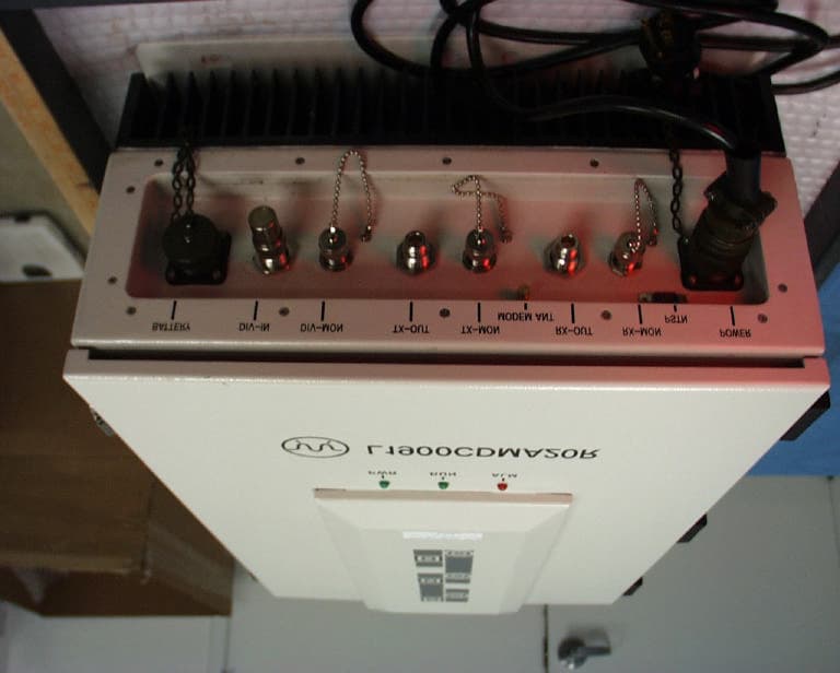
Click to zoom
Application Details
- Equipment Class
- AMP - Amplifier
- Date of Grant
- Jul 28, 2003
- Application Purpose
- Original Equipment
- Date of Application
- Jul 28, 2003
- Equipment Note
- 20W RF REPEATER SYSTEM
- Frequency Range
- 1850.00000000 - 1910.00000000
- Company
- YURASYS CO., LTD.
- Country
- South Korea
Documents & Files
Document Text
Text extracted from the exhibit documents filed with the FCC. Open a document above to read the original.
Cover Letter(s)
DATE: June 26, 2003 Federal Communications Commission Equipment Authorization branch 7435 Oakland Mills Road Columbia, MD 21046 In re: Request for Confidentiality Gentlemen: In accordance with 0.459 of CFR 47, YURASYS CO., LTD. hereby requests confidentiality of Schematics, Block Diagrams, Parts List, and Theory of Operation for the subject application. These documents contain detailed system and equipment description and related information about the product that YURASYS CO., LTD. considers to be proprietary, confidential, and a custom design and, otherwise, would not release to the general public. Since this design is a basis from which future technological products will evolve, YURASYS CO., LTD. considers that this information would be of benefit to its competitors, and that disclosure of the information in these documents would give competitors an unfair advantage in the market. Sincerely In Kim, Marketing Manager YURASYS CO.,LTD. 3f, Shinho Building, 906-16 Daechi-Dong, Gangnam-Gu, Seoul Korea
Cover Letter(s)
Hi Steve, Please see answers below. Thanks, Thu -----Original Message----- From: Steve Cheng Sent: Thursday, July 24, 2003 9:12 PM To: Thu Chan; CLIENT ADVOCATES Cc: Mike Kuo Subject: RE: AN03T3012 URUSYS REPEATER RT for project: AN03T3012 URUSYS REPEATER Notice_content Question #1: In page 2 of users manual it indicated, “The information contained in this documents is ‘Confidential’. But confidentiality request letter does not request this item. And in general, FCC’s guideline is “Users manual shall be public information and shall be available to general public. Please remove sensitive info from the users manual if necessary. [Thu Chan] _ The users manual was revised to remove confidential information. Attached please find the revised manual. Question #2: Page 35 show that power is software configurable; please explain how manufacture can prevent the end user to configure the power from exceed the limit? [Thu Chan] _ The device will be sold only to the firms who can provide professional installation. The installation personnels have the knowledge to keep the power from exceeding the limit. Question #3: page 5 “7. APPLICABLE RULES AND BRIEF TEST RESULT”, there was no brief result. Please clarify. [Thu Chan] _ Please see attachments for revised report. Question #4: in section 8.2. “ MODULATION CHARACTERISTICS (NOT APPLICABLE TO THIS REPEATER, THE EUT DOESN’T HAVE A FREQUENCY TRANSLATOR OR MODULATOR INSIDE OF EUT. THE EUT IS AN AMPLIFIER TYPE REPEATER.). The description does not seem to match the technical description in theatrical operation. In the Theory of Operation this device does convert the input signal to IF and than convert back after filtering and amplification. Please clarify. [Thu Chan] _Although EUT is not a pure AMP type repeater, but EUT does only frequency translation and does not demodulate the base band signal in whole process. Due to the frequency translation, we have included the frequency stability test data. Please also see attachments for revised report. Question #5: Two equipment listed are out of calibration in page 10 as listed below Spectrum Analyzer HP 8593EM 6/20/02 Signal Generator Rohde & Schwarz SMIQ 03 5/25/02 Please explain. [Thu Chan] _ It is a typo, please see attachments for revised report. Question #6: Why band D, E, F did only one pair of 2 signals IM test instead of 2 pair of 2 signals IM test as required in FCC IM test guideline? [Thu Chan] _ Since D, E, and F have only 5M bands and the signal bandwidth is around 1.5M. So the second test will virtually repeat the same test as first set. Question #7: IM plots not matching the table please re-arrange the plots. [Thu Chan] _ Please see attachments for revised plots & report. The items indicated above must be submitted before processing can continue on the above referenced application. Failure to provide the requested information within 60 days of the original e-mail date may result in application dismissal and forfeiture of the filing fee. Also, please note that partial responses increase processing time and should not be submitted. Any questions about the content of this correspondence should be directed to the e-mail address listed below the name of the sender. Best Regards Steve Cheng Compliance Certification Services 561F Monterey Road Morgan Hill, CA 95037 Tel:(408)463-0885 x:119 Fax:(408)463-0888 [email protected] http:\\www.ccsemc.com
ID Label/Location Info
PROPOSED FCC ID LABEL AND LOCATION YURASYS CO., LTD. This device complies with Part 24 of the FCC Rules. FCC ID: Q99L1900CDMA20R FCC ID LABEL LOCATION
Parts List/Tune Up Info
Date 2003/06/25 Doc No. YRT-030625-1 Rev No. 1.0 File Name Tune_Up.doc Page 1/1 Report by Ji-Hyo Kim Approve by Document control Manager Kong-Hoe Hur Type of Document Technical Document Title : Tune up Procedure of 20W High Power RF Repeater System YQF-041-13(Rev.0) Copyright YURASYS 2003 Tune up Procedure of 20W High Power RF Repeater System JUN / 2003 Date 2003/06/25 Doc No. YRT-030625-1 Rev No. 1.0 File Name Tune_Up.doc Page 2/2 Report by Ji-Hyo Kim Approve by Document control Manager Kong-Hoe Hur Type of Document Technical Document Title : Tune up Procedure of 20W High Power RF Repeater System YQF-041-13(Rev.0) Copyright YURASYS 2003 CONTENTS 1. Tune Up Procedure for Forward Link...................................................................3 1.1. Maximum Output Power, System Gain and Gain Control..........................3 1.1.1. Object.....................................................................................................3 1.1.2. Standard................................................................................................3 1.1.3. Instrument List.....................................................................................3 1.1.4. Calibration Procedure..........................................................................3 1.1.5. Test Configuration Diagram................................................................5 1.1.6. Test Procedure.......................................................................................5 1.2. Gain Control Test.............................................................................................7 1.2.1. Object.....................................................................................................7 1.2.2. Standard................................................................................................7 1.2.3. Instrument List.....................................................................................7 1.2.4. Test Configuration Diagram................................................................7 1.2.5. Test Procedure.......................................................................................8 2.Tune Up Procedure for Reverse Link....................................................................9 2.1. Maximum Output Power, System Gain and Gain Control..........................9 2.1.1. Object.....................................................................................................9 2.1.2. Standard................................................................................................9 2.1.3. Instrument List.....................................................................................9 2.1.4. Calibration Procedure..........................................................................9 2.1.5. Test Configuration Diagram...............................................................11 2.1.6. Test Procedure......................................................................................11 2.2. Gain Control Test...........................................................................................13 2.2.1. Object...................................................................................................13 2.2.2. Standard..............................................................................................13 2.2.3. Instrument List...................................................................................13 2.2.4. Test Configuration Diagram..............................................................13 2.2.5. Test Procedure.....................................................................................14 Date 2003/06/25 Doc No. YRT-030625-1 Rev No. 1.0 File Name Tune_Up.doc Page 3/3 Report by Ji-Hyo Kim Approve by Document control Manager Kong-Hoe Hur Type of Document Technical Document Title : Tune up Procedure of 20W High Power RF Repeater System YQF-041-13(Rev.0) Copyright YURASYS 2003 1. Tune Up Procedure for Forward Link 1.1. Maximum Output Power, System Gain and Gain Control 1.1.1. Object The characteristics of Maximum Output Power and System Gain shall meet the standard specification 1.1.2. Standard Input Power Output Power Error -52dBm/1FA 43dBm/1FA -2dB ~ +2dB Gain Error 95 dB < 2dB 1.1.3. Instrument List 1) HP8563E Spectrum Analyzer 1 Set 2) HP4432B Digital Signal Generator 1 Set 3) Power Meter 1 set and Power sensor 1 set 4) High Power 30dB Attenuator 1 EA (Over 100W) 1 Set 5) Cable Set 6) N-type(F) to N-type(F) Connector 1 Set 1.1.4. Calibration Procedure 1) Set System as follow Figure 1. SIGNAL GENERATIOR HP4432B Spectrum Analyzer HP8563E Figure 1 Signal Generator Calibration Configuration for Forward Link 2) Set Signal Generator as below. (1) Frequency: 1932.5MHz (2) Amplitude: -10dBm (3) Mode > CDMA Formats > IS-95 (4) Multi carrier Define > Carrier: 9CH, 3 Carriers (5) Offset Frequency: -1.25MHz, +1.25MHz (6) CDMA: ON, Mult-Carrier: Off (7) Amp Offset: 0dB Date 2003/06/25 Doc No. YRT-030625-1 Rev No. 1.0 File Name Tune_Up.doc Page 4/4 Report by Ji-Hyo Kim Approve by Document control Manager Kong-Hoe Hur Type of Document Technical Document Title : Tune up Procedure of 20W High Power RF Repeater System YQF-041-13(Rev.0) Copyright YURASYS 2003 (8) Mod: On, RF: On 3) Set Spectrum Analyzer as below. (1) Center Frequency: 1932.5MHz (2) Span: 10MHz (3) RBW: 30KHz, VBW: 300Hz (4) Amplitude - ATTEN: 10dB - REF LVL: 0dBm (5) Set to Channel Power Mode (6) Channel Bandwidth > 1.25MHz 4) Set Input Cable loss offset to Signal Generator 5) Set more Offset to Signal Generator the difference between the Amplitude of Signal Generator and the Power level of Spectrum Analyzer. - Ampl > More (1 of 2) > Ampl Offset : TBD 6) Set System as follow Figure 2. 30dB Power Attenuator POWER METER HPE4413B SIGNAL GENERATIOR HP4432B Spectrum Analyzer HP8563E Figure 2 Spectrum Analyzer Calibration Configuration for Forward Link 7) Set Output cable loss offset to Spectrum Analyzer 8) Set more Offset to Spectrum Analy…
Text truncated - open the document above for the full version.
Parts List/Tune Up Info
Date 2003/06/25 Doc No. YRT-030625-1 Rev No. 1.0 File Name Tune_Up.doc Page 8/8 Report by Ji-Hyo Kim Approve by Document control Manager Kong-Hoe Hur Type of Document Technical Document Title : Tune up Procedure of 20W High Power RF Repeater System YQF-041-13(Rev.0) Copyright YURASYS 2003 1.2.5. Test Procedure 1) System as Figure 4. (Connect: Signal Generator – RX-OUT, Spectrum Analyzer – TX-OUT) 2) Execute calibration of Spectrum Analyzer as section 2.1.4. 3) Set the Forward Link of Repeater System to maximum gain (= ATT: 0dB) with Laptop or Key Pad, and HPA (FWD): On, set B3 band, ALC: Off and Temp. Comp: Off 4) Set Signal Generator as below - Frequency: 1967.5MHz - Mod: OFF - Amplitude: -52dBm - RF: ON 5) Set Spectrum Analyzer as below - Frequency: 1967.5MHz - ATTEN: 30dB - RRF LVL: +50dBm - Peak Search - MKR > Marker Delta 6) Control the Forward Link Gain by setting the ATT with 1dB Step Size with Laptop or Key Pads. (Please refer to Operating Manual) 7) Measure and record the delta value on Spectrum Analyzer based on specification. Date 2003/06/25 Doc No. YRT-030625-1 Rev No. 1.0 File Name Tune_Up.doc Page 9/9 Report by Ji-Hyo Kim Approve by Document control Manager Kong-Hoe Hur Type of Document Technical Document Title : Tune up Procedure of 20W High Power RF Repeater System YQF-041-13(Rev.0) Copyright YURASYS 2003 2. Tune Up Procedure for Reverse Link 2.1. Maximum Output Power, System Gain and Gain Control 2.1.1. Object The characteristics of Maximum Output Power and System Gain shall meet the standard specification 2.1.2. Standard Input Power Output Power Error -65dBm/1FA 30dBm/1FA -2dB ~ +2dB Gain Error 95 dB < 2dB 2.1.3. Instrument List 1) HP8563E Spectrum Analyzer 1 Set 2) HP4432B Digital Signal Generator 1 Set 3) Power Meter 1 set and Power sensor 1 set 4) High Power 30dB Attenuator 1 EA (Over 100W) 1 Set 5) Cable Set 6) N-type(F) to N-type(F) Connector 1 Set 2.1.4. Calibration Procedure 1) Set System as follow Figure 5. SIGNAL GENERATIOR HP4432B Spectrum Analyzer HP8563E Figure 5 Signal Generator Calibration Configuration for Forward Link 2) Set Signal Generator as below. (1) Frequency: 1852.5MHz (2) Amplitude: -10dBm (3) Mode > CDMA Formats > IS-95 (4) Multi carrier Define > Carrier: 9CH, 3 Carriers (5) Offset Frequency: -1.25MHz, +1.25MHz (6) CDMA: ON, Mult-Carrier: Off (7) Amp Offset: 0dB Date 2003/06/25 Doc No. YRT-030625-1 Rev No. 1.0 File Name Tune_Up.doc Page 10/10 Report by Ji-Hyo Kim Approve by Document control Manager Kong-Hoe Hur Type of Document Technical Document Title : Tune up Procedure of 20W High Power RF Repeater System YQF-041-13(Rev.0) Copyright YURASYS 2003 (8) Mod: On, RF: On 3) Set Spectrum Analyzer as below. (1) Center Frequency: 1852.5MHz (2) Span: 10MHz (3) RBW: 30KHz, VBW: 300Hz (4) Amplitude - ATTEN: 10dB - REF LVL: 0dBm (5) Set to Channel Power Mode (6) Channel Bandwidth > 1.25MHz 4) Set Input Cable loss offset to Signal Generator 5) Set more Offset to Signal Generator the difference between the Amplitude of Signal Generator and the Power level of Spectrum Analyzer. - Ampl > More (1 of 2) > Ampl Offset : TBD 6) Set System as follow Figure 6. 30dB Power Attenuator POWER METER HPE4413B SIGNAL GENERATIOR HP4432B Spectrum Analyzer HP8563E Figure 6 Spectrum Analyzer Calibration Configuration for Forward Link 7) Set Output cable loss offset to Spectrum Analyzer 8) Set more Offset to Spectrum Analyzer and Power Meter the difference between the Amplitude of Signal Generator and the power level of Power Meter.: Amplitude > More (1 of 2) > REF LVL OFFSET : TBD 9) Set signal Generator as below - RF: OFF 10) Record the Offset data of Signal Generator and Spectrum Analyzer Date 2003/06/25 Doc No. YRT-030625-1 Rev No. 1.0 File Name Tune_Up.doc Page 11/11 Report by Ji-Hyo Kim Approve by Document control Manager Kong-Hoe Hur Type of Document Technical Document Title : Tune up Procedure of 20W High Power RF Repeater System YQF-041-13(Rev.0) Copyright YURASYS 2003 2.1.5. Test Configuration Diagram 30dB Power Attenuator POWER METER HPE4413B SIGNAL GENERATIOR HP4432B Spectrum Analyzer HP8563E Figure 7 System Configuration Diagram with Spectrum Analyzer for forward link 2.1.6. Test Procedure 1) Set system as Figure 7. (Connect: Signal Generator – TX-OUT, Spectrum Analyzer – RX-OUT) Figure 7 Control Window GUI Date 2003/06/25 Doc No. YRT-030625-1 Rev No. 1.0 File Name Tune_Up.doc Page 12/12 Report by Ji-Hyo Kim Approve by Document control Manager Kong-Hoe Hur Type of Document Technical Document Title : Tune up Procedure of 20W High Power RF Repeater System YQF-041-13(Rev.0) Copyright YURASYS 2003 2) Set the Reverse Link of Repeater System to maximum gain (= ATT: 0dB) with Laptop or Key Pad, and HPA (RVS): ON, select A1 band, ALC: Off and Temp. Comp: Off (Please refer to Operating Manual) 3) Set Signal Generator as below - Amplitude: -65dBm - RF: ON 4) Set Spectrum Analyzer as below - ATTEN: 30dB - REF LVL: +50dBm 5) Measure and record the output power on Power Meter. 6) Calculate and record the system gain 7) Set Signal Generator as below; - Frequency: 1882.5MHz 8) Set Spectrum Analyzer as below - Frequency: 1882.5MHz 9) Set the Forward Link band: B3 10) Measure and record the output power on Power Meter. 11) Calculate and record the system gain 12) Set Signal Generator as below; - Frequency: 1907.5MHz 13) Set Spectrum Analyzer as below - Frequency: 1907.5MHz 14) Set the Forward Link band: C3 15) Measure and record the output power on Power Meter. 16) Calculate and record the system gain Date 2003/06/25 Doc No. YRT-030625-1 Rev No. 1.0 File Name Tune_Up.doc Page 13/13 Report by Ji-Hyo Kim Approve by Document control Manager Kong-Hoe Hur Type of Document Technical Document Title : Tune up Procedure of 20W High Power RF Repeater System YQF-041-13(Rev.0) Copyright YURASYS 2003 2.2. Gain Control Test 2.2.1. Object The characteristics of Gain Control Range and Gain Control Error shall meet the standard specification 2.2.2. Standard Gain Control Range Step Size Remark…
Text truncated - open the document above for the full version.
Test Report
FCC CFR47 CERTIFICATION PART 24E TEST REPORT FOR 20W RF REPEATER SYSTEM MODEL: YRRF-xx-1900-B3-DN (xx will be any alphaneumeric) FCC ID: Q99L1900CDMA20R REPORT NUMBER: 03I2052-1 ISSUE DATE: JUNE 31, 2003 Prepared for YURASYS CO., LTD. 3F, SHINHO BUILDING, 906-16 DAECHI-DONG, GANGNAM-GU, SEOUL, KOREA Prepared by COMPLIANCE CERTIFICATION SERVICES 561F MONTEREY ROAD, ROUTE 2 MORGAN HILL, CA 95037, USA TEL: (408) 463-0885 FAX: (408) 463-0888 REPORT NO: 03I2051-1 DATE: JUNE 31, 2003 FCC ID: Q99L1900CDMA20R EUT: 20W RF REPEATER SYSTEM Page 2 of 27 COMPLIANCE CERTIFICATION SERVICES DOCUMENT NO: CCSUP4031A 561F MONTEREY ROAD, MORGAN HILL, CA 95037 USA TEL: (408) 463-0885 FAX: (408) 463-0888 This report shall not be reproduced except in full, without the written approval of CCS. This document may be altered or revised by Compliance Certification Services personnel only, and shall be noted in the revision section of the document. TABLE OF CONTENT 1. TEST RESULT CERTIFICATION..........................................................................................3 2. EUT DESCRIPTION...............................................................................................................4 3. TEST METHODOLOGY.........................................................................................................4 4. TEST FACILITY.....................................................................................................................4 5. ACCREDITATION AND LISTING.........................................................................................4 6. MEASURING INSTRUMENT CALIBRATION......................................................................4 7. APPLICABLE RULES AND BRIEF TEST RESULT..............................................................5 8. TEST SETUP, PROCEDURE AND RESULT..........................................................................7 8.1. SECTION 2.1046: RF POWER OUTPUT.............................................................................7 8.2. SECTION 2.1047: MODULATION CHARACTERISTICS...................................................8 8.3. SECTION 2.1049: OCCUPIED BANDWIDTH.....................................................................8 8.4. SECTION 2.1051: SPURIOUS EMISSION AT ANTENNA TERMINAL..............................9 8.5. SECTION 2.1053: FIELD STRENGTH OF SPURIOUS RADIATION................................10 8.6 SECTION 2.1055: FREQUENCY STABILITY...................................................................15 8.7 RADIATED EMISSION: PART 15.209...............................................................................19 9. ATTACHMENT.....................................................................................................................20 9.1 MEASUREMENT RESULT PLOTS..................................................................................20 9.2 EUT SETUP PHOTOS......................................................................................................24 9.3 EUT PHOTOGRAPHS.....................................................................................................27 9.3 INSTALLATION AND SERVICE MANUAL....................................................................27 9.4 SCHEMATIC, PART LISTS AND BLOCK DIAGRAM.....................................................27 9.5 PROPOSED FCC ID LABEL FORMAT.............................................................................27 REPORT NO: 03I2051-1 DATE: JUNE 31, 2003 FCC ID: Q99L1900CDMA20R EUT: 20W RF REPEATER SYSTEM Page 3 of 27 COMPLIANCE CERTIFICATION SERVICES DOCUMENT NO: CCSUP4031A 561F MONTEREY ROAD, MORGAN HILL, CA 95037 USA TEL: (408) 463-0885 FAX: (408) 463-0888 This report shall not be reproduced except in full, without the written approval of CCS. This document may be altered or revised by Compliance Certification Services personnel only, and shall be noted in the revision section of the document. 1. TEST RESULT CERTIFICATION COMPANY NAME: YURASYS CO., LTD. 3F, SHINHO BUILDING, 906-16 DAECHI-DONG, GANGNAM-GU, SEOUL, KOREA EUT DESCRIPTION: 20W RF REPEATER SYSTEM MODEM NAME: YRRF-xx-1900-B3-DN (xx will be any alphaneumeric) DATE TESTED: JUNE 27 – JUNE 30, 2003 TYPE OF EQUIPMENT INTENTIONAL RADIATOR EQUIPMENT TYPE 1850-1910 MHz paired with 1930-1990 MHz (24) MEASUREMENT PROCEDURE ANSI 63.4 /2001, TIA/EIA 603 PROCEDURE CERTIFICATION FCC RULE CFR 47 PART 24 Subpart E Compliance Certification Services, Inc. tested the above equipment for compliance with the requirement set forth in CFR 47, 24 Subpart E-Broadband PCS. The equipment in the configuration described in this report, shows the measured emission levels emanating from the equipment do not exceed the specified limit. Note : This document reports conditions under which testing was conducted and results of tests performed. This document may not be altered or revised in any way unless done so by Compliance Certification Services and all revisions are duly noted in the revisions section. Any alteration of this document not carried out by Compliance Certification Services will constitute fraud and shall nullify the document. Test By: Released For CCS By: VIEN TRAN THU CHAN EMC ENGINEER EMC SUPERVISOR COMPLIANCE CERTIFICATION SERVICES COMPLIANCE CERTIFICATION SERVICES REPORT NO: 03I2051-1 DATE: JUNE 31, 2003 FCC ID: Q99L1900CDMA20R EUT: 20W RF REPEATER SYSTEM Page 4 of 27 COMPLIANCE CERTIFICATION SERVICES DOCUMENT NO: CCSUP4031A 561F MONTEREY ROAD, MORGAN HILL, CA 95037 USA TEL: (408) 463-0885 FAX: (408) 463-0888 This report shall not be reproduced except in full, without the written approval of CCS. This document may be altered or revised by Compliance Certification Services personnel only, and shall be noted in the revision section of the document. 2. EUT DESCRIPTION This RF Repeater operates in the frequency range of 1900MHz. The RF is capable of handling CDMA modulation with a maximum power of 43dBm (20W) output power for down (forward) link and 30dBm (1W) output power…
Text truncated - open the document above for the full version.
Test Report
1900MHz PCS (CDMA)- DOWNLINK Plot # 1 Plot # 2 Plot # 3 Plot # 4 Plot # 5 Plot # 6 Plot # 7 Plot # 8 Plot # 9 Plot # 10 Plot # 11 Plot # 12 Plot # 13 Plot # 14 Plot # 15 Plot # 16 (A) Plot # 17 Plot # 18 Plot # 19 (A) Plot # 20 Plot # 21 Plot # 22 (D) Plot # 23 Plot # 24 Plot # 25 (B) Plot # 26 Plot # 27 Plot # 28 (B) Plot # 29 Plot # 30 Plot # 31 (E) Plot # 32 Plot # 33 Plot # 34 (F) Plot # 35 Plot # 36 Plot # 37 (C) Plot # 38 Plot # 39 Plot # 40 (C) Plot # 41 Plot # 42
Test Report
1900MHz PCS (CDMA)- UPLINK Plot # 1 Plot # 2 Plot # 3 Plot # 4 Plot # 5 Plot # 6 Plot # 7 Plot # 8 Plot # 9 Plot # 10 Plot # 11 Plot # 12 Plot # 13 Plot # 14 Plot # 15 Plot # 16 (A) Plot # 17 Plot # 18 Plot # 19 (A) Plot # 20 Plot # 21 Plot # 22 (D) Plot # 23 Plot # 24 Plot # 25 (B) Plot #26 Plot # 27 Plot # 28 (B) Plot # 29 Plot # 30 Plot # 31 (E) Plot # 32 Plot # 33 Plot # 34 (F) Plot # 35 Plot # 36 Plot # 37 (C) Plot #38 Plot # 39 Plot # 40 (C) Plot # 41 Plot # 42
Test Setup Photos
REPORT NO: 03I2051-1 DATE: JUNE 31, 2003 FCC ID: Q99L1900CDMA20R EUT: 20W RF REPEATER SYSTEM Page 24 of 27 COMPLIANCE CERTIFICATION SERVICES DOCUMENT NO: CCSUP4031A 561F MONTEREY ROAD, MORGAN HILL, CA 95037 USA TEL: (408) 463-0885 FAX: (408) 463-0888 This report shall not be reproduced except in full, without the written approval of CCS. This document may be altered or revised by Compliance Certification Services personnel only, and shall be noted in the revision section of the document. 9.2 EUT SETUP PHOTOS RF CONDUCTED MEASUREMENT REPORT NO: 03I2051-1 DATE: JUNE 31, 2003 FCC ID: Q99L1900CDMA20R EUT: 20W RF REPEATER SYSTEM Page 25 of 27 COMPLIANCE CERTIFICATION SERVICES DOCUMENT NO: CCSUP4031A 561F MONTEREY ROAD, MORGAN HILL, CA 95037 USA TEL: (408) 463-0885 FAX: (408) 463-0888 This report shall not be reproduced except in full, without the written approval of CCS. This document may be altered or revised by Compliance Certification Services personnel only, and shall be noted in the revision section of the document. RADIATED EMISSIONS MEASUREMENT REPORT NO: 03I2051-1 DATE: JUNE 31, 2003 FCC ID: Q99L1900CDMA20R EUT: 20W RF REPEATER SYSTEM Page 26 of 27 COMPLIANCE CERTIFICATION SERVICES DOCUMENT NO: CCSUP4031A 561F MONTEREY ROAD, MORGAN HILL, CA 95037 USA TEL: (408) 463-0885 FAX: (408) 463-0888 This report shall not be reproduced except in full, without the written approval of CCS. This document may be altered or revised by Compliance Certification Services personnel only, and shall be noted in the revision section of the document. FREQUENCY TEMPERATURE MEASUREMENT
Contact Information
Applicant
In Kim(Marketing Manager)
Technical Contact
COMPLIANCE CERTIFICATION SERVICESMIKE HECKROTTE
[email protected](408) 463-0885
561F MONTEREY ROAD · MORGAN HILL, California · United States
Technical Specifications
| # | Rule Parts | Frequency Range | Power Output | Emission | Tolerance |
|---|---|---|---|---|---|
| 2 | 24 | 1.85 GHz - 1.91 GHz | 1 W | F9W | 0.02 ppm |