Q9DAP105SDRAruba AP-105 Wireless Access Point
Hewlett Packard Enterprise Company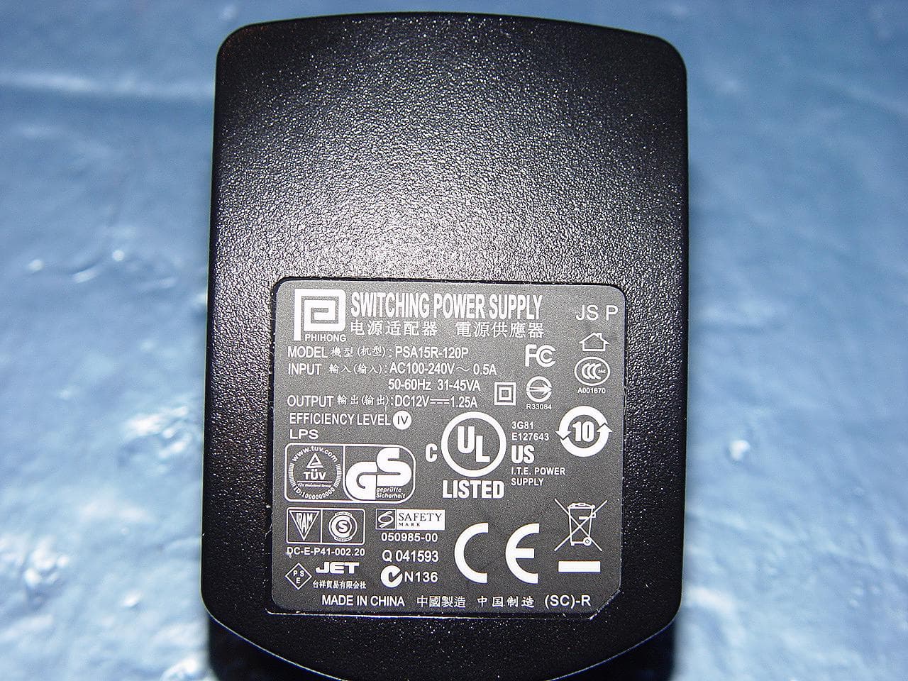
Click to zoom
Application Details
- Equipment Class
- DTS - Digital Transmission System
- Date of Grant
- Feb 17, 2011
- Application Purpose
- Original Equipment
- Date of Application
- Feb 03, 2011
- Equipment Note
- Aruba AP-105 Wireless Access Point
- Frequency Range
- 5745.00000000 - 5825.00000000
- Country
- United States
Documents & Files
Document Text
Text extracted from the exhibit documents filed with the FCC. Open a document above to read the original.
Users Manual
IAP-105 Wireless Access Point Installation Guide About the Aruba IAP-105 Access Points The Aruba IAP-105 wireless access point supports the IEEE 802.11n standard for high-performance WLAN. This access point uses MIMO (Multiple-in, Multiple- out) technology and other high-throughput mode techniques to deliver high- performance, 802.11n 2.4 GHz and 5 GHz functionality while simultaneously supporting existing 802.11a/b/g wireless services. The IAP-105 access point works only in conjunction with an Aruba Controller. The Aruba IAP-105 access point provides the following capabilities: Wireless transceiver Protocol-independent networking functionality IEEE 802.11a/b/g/n operation as a wireless access point IEEE 802.11a/b/g/n operation as a wireless air monitor Compatibility with IEEE 802.3af PoE Central management configuration and upgrades through an Aruba Controller Package Contents IAP-105 access point (1 unit or a pack of 10) Installation guide (this document) Figure 1 IAP-105 IAP-105 Hardware Overview Figure 2 IAP-105 Front LEDs The IAP-105 is equipped with four LEDs that indicate the status of the various components of the AP. PWR: Indicates whether or not the IAP-105 is powered-on ENET: Indicates the status of the IAP-105’s Ethernet port 11A/N: Indicates the status of the 802.11a/n radio 11B/G/N: Indicates the status of the 802.11b/g/n radio For information about the IAP-105’s LED behavior, see Table 1 on page 2. Figure 3 IAP-105 Rear Console Port Use the console port to connect to a terminal for direct local management. Ethernet Port IAP-105 is equipped with a single 10/100/1000Base-T (RJ-45) auto-sensing, MDI/ MDX wired-network connectivity port. This port supports IEEE 802.3af Power over Ethernet (PoE) compliance, accepting 48VDC as a standard defined Powered Device (PD) from a Power Sourcing Equipment (PSE) such as a PoE midspan injector, or network infrastructure that supports PoE. DC Power Socket If PoE is not available, an optional Aruba AP AC-DC adapter kit (sold separately) can be used to power the IAP-105. Reset Button The reset button can be used to return the AP to factory default settings.. To reset the AP: 1. Power off the AP. 2. Press and hold the reset button using a small, narrow object, such as a paperclip. 3. Power-on the AP without releasing the reset button. The power LED will flash within 5 seconds. 4. Release the reset button. The power LED will flash again within 15 seconds indicating that the reset is completed. The AP will now continue to boot with the factory default settings. Before You Begin Pre-Installation Network Requirements After WLAN planning is complete and the appropriate products and their placement have been determined, the Aruba controller(s) must be installed and initial setup performed before the Aruba APs are deployed. For initial setup of the controller, refer to the ArubaOS Quick Start Guide for the software version installed on your controller. AP Pre-Installation Checklist Before installing your IAP-105 access point, be sure that you have the following: CAT5 UTP cable of required length One of the following power sources: IEEE 802.3af-compliant Power over Ethernet (PoE) source Supports full functionality for IAP-105 The POE source can be any power source equipment (PSE) controller or midspan PSE device Aruba AP AC-DC adapter kit (sold separately) Aruba Controller provisioned on the network: Layer 2/3 network connectivity to your access point One of the following network services: Aruba Discovery Protocol (ADP) DNS server with an “A” record DHCP Server with vendor-specific options Summary of the Setup Process Successful setup of an IAP-105 access point consists of five tasks, which must be performed in this order: 1. Verify pre-installation connectivity. 2. Identify the specific installation location for each AP. 3. Install each AP. 4. Verify post-installation connectivity. 5. Configure each AP. Verifying Pre-Installation Connectivity Before you install APs in a network environment, make sure that the APs are able to locate and connect to the controller after power on. Specifically, you must verify the following conditions: When connected to the network, each AP is assigned a valid IP address APs are able to locate the controller Refer to the ArubaOS Quick Start Guide for instructions on locating and connecting to the controller. Identifying Specific Installation Locations You can mount the IAP-105 access point on a wall or on the ceiling. Use the AP placement map generated by Aruba’s RF Plan software application to determine the proper installation location(s). Each location should be as close as possible to the center of the intended coverage area and should be free from obstructions or obvious sources of interference. These RF absorbers/reflectors/interference sources will impact RF propagation and should have been accounted for during the planning phase and adjusted for in RF plan. Identifying Known RF Absorbers/Reflectors/Interference Sources Identifying known RF absorbers, reflectors, and interference sources while in the field during the installation phase is critical. Make sure that these sources are taken into consideration when you attach an AP to its fixed location. RF absorbers include: Cement/concrete—Old concrete has high levels of water dissipation, which dries out the concrete, allowing for potential RF propagation. New concrete has high levels of water concentration within the concrete, blocking RF signals. Natural Items—Fish tanks, water fountains, ponds, and trees Brick RF reflectors include: Metal Objects—Metal pans between floors, rebar, fire doors, air conditioning/ heating ducts, mesh windows, blinds, chain link fences (depending on aperture size), refrigerators, racks, shelves, and filing cabinets Do not place an AP between two air conditioning/heating ducts. Make sure that APs are placed below ducts to avoid RF disturbances. RF interference sources include: Microwave ovens and other 2.4…
Text truncated - open the document above for the full version.
Cover Letter(s)
Letter of Authorization January 26, 2011 Company: Aruba Networks, Inc. Address: 1344 Crossman Ave, Sunnyvale, CA 94089 Model: AP 105 We authorize MiCOM Labs, 440 Boulder Court, Suite 200, Pleasanton, CA 94566, USA, to act on our behalf on all matters concerning the above named equipment. This shall include the following: - Testing - Approval applications and procedures - Payment of approval fees We declare that MiCOM Labs, 440 Boulder Court, Suite 200, Pleasanton, CA 94566, USA, is allowed to forward all information related to the approval project to the applied notified body and to the notification entities and to discuss any issues concerning the approval application. Any and all acts carried out by MiCOM Labs on our behalf shall have the same effect as acts of our own. Sincerely, Signature Name:Ivaylo Tankov Title:Compliance Manager Aruba Networks, Inc. 1344 Crossman Ave., Sunnyvale, CA 94089 Tel: (408) 227 4500 Email: [email protected]
Cover Letter(s)
Federal Communications Commission Equipment Authorization Branch 7435 Oakland Mills Road Columbia, MD 21046 January 26, 2011 Re: SDR Certification Company name: Aruba Networks, Inc. FCC ID: Q9DAP105SDR Gentlemen, In accordance with 0.459 of CFR 47, Aruba Networks, Inc. hereby requests confidentiality of following documents for the subject application: Schematics Block Diagram Theory of Operations Antenna Specification Bill of Materials These documents contain detailed system and equipment description and related information about the product which Aruba Networks considers to be proprietary, confidential and a custom design and otherwise would not release to the general public. Since the design is a basis from which future technological products will evolve, Aruba Networks considers that this information would be of benefit to its competitors and that the disclosure of the information in these documents would give competitors an unfair advantage in the market. Sincerely, Signature Ivaylo Tankov Compliance Manager Aruba Networks, Inc. 1344 Crossman Ave., Sunnyvale, CA 94089 Tel: (408) 227 4500 Email: [email protected]
External Photos
MiCOM Labs, 440 Boulder Court, Suite 200, Pleasanton, CA 94566 Tel: +1 (925) 462-0304, Fax: +1 (925) 462-0306, Web: www.micomlabs.com the wireless lab 4 February 2011 IAP-105 External Photographs Aruba Networks IAP-105 Wireless Access Point (Front) Page 2 of 3 the wireless lab Aruba Networks AP-105 Wireless Access Point (Rear) Page 3 of 3 the wireless lab Power supply
ID Label/Location Info
MiCOM Labs, 440 Boulder Court, Suite 200, Pleasanton, CA 94566 Tel: +1 (925) 462-0304, Fax: +1 (925) 462-0306, Web: www.micomlabs.com the wireless lab 2/4/2011 The device is electronically labeled and the FCC ID will be displayed via the controller WebUI under the About menu. 784748 D01 Labelling Part 15 &18 Guidelines v07 A software defined radio (Section 2.944) may provide permanently affixed labels according to standard Certification labelling requirements (see 2.2 Certification (labelling requirements) above) or electronic labelling. An electronic label may use a built-in display on the device or provide a standard electrical interface. The electrical interface must be an industry standard using commonly used protocols and methods to permit easy local access (http through a browser, Telnet or ASCII serial interface using standard terminal emulation, Hyper terminal, etc.) The user manual must provide a description of the method for using basic commands to access the FCC ID. Access to the FCC ID shall be obtained without any security (user name, password, etc.) unless all types of access require some security, then access to the FCC ID must be obtained through the lowest security level defined for the end user of the system.
Internal Photos
MiCOM Labs, 440 Boulder Court, Suite 200, Pleasanton, CA 94566 Tel: +1 (925) 462-0304, Fax: +1 (925) 462-0306, Web: www.micomlabs.com the wireless lab 4 February 2011 IAP-105 Internal Photographs Aruba Networks Internal View Page 2 of 5 the wireless lab Main Assembly Bottom Page 3 of 5 the wireless lab Main Assembly Top Page 4 of 5 the wireless lab RF Assembly Bottom Page 5 of 5 the wireless lab RF Assembly Top
RF Exposure Info
MiCOM Labs, 440 Boulder Court, Suite 200, Pleasanton, CA 94566 Tel: +1 (925) 462-0304, Fax: +1 (925) 462-0306, Web: www.micomlabs.com the wireless lab Maximum Permissible Exposure FCC, Part 15 Subpart C §15.247(i) Industry Canada RSS-Gen §5.5 Calculations for Maximum Permissible Exposure Levels Power Density = Pd (mW/cm 2 ) = EIRP/(4πd 2 ) EIRP = P * G P = Peak output power (mW) G = Antenna numeric gain (numeric) d = Separation distance (cm) Numeric Gain = 10 ^ (G (dBi)/10) The Aruba AP-105 has two transmitters operating in each band. The peak power in the table below is calculated by assuming a worst case scenario where the two transmitters are operating simultaneously in the same band. The Peak Power in mW is calculated by taking the maximum allowable conducted power measured in each band and multiplying by 2. Because the EUT belongs to the General Population/Uncontrolled Exposure the limit of power density is 1.0 mW/cm 2 Freq. Band (GHz) Antenna Gain (dBi) Numeric Gain (numeric) Peak Output Power (dBm) Peak Output Power (mW) Calculated Safe Distance @ 1mW/cm 2 Limit(cm) Minimum Separation Distance (cm) 2.4 2.5 1.78 +19.81 191.5 5.2 20.0* 5.8 4.0 2.51 +18.51 141.9 5.3 20.0* *Note: for mobile or fixed location transmitters the minimum separation distance is 20cm, even if calculations indicate the MPE distance to be less. Specification Maximum Permissible Exposure Limits §15.247(i) Systems operating under the provisions of this section shall be operated in a manner that ensures that the public is not exposed to radio frequency levels in excess of the Commission’s guidelines. FCC §1.1310 Limit = 1mW / cm 2 from 1.310 Table 1 RSS-Gen §5.5 Before equipment certification is granted, the applicable requirements of RSS-102 shall be met
Test Report
COVER PAGE Test of Aruba AP-105 802.11a/b/g/n Wireless AP To: FCC 47 CFR Part 15.247 & IC RSS-210 Test Report Serial No.: ARUB40-A2 Rev A TITLE PAGE TEST REPORT FROM Test of Aruba AP-105 802.11a/b/g/n Wireless AP to To FCC 47 CFR Part 15.247 & IC RSS-210 Test Report Serial No.: ARUB40-A2 Rev A Note: this report contains data with regard to the 2400 to 2483.5 MHz and 5725 to 5850 MHz operational modes of the Aruba Networks AP-105 Wireless Access Point. 5,150 to 5,250 MHz test data is reported in MiCOM Labs test report ARUB40-A4. This report supersedes: NONE Applicant: Aruba Networks, Inc 1344 Crossman Avenue Sunnyvale California 94089, USA Product Function: Wireless Access Point Copy No: pdf Issue Date: 10th September 2009 MiCOM Labs is an ISO 17025 Accredited Testing Laboratory This Test Report is Issued Under the Authority of; MiCOM Labs, Inc. 440 Boulder Court, Suite 200 Pleasanton, CA 94566 USA Phone: +1 (925) 462-0304 Fax: +1 (92 5 ) 462-0306 www.micomlabs.com CERTIFICATE #2381.01 This test report may be reproduced in full only. The document may only be updated by MiCOM Labs personnel. Any changes will be noted in the Document History section of the report. Title: Aruba AP-105 802.11a/b/g/n Wireless AP To: Serial #: Issue Date: Page: FCC 47 CF R Part 15.247 & IC RSS-210 ARUB40- A2 Rev A 10th September 2009 3 of 177 This test report may be reproduced in full only. The document may only be updated by MiCOM Labs personnel. Any changes will be noted in the Document History section of the report. MiCOM Labs, 440 Boulder Court, Suite 200, Pleasanton, CA 94566 USA, Phone: 925.462.0304, Fax: 925.462.0306, www.micomlabs.com This page has been left intentionally blank Title: Aruba AP-105 802.11a/b/g/n Wireless AP To: Serial #: Issue Date: Page: FCC 47 CF R Part 15.247 & IC RSS-210 ARUB40- A2 Rev A 10th September 2009 4 of 177 This test report may be reproduced in full only. The document may only be updated by MiCOM Labs pe rsonnel. Any changes will be noted in the Document History section of the report. MiCOM Labs, 440 Boulder Court, Suite 200, Pleasanton, CA 94566 USA, Phone: 925.462.0304, Fax: 925.462.0306, www.micomlabs.com TABLE OF CONTENTS ACCREDITATION, LISTINGS & RECOGNITION ............................................................ 5 1. TEST RESULT CERTIFICATE ................................................................................... 8 2. REFERENCES AND MEASUREMENT UNCERTAINTY .......................................... 9 2.1. Normative References ............................................................................................... 9 2.2. Test and Uncertainty Procedures .............................................................................. 9 3. PRODUCT DETAILS AND TEST CONFIGURATIONS .......................................... 10 3.1. Technical Details ..................................................................................................... 10 3.2. Scope of Test Program ............................................................................................ 11 3.3. Equipment Model(s) and Serial Number(s) ............................................................. 12 3.4. Antenna Details ....................................................................................................... 12 3.5. Cabling and I/O Ports .............................................................................................. 12 3.6. Test Configurations.................................................................................................. 13 3.7. Equipment Modifications.......................................................................................... 23 3.8. Deviations from the Test Standard .......................................................................... 24 3.9. Subcontracted Testing or Third Party Data ............................................................. 24 4. TEST SUMMARY ...................................................................................................... 25 5. TEST RESULTS ........................................................................................................ 27 5.1. Device Characteristics ............................................................................................. 27 5.1.1. 6 dB and 99 % Bandwidth ........................................................................27 5.1.2. Peak Output Power ..................................................................................50 5.1.3. Peak Power Spectral Density...................................................................56 5.1.4. Maximum Permissible Exposure ..............................................................79 5.1.5. Conducted Spurious Emissions ...............................................................80 5.1.6. Radiated Emissions ...............................................................................117 5.1.7. AC Wireline Conducted Emissions (150 kHz – 30 MHz)........................173 6. TEST EQUIPMENT DETAILS................................................................................. 176 Title: Aruba AP-105 802.11a/b/g/n Wireless AP To: Serial #: Issue Date: Page: FCC 47 CF R Part 15.247 & IC RSS-210 ARUB40- A2 Rev A 10th September 2009 5 of 177 This test report may be reproduced in full only. The document may only be updated by MiCOM Labs pe rsonnel. Any changes will be noted in the Document History section of the report. MiCOM Labs, 440 Boulder Court, Suite 200, Pleasanton, CA 94566 USA, Phone: 925.462.0304, Fax: 925.462.0306, www.micomlabs.com ACCREDITATION, LISTINGS & RECOGNITION ACCREDITATION MiCOM Labs, Inc. an accredited laboratory complies with the international standard EN ISO/IEC 17025. The company is accredited by the American Association for Laboratory Accreditation (A2LA) www.a2la.org test laboratory number 2381.01. MiCOM Labs test schedule is available at the following URL; http://www.a2la.org/scopepdf/2381-01.pdf Title: Aruba AP-105 802.11a/b/g/n Wireless A…
Text truncated - open the document above for the full version.
Test Report
COVER PAGE Test of Aruba IAP-105 802.11a/b/g/n Wireless AP To: FCC CFR 47 Part 15 & IC RSS-210 Test Report Serial No.: ARUB69-U1 Rev A TITLE PAGE TEST REPORT FROM Test of Aruba IAP-105 802.11a/b/g/n Wireless AP to To FCC CFR 47 Part 15 & IC RSS-210 Test Report Serial No.: ARUB69-U1 Rev A This report supersedes: NONE Applicant: Aruba Networks, Inc 1344 Crossman Avenue Sunnyvale California 94089, USA Product Function:Transmitting data and voice traffic Copy No: pdf Issue Date: 2nd February 2011 This Test Report is Issued Under the Authority of; MiCOM Labs is an ISO 17025 Accredited Testing Laboratory TESTING CERTIFICATE #2381.01 MiCOM Labs, Inc. 440 Boulder Court, Suite 200 Pleasanton, CA 94566 USA Phone: +1 (925) 462-0304 Fax: +1 (925) 462-0306 www.micomlabs.com This test report may be reproduced in full only. The document may only be updated by MiCOM Labs personnel. Any changes will be noted in the Document History section of the report. Title: Aruba IAP-105 802.11a/b/g/n Wireless AP To: Serial #: Issue Date: Page: FCC CFR 4 7 Part 15 & IC RSS-210 ARUB69-U1 Rev A 2nd February 2011 3 of 25 This test report may be reproduced in full only. The document may only be updated by MiCOM Labs personnel. Any changes will be noted in the Document History section of the report. MiCOM Labs, 440 Boulder Court, Suite 200, Pleasanton, CA 94566 USA, Phone: 925.462.0304, Fax: 925.462.0306, www.micomlabs.com This page has been left intentionally blank Title: Aruba IAP-105 802.11a/b/g/n Wireless AP To: Serial #: Issue Date: Page: FCC CFR 4 7 Part 15 & IC RSS-210 ARUB69-U1 Rev A 2nd February 2011 4 of 25 This test report may be reproduced in full only. The document may only be updated by MiCOM Labs p ersonnel. Any changes will be noted in the Document History section of the report. MiCOM Labs, 440 Boulder Court, Suite 200, Pleasanton, CA 94566 USA, Phone: 925.462.0304, Fax: 925.462.0306, www.micomlabs.com TABLE OF CONTENTS ACCREDITATION, LISTINGS & RECOGNITION ............................................................ 5 TESTING ACCREDITATION ........................................................................................... 5 RECOGNITION ................................................................................................................. 6 PRODUCT CERTIFICATION ............................................................................................ 7 1. TEST RESULT CERTIFICATE ................................................................................... 9 2. REFERENCES AND MEASUREMENT UNCERTAINTY ........................................ 10 2.1. Normative References ............................................................................................. 10 2.2. Test and Uncertainty Procedures ............................................................................ 11 3. PRODUCT DETAILS AND TEST CONFIGURATIONS .......................................... 12 3.1. Technical Details ..................................................................................................... 12 3.2. Scope of Test Program ............................................................................................ 13 3.3. Equipment Model(s) and Serial Number(s) ............................................................. 14 3.4. Antenna Details ....................................................................................................... 14 3.5. Cabling and I/O Ports .............................................................................................. 14 3.6. Test Configurations.................................................................................................. 15 3.7. Deviations from the Test Standard .......................................................................... 15 3.8. Subcontracted Testing or Third Party Data ............................................................. 15 4. TEST SUMMARY ...................................................................................................... 16 5. TEST RESULTS ........................................................................................................ 17 5.1. Device Characteristics ............................................................................................. 17 5.1.1. Radiated Spurious Emissions (0.03 - 1 GHz, 1 – 6 GHz) ........................17 6. PHOTOGRAPHS....................................................................................................... 22 6.1. Radiated Emissions > 1GHz.................................................................................... 22 6.2. Radiated Emissions < 1GHz.................................................................................... 23 7. TEST EQUIPMENT DETAILS................................................................................... 24 Title: Aruba IAP-105 802.11a/b/g/n Wireless AP To: Serial #: Issue Date: Page: FCC CFR 4 7 Part 15 & IC RSS-210 ARUB69-U1 Rev A 2nd February 2011 5 of 25 This test report may be reproduced in full only. The document may only be updated by MiCOM Labs p ersonnel. Any changes will be noted in the Document History section of the report. MiCOM Labs, 440 Boulder Court, Suite 200, Pleasanton, CA 94566 USA, Phone: 925.462.0304, Fax: 925.462.0306, www.micomlabs.com ACCREDITATION, LISTINGS & RECOGNITION TESTING ACCREDITATION MiCOM Labs, Inc. is an accredited Electrical testing laboratory per the international standard EN ISO/IEC 17025. The company is accredited by the American Association for Laboratory Accreditation (A2LA) www.a2la.org test laboratory number 2381.01. MiCOM Labs test schedule is available at the following URL; http://www.a2la.org/scopepdf/2381-01.pdf Title: Aruba IAP-105 802.11a/b/g/n Wireless AP To: Serial #: Issue Date: Page: FCC CFR 4 7 Part 15 & IC RSS-210 ARUB69-U1 Rev A 2nd February 2011 6 of 25 This test report may be reproduced in full only. The document may only be updated by MiCOM Labs p ersonnel. Any changes will be noted in the Document Hist…
Text truncated - open the document above for the full version.
Test Setup Photos
MiCOM Labs, 440 Boulder Court, Suite 200, Pleasanton, CA 94566 Tel: +1 (925) 462-0304, Fax: +1 (925) 462-0306, Web: www.micomlabs.com the wireless lab 4 February 2011 IAP-105 Test Set Up Photographs Radiated Emissions > 1GHz Page 2 of 4 the wireless lab Radiated Emissions < 1GHz Page 3 of 4 the wireless lab AC Wireline Conducted Emissions Page 4 of 4 the wireless lab Conducted RF Measurement Test Set-Up
Contact Information
Applicant
Mark Hill(Principal Engineer)
Test Firm
Micom LabsGordon Hurst
Technical Specifications
| # | Rule Parts | Frequency Range | Power Output | Emission | Tolerance |
|---|---|---|---|---|---|
| 3 | 15C | 5.75 GHz - 5.83 GHz | 71.00 mW | 36M3D1D | 20 ppm |
Other Applications from Hewlett Packard Enterprise Company
Q9DAPINH721
Jul 17, 2026Access Point
Equipment Class
6ID - 15E 6 GHz Low Power Indoor Access PointQ9DASIN0307
Dec 22, 2025HPE Aruba User Experience Sensor
Equipment Class
DTS - Digital Transmission SystemQ9DASIN0308
Nov 23, 2025HPE Aruba User Experience Sensor
Equipment Class
DTS - Digital Transmission SystemQ9DAPEX0764
Nov 20, 2025ACCESS POINT
Equipment Class
DTS - Digital Transmission SystemQ9DAPIN0763
Sep 29, 2025ACCESS POINT
Equipment Class
NII - Unlicensed National Information Infrastructure TX