Q9DAP175802.11 a/b/g/n Wireless Access Point
Hewlett Packard Enterprise Company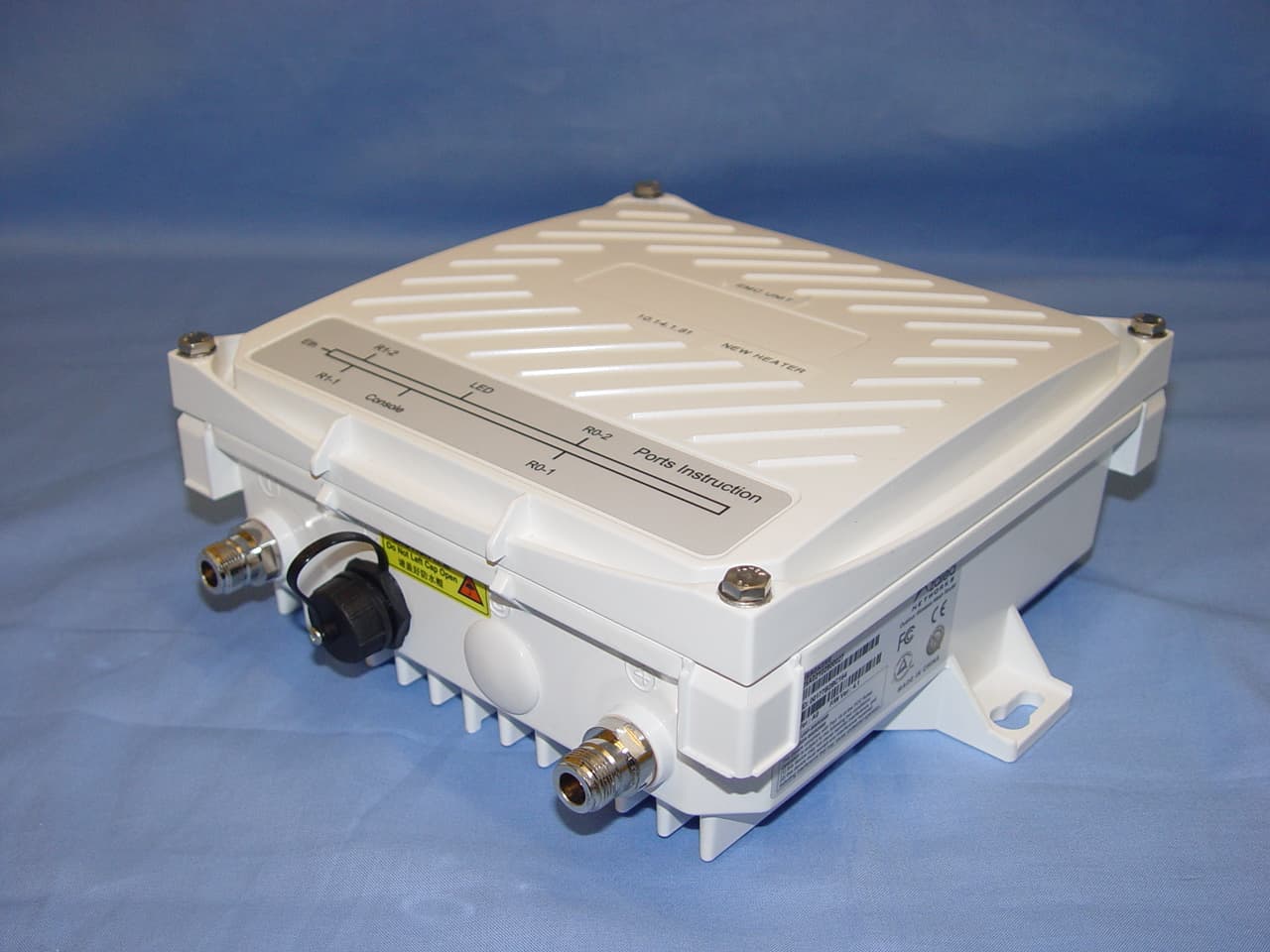
Click to zoom
Application Details
- Equipment Class
- DTS - Digital Transmission System
- Date of Grant
- Nov 10, 2010
- Application Purpose
- Original Equipment
- Date of Application
- Nov 10, 2010
- Equipment Note
- 802.11 a/b/g/n Wireless Access Point
- Frequency Range
- 5745.00000000 - 5825.00000000
- Country
- United States
Documents & Files
Document Text
Text extracted from the exhibit documents filed with the FCC. Open a document above to read the original.
Users Manual
Aruba AP-175 Outdoor Access Point Installation Guide 0510795-01| September 20101 The Aruba AP-175 is a resilient, environmentally hardened, outdoor rated, dual-radio, dual-band IEEE 802.11 a/b/g/n wireless access point. This outdoor access point is part of Aruba’s comprehensive wireless network solution. The AP-175 works only in conjunction with an Aruba controller and each AP can be centrally managed, configured, and upgraded through the controller. There are three versions of the AP-175, which mainly differ in the way they receive power. zAP-175P: PoE+ powered (802.3at) zAP-175AC: AC powered (100 - 240 VAC) zAP-175DC: DC powered (12 - 48 VDC) Guide Overview z"AP-175 Hardware Overview" on page 2 provides a detailed hardware overview of the three AP-175 models. z"Outdoor Planning and Deployment Considerations" on page 5 provides key questions to ask and items to consider when deploying an outdoor wireless network. z"Installing the AP-175" on page 9 describes the multi-step process for a successful installation and deployment of an AP-175. z"Safety and Regulatory Compliance" on page 15 provides an overview of safety and regulatory compliance information. AP-175 Operations zWireless access point (IEEE 802.11 a/b/g/n) zWireless air monitor (IEEE 802.11 a/b/g/n) zEnterprise mesh point zEnterprise mesh portal zProtocol-independent networking functionality zAP-175P: IEEE 802.3at Power over Ethernet+ (PoE+) compatible zAP-175AC and AP-175DC: IEEE 802.3af Power Sourcing Equipment (PSE) device NOTE The AP-175AC/DC can function as a Power Sourcing Equipment (PSE) device by providing power through its Ethernet port in compliance with the IEEE 802.3af standard. AP-175-IG-Rev01.fm Page 1 Friday, September 17, 2010 4:27 PM 2Aruba AP-175 Outdoor Access Point| Installation Guide Package Contents zAP-175 Access Point zAP-175 Mounting Bracket zSolar Shield zPole Anchors x 2 zM4 x 16 bolts, flat washers, and spring washers x4 (These bolts are attached to the solar shield) zM6 x 30 bolts, flat washers, and spring washers x2 zM4 x 12 bolt, external-tooth washer, and OT copper lug x1 zM8 x 110 bolt, flat washers, spring washers, and nuts x4 zInstallation Guide AP-175 Hardware Overview The following section describes the hardware features of the AP-175. Figure 1 AP-175 Overview NOTE Inform your supplier if there are any incorrect, missing, or damaged parts. If possible, retain the carton, including the original packing materials. Use these materials to repack and return the unit to the supplier if needed. 1Antenna Interface (Radio 1)5Antenna Interface (Radio 0) 2USB Console Interface6Antenna Interface (Radio 1) 3Reserved (AP-175P) or Power Interface (AP-175AC and AP-175DC) 7Ethernet Interface (PoE) 4Antenna Interface (Radio 0)8Grounding Point 2 1 3 4 8 7 6 5 AP-175-IG-Rev01.fm Page 2 Friday, September 17, 2010 4:27 PM Aruba AP-175 Outdoor Access Point| Installation Guide3 Antenna Interface The AP-175 requires the use of detachable outdoor-rated antennas. Select the correct antenna type to support the required frequency band (2.4 or 5 GHz) and the desired coverage pattern. The AP-175 is equipped with four, female N-type antenna interfaces; two on the top of the AP and two on the bottom. The interfaces are grouped into diversity pairs, one pair is marked R0 (Radio 0) and the other pair marked as R1 (Radio 1). R0 supports the 5 GHz frequency band and R1 supports the 2.4 GHz radio band. USB Console Interface A USB serial console port is provided for connection to a terminal, allowing direct local management. Use the following setting to access the terminal: Power Interface The type of power interface on your AP-175 depends on which model you have purchased. zAP-175P: This version does not include a power interface since it is only powered by PoE+ (802.3at). zAP-175AC: 1x AC power connector zAP-175DC: 1x DC power connector Ethernet Interface The AP-175 is equipped with a 10/100/1000Base-T Gigabit Ethernet port for wired network connectivity. On the AP-175P, this port also supports IEEE 802.3at Power over Ethernet (PoE), accepting 48 VDC as a standards-defined powered device (PD) from a power sourcing equipment (PSE) device, such as a PoE midspan injector. Inversely, the AP-175AC and AP-175DC can act as a PSE device to provide IEEE802.3af PoE power to devices connected to the Ethernet port. Grounding Point Always remember to protect your AP-175 by installing grounding lines. The ground connection must be complete before connecting power to the AP-175 enclosure. Ensure that the resistance is less than 5 ohm between the ground termination point and the grounding tier. LED Status Indicators The AP-175 include visual indicators for power, link, and radio status. Additionally, each radio has a four- LED array that indicates received signal strength (RSSI). Table 1 Console Settings Baud RateData BitsParityStop BitsFlow Control 96008None1 None NOTE The RSSI LED indicators represent varying degrees in the RSSI level. The absence of a signal is indicated by no LED response, and full signal strength is indicated when all four LEDs are active and lit. AP-175-IG-Rev01.fm Page 3 Friday, September 17, 2010 4:27 PM 4Aruba AP-175 Outdoor Access Point| Installation Guide Figure 2 LED Layout Table 2 lists the meanings of the LEDs on the AP-175 outdoor access points. Table 2 AP-175 LED Status Indicators LEDFunctionIndicatorStatus P/SAP Power/Ready Status OffNo power to AP BlinkingDevice booting, not ready OnDevice ready ENTLAN/Network Link Status OffEthernet link unavailable On (Amber)10/100 Mbs Ethernet link negotiated On (Green)1000 Mbs Ethernet link negotiated BlinkingTraffic on Ethernet link R0Radio 0 StatusOffRadio 0 disabled On (Amber)Radio 0 enabled in WLAN mode BlinkingAir Monitor (AM) mode R1Radio 1 StatusOffRadio 1disabled On (Blue)Radio 1 enabled in WLAN mode BlinkingAir Monitor (AM) mode RSSI (Radio 0)RSSI Level for Radio 0 OffRSSI disabled/no signal 4 Step Progressive Bars (Red) 25/50/75/100% Each bar represents a progres…
Text truncated - open the document above for the full version.
Attestation Statements
DECLARATION November 8, 2010 Re: miniPCI RF Radio Module Company name: Aruba Networks, Inc. FCC ID: Q9DAP175 IC: 4675A-AP175 TO WHOM IT MAY CONCERN Aruba Networks Inc., hereby declare that devices certified under the FCC ID and Industry Canada Certification numbers listed above use the unmodified WLAN 802.11 a/b/g/n miniPCI module model DNMA-H92 manufactured by Winstron NeWb Corporation. Sincerely, Signature Ivaylo Tankov Compliance Manager Aruba Networks, Inc. 1344 Crossman Ave., Sunnyvale, CA 94089
Cover Letter(s)
Federal Communications Commission Authorization and Evaluation Division Equipment Authorization Branch 7435 Oakland Mills Road Columbia, MD 21046 11/4/2010 To whom it may concern: We, the undersigned, hereby authorize Eurofins ETS Product Service GmbH to act on our behalf in all matters relating to applications for equipment authorization FCC ID: Q9DAP175 including the signing of all documents related to these matters. Any and all acts carried out by Eurofins ETS Product Service GmbH on our behalf shall have the same effect as acts of our own. We also hereby certify that no party to this application is subject to a denial of benefits, including FCC benefits, pursuant to Section 5301 of the Anti-Drug Abuse Act of 1988, 21 U.S.C. 862. Sincerely, Signature Agnes Fu Compliance Engineer Aruba Networks, Inc.
Cover Letter(s)
Federal Communications Commission Equipment Authorization Branch 7435 Oakland Mills Road Columbia, MD 21046 27.10.2010 Re: Request for Confidentiality Company name: Aruba Networks, Inc. FCC ID: Q9DAP175 Gentlemen, In accordance with 0.459 of CFR 47, Aruba Networks, Inc. hereby requests confidentiality of following documents for the subject application: Schematics Block Diagram Theory of Operations Bill of Materials These documents contain detailed system and equipment description and related information about the product which Aruba Networks considers to be proprietary, confidential and a custom design and otherwise would not release to the general public. Since the design is a basis from which future technological products will evolve, Aruba Networks considers that this information would be of benefit to its competitors and that the disclosure of the information in these documents would give competitors an unfair advantage in the market. Sincerely, Signature Ivaylo Tankov Compliance Manager Aruba Networks, Inc. 1344 Crossman Ave., Sunnyvale, CA 94089
External Photos
the wireless lab 8 November 2010 External Photographs Aruba Networks, Inc. AP-175P & MSR2K23NO-XX Front External View MiCOM Labs, 440 Boulder Court, Suite 200, Pleasanton, CA 94566 Tel: +1 (925) 462-0304, Fax: +1 (925) 462-0306, Web: www.micomlabs.com the wireless lab Side View 1 Page 2 of 4 the wireless lab Side View 2 Page 3 of 4 the wireless lab Back View Page 4 of 4
ID Label/Location Info
LABEL,DEVICE,ARUBA,AP-175P COLOR OF BASE: MATERIAL PRIMARY COLOR OF FONT: BLACK Out the direction SILVER MATT PET,T=0.05, BACKSIDE ADHESIVE MATERIAL 85.5mm 40.0mm R 2.0mm,4PLS 5. UL APPROVED INK & MATERIAL AP-175P Q9DAP175 4675A-AP175 AP-175P Q9DAP175 4675A-AP175 ARUBA NETWORKS, INC. MODEL: AP-175P SPEC: 48V ;0.5A FCC ID: Q9DAP175 IP66 IC: 4675A-AP175 This device complies with Part 15 of the FCC Rules. Operation is subject to the following two conditions: (1) this device may not cause harmful interference, and (2) this device must accept any interference received, including interference that may cause undesired operations. MADE IN CHINA SN: XXXXXXXXXXXXXX XXXXXXXXXXXX MAC: P0 N19592 R 003ZWA100834 003BVA100835 003DVA100836 003WWA100832 003XWA100833
Internal Photos
the wireless lab 22 October 2010 Internal Photographs Aruba Networks, Inc. AP-175P & MSR2K23NO-XX Internal View MiCOM Labs, 440 Boulder Court, Suite 200, Pleasanton, CA 94566 Tel: +1 (925) 462-0304, Fax: +1 (925) 462-0306, Web: www.micomlabs.com the wireless lab Cable PCB Assy Bottom Page 2 of 9 the wireless lab Cable PCB Assy Top Page 3 of 9 the wireless lab Configuration Switch Assy Page 4 of 9 the wireless lab Motherbrd Assy Bottom Page 5 of 9 the wireless lab Motherbrd Assy Top Page 6 of 9 the wireless lab POE Assy Top Page 7 of 9 the wireless lab RF Assy Bottom Page 8 of 9 the wireless lab RF Assy Top Page 9 of 9
Parts List/Tune Up Info
Federal Communications Commission Equipment Authorization Branch 7435 Oakland Mills Road Columbia, MD 21046 November 5, 2010 Re: Antenna list Company name: Aruba Networks, Inc. FCC ID: Q9DAP175 Gentlemen, The following is a description and list of antennas to be used with FCC ID: Q9DAP175 Antenna Type Manufacturer Model Gain (dBi) Frequency Range (MHz) Dipole Aruba Networks Inc. AP-ANT-80D 8 2400 - 2500 Dipole Aruba Networks Inc. AP-ANT-86 9 4900 – 5900 Directional Aruba Networks Inc. AP-ANT-85 15 2400 – 2500 Directional Aruba Networks Inc.AP-ANT-89144900 – 5900 Directional Aruba Networks Inc. ANT-2x2-5714 14 4900 – 5900 Sincerely, Signature Ivaylo Tankov Compliance Manager Aruba Networks, Inc. 1344 Crossman Ave., Sunnyvale, CA 94089
RF Exposure Info
the wireless lab Maximum Permissible Exposure FCC, Part 15 Subpart C §15.247section (i) Industry Canada RSS-Gen §5.5 Calculations for Maximum Permissible Exposure Levels Power Density = Pd (mW/cm 2 ) = EIRP/(4πd 2 ) EIRP = P * G * 2 P = Peak output power (mW) G = Antenna numeric gain (numeric) d = Separation distance (cm) Numeric Gain = 10 ^ (G (dBi)/10) The Aruba AP-175P / MSR2K23N0-XX has two transmitters. The peak power used in the table below is the highest conducted level used to meet the EIRP requirements. Because the EUT belongs to the General Population/Uncontrolled Exposure the limit of power density is 1.0 mW/cm 2 Freq. Band (MHz) Antenna Gain (dBi) Antenna Numeric Gain (numeric) Peak Output Power (dBm) Peak Output Power (mW) Calculated Safe Distance @ 1mW/cm 2 Limit(cm) Minimum Separation Distance (cm) 2400 – 2500 15.0 31.62 +20.7 117.5 17.2 20.00 5725 - 5850 13.25 21.10 +22.1 162.2 16.5 20.00 Note: for mobile or fixed location transmitters the minimum separation distance is 20cm, even if calculations indicate the MPE distance to be less. Specification Maximum Permissible Exposure Limits FCC §1.1310 Limit = 1mW / cm 2 from 1.310 Table 1 RSS-Gen §5.5 Before equipment certification is granted, the application requirements of RSS-102 shall be met. Laboratory Measurement Uncertainty for Power Measurements Measurement uncertainty ±1.33 dB MiCOM Labs, 440 Boulder Court, Suite 200, Pleasanton, CA 94566 Tel: +1 (925) 462-0304, Fax: +1 (925) 462-0306, Web: www.micomlabs.com
Test Report
SPORTON International Inc. No. 52, Hwa Ya 1st Rd., Kwei-Shan Hsiang, TaoYuan Hsien, Taiwan, R.O.C. Ph: 886-3-327-3456 / FAX: 886-3-327-0973 / www.sporton.com.tw Report Format Version: 01 FCC RADIO TEST REPORT Applicant’s company Wistron NeWeb Corporation Applicant Address No. 10-1, Li-hsin Road I, Hsinchu Science Park, Hsinchu 300, Taiwan, R.O.C. FCC ID NKR-DNMAH92 Manufacturer’s company Wistron NeWeb Corporation Manufacturer Address No. 10-1, Li-hsin Road I, Hsinchu Science Park, Hsinchu 300, Taiwan, R.O.C. Product Name WLAN 802.11a/b/g/n MiniPCI module Brand Name WNC Model Name DNMA-H92 Test Rule Part(s) 47 CFR FCC Part 15 Subpart C § 15.247 Test Freq. Range 2400 ~ 2483.5MHz / 5725 ~ 5850MHz Received Date Nov. 20, 2009 Final Test Date Dec. 07, 2009 Submission Type Original Equipment Statement Test result included is only for the 802.11n, 802.11b/g part and 802.11a (5725 ~ 5850MHz) of the product. The test result in this report refers exclusively to the presented test model / sample. Without written approval of SPORTON International Inc., the test report shall not be reproduced except in full. The measurements and test results shown in this test report were made in accordance with the procedures and found in compliance with the limit given in ANSI C63.4-2003 and 47 CFR FCC Part 15 Subpart C. The test equipment used to perform the test is calibrated and traceable to NML/ROC. Report No.: FR9N1919-01AB Report Format Version: 01 Page No. : i of ii FCC ID: NKR-DNMAH92 Issued Date : Dec. 18, 2009 Table of Contents 1. CERTIFICATE OF COMPLIANCE ......................................................................................................................... 1 2. SUMMARY OF THE TEST RESULT .......................................................................................................................... 2 3. GENERAL INFORMATION .................................................................................................................................. 3 3.1. Product Details....................................................................................................................................................................................3 3.2. Accessories .........................................................................................................................................................................................5 3.3. Table for Filed Antenna.......................................................................................................................................................................6 3.4. Table for Carrier Frequencies .............................................................................................................................................................7 3.5. Table for Test Modes ...........................................................................................................................................................................8 3.6. Table for Testing Locations..................................................................................................................................................................9 3.7. Table for Supporting Units ...................................................................................................................................................................9 3.8. Table for Parameters of Test Software Setting ...................................................................................................................................10 3.9. Test Configurations ...........................................................................................................................................................................11 4. TEST RESULT ................................................................................................................................................... 14 4.1. AC Power Line Conducted Emissions Measurement.........................................................................................................................14 4.2. Maximum Conducted Output Power Measurement .........................................................................................................................18 4.3. Power Spectral Density Measurement ..............................................................................................................................................46 4.4. 6dB Spectrum Bandwidth Measurement ..........................................................................................................................................60 4.5. Radiated Emissions Measurement ....................................................................................................................................................73 4.6. Band Edge Emissions Measurement ...............................................................................................................................................119 4.7. Antenna Requirements ...................................................................................................................................................................131 5. LIST OF MEASURING EQUIPMENTS ................................................................................................................. 132 6. TEST LOCATION............................................................................................................................................ 133 7. TAF CERTIFICATE OF ACCREDITATION ........................................................................................................... 134 APPENDIX A. PHOTOGRAPHS OF EUT.......................................................................................................... A1 ~ A6 APPENDIX B. TEST PHOTOS.......................................................................................................................... B1 ~ B6 APPENDIX C. MAXIMUM PERMISSI…
Text truncated - open the document above for the full version.
Test Report
Test of Aruba AP-175P / MSR2K23N0-XX 802.11a/b/g/n Wireless AP To: FCC 47 CFR Part 15.247 & IC RSS-210 Test Report Serial No.: ARUB61-U1 Rev A This test report may be reproduced in full only. The document may only be updated by MiCOM Labs personnel. Any changes will be noted in the Document History section of the report. TEST REPORT FROM Test of: Aruba Networks, Inc AP-175P / MSR2K23N0-XX 802.11a/b/g/n Wireless AP To: FCC 47 CFR Part 15.247 & IC RSS 210 Test Report Serial No.: ARUB61-U1 Rev A This report supersedes: NONE Applicant: Aruba Networks, Inc 1344 Crossman Avenue Sunnyvale , CA 94089 USA Product Function: Wireless Access Point Copy No: pdf Issue Date: 1st November 2010 TESTING CERTIFICATE #2381.01 MiCOM Labs is an ISO 17025 Accredited Testing Laboratory This Test Report is Issued Under the Authority of; MiCOM Labs, Inc. 440 Boulder Court, Suite 200 Pleasanton, CA 94566 USA Phone: +1 (925) 462-0304 Fax: +1 (925) 462-0306 www.micomlabs.com Title: AP-175P / MSR2K23N0-XX 802.11a/b/g/n AP To: FCC 47 CFR Part 15.247 & IC RSS-210 Serial #: ARUB61-U1 Rev A Issue Date: 1st November 2010 Page: Page 3 of 144 This test report may be reproduced in full only. The document may only be updated by MiCOM Labs personnel. Any changes will be noted in the Document History section of the report. MiCOM Labs, 440 Boulder Court, Suite 200, Pleasanton, CA 94566 USA, Phone: 925.462.0304, Fax: 925.462.0306, www.micomlabs.com TABLE OF CONTENTS 1 ACCREDITATION, LISTINGS & RECOGNITION ..................................................... 4 1.1 ACCREDITATION ..................................................................................................... 4 1.2 LISTINGS .................................................................................................................. 5 1.3 RECOGNITION ......................................................................................................... 5 2 DOCUMENT HISTORY ............................................................................................... 6 3 TEST RESULT CERTIFICATE ................................................................................... 7 4 REFERENCES AND MEASUREMENT UNCERTAINTY .......................................... 8 4.1 Normative References ............................................................................................... 8 4.2 Test and Uncertainty Procedures .............................................................................. 9 5 TEST SUMMARY ...................................................................................................... 10 6 PRODUCT DETAILS AND TEST CONFIGURATIONS .......................................... 11 6.1 EUT Details.............................................................................................................. 11 6.2 Scope of Test Program ............................................................................................ 12 6.3 Equipment Model(s) and Serial Number(s) ............................................................. 13 6.4 Antenna Details ....................................................................................................... 13 6.5 Cabling and I/O Ports .............................................................................................. 14 6.6 Test Configurations.................................................................................................. 14 6.7 Equipment Modifications.......................................................................................... 15 6.8 Deviations from the Test Standard .......................................................................... 15 7 TEST RESULTS ........................................................................................................ 16 7.1 Maximum Transmit Power (EIRP) ........................................................................... 16 7.2 Maximum Permissible Exposure ............................................................................. 19 7.3 Radiated Spurious Emissions - Radio Device ......................................................... 20 7.4 Radiated Spurious Emissions – Digital Apparatus ................................................ 136 8 TEST EQUIPMENT DETAILS................................................................................. 143 Title: AP-175P / MSR2K23N0-XX 802.11a/b/g/n AP To: FCC 47 CFR Part 15.247 & IC RSS-210 Serial #: ARUB61-U1 Rev A Issue Date: 1st November 2010 Page: Page 4 of 144 This test report may be reproduced in full only. The document may only be updated by MiCOM Labs personnel. Any changes will be noted in the Document History section of the report. MiCOM Labs, 440 Boulder Court, Suite 200, Pleasanton, CA 94566 USA, Phone: 925.462.0304, Fax: 925.462.0306, www.micomlabs.com 1 ACCREDITATION, LISTINGS & RECOGNITION 1.1 ACCREDITATION MiCOM Labs, Inc. an accredited laboratory complies with the international standard EN ISO/IEC 17025. The company is accredited by the American Association for Laboratory Accreditation (A2LA) www.a2la.org test laboratory number 2381.01. MiCOM Labs test schedule is available at the following URL; http://www.a2la.org/scopepdf/2381-01.pdf Title: AP-175P / MSR2K23N0-XX 802.11a/b/g/n AP To: FCC 47 CFR Part 15.247 & IC RSS-210 Serial #: ARUB61-U1 Rev A Issue Date: 1st November 2010 Page: Page 5 of 144 This test report may be reproduced in full only. The document may only be updated by MiCOM Labs personnel. Any changes will be noted in the Document History section of the report. MiCOM Labs, 440 Boulder Court, Suite 200, Pleasanton, CA 94566 USA, Phone: 925.462.0304, Fax: 925.462.0306, www.micomlabs.com 1.2 LISTINGS MiCOM Labs test facilities are listed by the following organizations; North America United States of America Federal Communications Commission (FCC) Listing #: 102167 Canada Industry Canada (IC) Listing #: 4143A-2 Japan Registration VCCI Membership Number: 2959 Radiated 3 meter site; Registration No. R-2881 Line Conduc…
Text truncated - open the document above for the full version.
Test Setup Photos
the wireless lab 8 November 2010 Test Set Up Photographs Aruba Networks, Inc. AP-175P & MSR2K23N0-XX General Test Set Up MiCOM Labs, 440 Boulder Court, Suite 200, Pleasanton, CA 94566 Tel: +1 (925) 462-0304, Fax: +1 (925) 462-0306, Web: www.micomlabs.com the wireless lab Environmental Chamber Page 2 of 4 the wireless lab Radiated Emissions <1GHz Page 3 of 4 the wireless lab Spurious Emissions Page 4 of 4
Contact Information
Applicant
Mark Hill(Principal Engineer)
Technical Contact
Aruba Networks, Inc.Ivaylo Tankov
[email protected]408-227-4500
1344 Crossman Ave. · Sunnyvale, California · United States
Test Firm
Micom LabsGordon Hurst
Technical Specifications
| # | Rule Parts | Frequency Range | Power Output |
|---|---|---|---|
| 3 | 15C | 5.75 GHz - 5.83 GHz | 938.00 mW |
Other Applications from Hewlett Packard Enterprise Company
Q9DAPINH721
Jul 17, 2026Access Point
Equipment Class
6ID - 15E 6 GHz Low Power Indoor Access PointQ9DASIN0307
Dec 22, 2025HPE Aruba User Experience Sensor
Equipment Class
DTS - Digital Transmission SystemQ9DASIN0308
Nov 23, 2025HPE Aruba User Experience Sensor
Equipment Class
DTS - Digital Transmission SystemQ9DAPEX0764
Nov 20, 2025ACCESS POINT
Equipment Class
DTS - Digital Transmission SystemQ9DAPIN0763
Sep 29, 2025ACCESS POINT
Equipment Class
NII - Unlicensed National Information Infrastructure TX